EP0135800A2 - Amortisseur mécanique de vibrations, pourvu de ressorts - Google Patents
Amortisseur mécanique de vibrations, pourvu de ressorts Download PDFInfo
- Publication number
- EP0135800A2 EP0135800A2 EP84109992A EP84109992A EP0135800A2 EP 0135800 A2 EP0135800 A2 EP 0135800A2 EP 84109992 A EP84109992 A EP 84109992A EP 84109992 A EP84109992 A EP 84109992A EP 0135800 A2 EP0135800 A2 EP 0135800A2
- Authority
- EP
- European Patent Office
- Prior art keywords
- leaf spring
- vibration damper
- sections
- arm
- support plates
- Prior art date
- Legal status (The legal status is an assumption and is not a legal conclusion. Google has not performed a legal analysis and makes no representation as to the accuracy of the status listed.)
- Granted
Links
- 230000000284 resting effect Effects 0.000 claims description 3
- 230000000149 penetrating effect Effects 0.000 claims 1
- 238000009434 installation Methods 0.000 abstract 1
- 238000013016 damping Methods 0.000 description 2
- 229910000639 Spring steel Inorganic materials 0.000 description 1
- 238000010521 absorption reaction Methods 0.000 description 1
- 230000006978 adaptation Effects 0.000 description 1
- 238000010586 diagram Methods 0.000 description 1
- 239000013013 elastic material Substances 0.000 description 1
- 230000005484 gravity Effects 0.000 description 1
- 238000002955 isolation Methods 0.000 description 1
- 230000036316 preload Effects 0.000 description 1
- 230000001681 protective effect Effects 0.000 description 1
- 238000004080 punching Methods 0.000 description 1
- 210000002435 tendon Anatomy 0.000 description 1
- 239000002699 waste material Substances 0.000 description 1
Images
Classifications
-
- F—MECHANICAL ENGINEERING; LIGHTING; HEATING; WEAPONS; BLASTING
- F16—ENGINEERING ELEMENTS AND UNITS; GENERAL MEASURES FOR PRODUCING AND MAINTAINING EFFECTIVE FUNCTIONING OF MACHINES OR INSTALLATIONS; THERMAL INSULATION IN GENERAL
- F16F—SPRINGS; SHOCK-ABSORBERS; MEANS FOR DAMPING VIBRATION
- F16F15/00—Suppression of vibrations in systems; Means or arrangements for avoiding or reducing out-of-balance forces, e.g. due to motion
- F16F15/02—Suppression of vibrations of non-rotating, e.g. reciprocating systems; Suppression of vibrations of rotating systems by use of members not moving with the rotating systems
- F16F15/04—Suppression of vibrations of non-rotating, e.g. reciprocating systems; Suppression of vibrations of rotating systems by use of members not moving with the rotating systems using elastic means
- F16F15/06—Suppression of vibrations of non-rotating, e.g. reciprocating systems; Suppression of vibrations of rotating systems by use of members not moving with the rotating systems using elastic means with metal springs
- F16F15/073—Suppression of vibrations of non-rotating, e.g. reciprocating systems; Suppression of vibrations of rotating systems by use of members not moving with the rotating systems using elastic means with metal springs using only leaf springs
Definitions
- vibration dampers which are also known in the technical field under the name vibration isolator, are used for damping very low-frequency mechanical vibrations.
- apparatuses, machines or entire industrial plants whose interference frequency is around 10 Hz or below can only be isolated effectively in exceptional cases and then with great technical effort.
- the so-called "silent blocks” are known, which basically consist of a rubber-elastic material.
- the effectiveness of vibration isolation is known to be directly related to the natural frequency of the system consisting of the isolator and the object to be isolated. If possible, this natural frequency should be below the interference frequency.
- the object of the invention is to make a vibration damper available, which leads to a lower natural frequency and at the same time maximum rigidity across Damping direction, which at the same time takes up little space, in particular a low overall height, and the characteristics of which is nevertheless easily adjustable at any time.
- the vibration damper according to the invention is characterized by the features of claim 1.
- the supports arranged on the support plates are advantageously designed as strips which run perpendicular to the center lines of the leaf spring sections resting on them.
- the tendons or connectors can be screw bolts which penetrate the projecting sections of the leaf spring sections and are screwed into the support plates. This results in line supports running at right angles to the length of the spring and thus maximum utilization of the elastic properties of the respective resilient members.
- the leaf spring sets can contain rectilinear or arched leaf spring strips. While the rectilinear leaf spring sections bend in a known manner under a load, arc-shaped sections not only bend under load, but also twist. A twist can arise here under load.
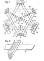
- FIG. 1 shows a top view of a vibration damper.
- This vibration damper is intended, for example, as a version for supporting a machine on a factory floor.
- the lowest structural level is formed by a rigid arm cross. This has three arms 4.
- each arm 4 is rigidly connected to a guide bush 9. At their outermost, ie distal ends, each arm 4 is rigidly connected to a support plate 1.
- the vibration damper is supported on the floor via these three support plates 1.
- the support plates 1 can additionally be provided with an anti-slip device 13.
- these support plates 1 can be "AIR-LOC" (trademark) -Gleit- protective plates. These are known in the specialist world and therefore do not need to be described in detail.
- the support plates 1 can be placed loosely as such on a respective surface. In other versions, however, it is possible to anchor these support plates 1 in the respective floor.
- the support plates 1 are equipped with connectors, here bolts 20. It should be noted that other components can also be present as connectors.
- the connector can also be connected by an inseparable connection, e.g. B. welded point.
- the second layer is formed by three rectilinear leaf springs 71, 72 and 73. These leaf springs 71, 72 and 73, which are arranged in the form of an equilateral triangle, rest at their end regions on a strip 12 of the support plate 1 below. Recesses 29 are formed in the sections of the leaf springs projecting from the strips 12. The screw bolts 20 pass through these recesses 29.
- each leaf spring section is thus clamped on the support plate 1. It is now obvious that the spring tension can be changed by these bolts, so that the preload can be selected within limits.
- the strips 12 run perpendicular to the leaf spring sections 71, 72 and 73, so that maximum utilization of the elastic properties thereof is ensured.
- the third layer of the vibration damper is again formed by an arm cross.
- This has further rigid arms 5.
- the arms 5 are again firmly connected to a guide bush 9, which is separated from the guide bush located underneath.
- FIG. 2 shows the detail A of FIG. 1 in a diagram and on an enlarged scale.
- FIG. 2 shows a part of the leaf spring section 71, for example, and the arm 5 of the upper arm cross lying above it.
- the arm 5 has a wedge-shaped cross-sectional shape with a rounded apex region. This also results in a linear support of the arm 5 on the leaf spring section 71.
- the upper arm cross with the arms 5 is arranged rotated relative to the lower arm cross with the arms 4 by an angle which is half the angular distance between the respective arms.
- the arms 5 thus lie exactly on the center of the leaf spring sections 71, 72, 73 below.
- the fourth layer is in turn formed by leaf spring sections 81, 82, 83 arranged in the equilateral triangle. As can be seen below in FIG. 1, the ends of these leaf spring sections 81, 82, 83 rest on the strips 12 of the support plates 2 running perpendicularly thereto and are connected to them by means of screw bolts 20.
- any number of arm crosses and triangular leaf spring sets can now be layered alternately one above the other.
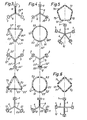
- FIG. 3 Here is a vibration damper designed similar to FIG detailed explanation shown in an exploded state. Various details, such as the rod 10, are not shown. The strips 12 are shown schematically.
- connection points at which a fixed connection is established by means of a screw bolt are indicated with a small circle, and support points, including those present in the strips 12, are indicated with an x.
- the arm cross lying at the bottom in FIG. 3 on the drawing sheet is intended for resting on a machine house floor.
- the arms 4 and the support plates 1 are drawn with the strips 12, which secure the lines of the springs.
- the leaf spring sections 71, 72, 73 are present as a second layer on this arm cross.
- the leaf spring section 72 is connected at point 21 'to the point 21 of the support plate 1 via the screw bolt, and the leaf spring section 71 is connected to the support plate 1 at the point 22', for example.
- the leaf spring section triangle thus lies linearly at its locations 12 'at the strips 12 on the arm cross and is connected to it at the respective outer locations.
- Another arm cross is now arranged above this leaf spring section triangle. This has three arms 5 and the support plates 2. This cross arm now rests on the leaf spring section triangle just described.
- the support points are marked with x.
- the arm 5 which runs vertically on the drawing sheet rests at the point 23 ′′ on the point 23 ′ of the leaf spring section 71.
- the support point 23 'of the leaf spring section 71 has the same distance from the left and right screw connection point 22'.
- the top arm cross now lies on this set of leaf springs. It has three arms 6 and support plates 3.
- the contact point of this arm cross on the leaf spring sections below it is designated, for example, by 26 “" and the contact point on the corresponding leaf spring section 81 below it by 26 “'.
- This top arm cross now carries the machine to be supported directly.
- the support plates 3 can be used for the connection point
- a levelable element is arranged at the uppermost arm cross (and also guided through the centering rod 10. This element can, for example, consist of a ball and a spherical cap.
- a three-point support is provided on the one hand, so that there is an automatic adaptation to the surface and above a hinge connection to the machine frame to be carried, so that the vibration damper can compensate for any position differences between the machine frame and the floor n.
- FIG. 4 Another exemplary embodiment is shown in FIG. 4.
- the lower arm cross is again formed by three rigid arms 4 with the support plates 1.
- the lasts are with. 12 indicated.
- the leaf spring set above is circular and consists of three circular rings cut-shaped leaf spring sections 91, 92 and 93 together.
- the leaf spring section 91 is connected, for example, at 22 ′ via the screw bolt to the point 22 of the underlying support plate, and the leaf spring section 92 is connected, for example, at 21 ′ to the point 21 of the underlying support plate 1.
- the leaf spring sections are supported at the points 12 'on the respective strips 12 below.
- the further arm cross is arranged above the leaf spring set. This is composed of the arms 5 and the support plates 2.
- the support points are marked with x.
- the support point 23 "of the arm 5 lies further out, here under the support plate 2, at which point this cross arm is supported on the leaf spring section 91.
- the position 23 'at which the force acts on the leaf spring 91 does not now of the straight line connecting the two connection points 22 ', the leaf spring section 91 is twisted rather than deflected under load, so the vibration damper does not have to have deflecting leaf springs in every embodiment, as shown here, for example, torsion springs are also possible.
- the further leaf spring set containing the leaf spring sections 91, 92 and 93, rests on the arm cross with the arms 5.
- the leaf spring section 91 is screwed, for example, at 24 ′′ to the point 24 ′′ of the underlying support plate 2, and the leaf spring section 93 is screwed, for example, at 25 ′ ′′ to 25 ′′ of the support plate 2.
- the contact points of the leaf spring sections are indicated with 12 "'and the strips underneath with 12". It should be repeated here that changes in the tension of the leaf springs can be carried out with these screw connections.
- the arm cross with the arms 6 and the support plate 3 is again at the top. Here, the arm 6 is supported via the support plate 3 at the point 26 "" at the point 26 '"of the leaf spring section 91 below.
- FIG. 5 shows, for example, an arm cross containing five arms 4 with the support plates 1.
- the leaf spring sections 71, 72, 73, 74 and 75 lying above describe an equilateral pentagon.
- the screw connection points are also indicated here by circles and the contact points on the leaf spring sections by x.
- the contact points of the leaf spring sections are indicated with 12 'and the strips with 12.
- FIG. 6 shows a four-armed arm cross with the arms 4 and support plates 1 and an overlying leaf spring set in the form of a leaf spring sections 71, 72, 73 and 74 that describe Quarat. These leaf spring sections are screwed at the points shown with the circles to the underlying support plates 1 and the support points on the leaf spring sections are again shown with an x. The contact points of the leaf spring sections are designated 12 'and the strips 12.
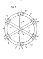
- FIG. 7 shows a further embodiment with annular leaf spring sections.
- the difference between this embodiment of FIG. 7 and the previous embodiments is that the leaf spring sections in one piece are connected, that is, that there is an uninterrupted ring of spring steel.
- the lowest cross arm (compare also with Fig. 1) has three arms 4 and the associated support plates 1. The support plates are provided with the support strips 12.
- rod 10 and guide bush 9 are also indicated schematically.
- On this lowest arm cross lies the circular leaf spring, which is made up of sections 94.95 and 96.
- the reference number 20 designates cap screws (here to be tightened with a screwdriver) by means of which the connection between the leaf spring sections 94, 95 and 96 is formed with the cross arm underneath. In contrast to the previous versions, there is only one screw bolt 20 between two support strips 12.
- the next higher arm cross containing the arms 5 and the support plates 2, now lies on the leaf spring circular ring.
- the strips 12 are again drawn on the support plates 2.
- the reference number 28 denotes the hole with the internal thread for receiving the screw bolt, the one not shown above connects the circular ring with the arm cross 5.2.
Landscapes
- Engineering & Computer Science (AREA)
- General Engineering & Computer Science (AREA)
- Physics & Mathematics (AREA)
- Acoustics & Sound (AREA)
- Aviation & Aerospace Engineering (AREA)
- Mechanical Engineering (AREA)
- Vibration Prevention Devices (AREA)
- Springs (AREA)
Applications Claiming Priority (2)
| Application Number | Priority Date | Filing Date | Title |
|---|---|---|---|
| CH4784/83 | 1983-08-31 | ||
| CH4784/83A CH660406A5 (de) | 1983-08-31 | 1983-08-31 | Mit federn ausgeruesteter mechanischer schwingungsdaempfer. |
Publications (3)
| Publication Number | Publication Date |
|---|---|
| EP0135800A2 true EP0135800A2 (fr) | 1985-04-03 |
| EP0135800A3 EP0135800A3 (en) | 1986-07-09 |
| EP0135800B1 EP0135800B1 (fr) | 1988-12-14 |
Family
ID=4282482
Family Applications (1)
| Application Number | Title | Priority Date | Filing Date |
|---|---|---|---|
| EP84109992A Expired EP0135800B1 (fr) | 1983-08-31 | 1984-08-22 | Amortisseur mécanique de vibrations, pourvu de ressorts |
Country Status (5)
| Country | Link |
|---|---|
| US (1) | US4572471A (fr) |
| EP (1) | EP0135800B1 (fr) |
| CA (1) | CA1213621A (fr) |
| CH (1) | CH660406A5 (fr) |
| DE (1) | DE3475642D1 (fr) |
Cited By (2)
| Publication number | Priority date | Publication date | Assignee | Title |
|---|---|---|---|---|
| US4643385A (en) * | 1984-11-15 | 1987-02-17 | Rca Corporation | Anti-vibration system |
| US5000415A (en) * | 1989-11-08 | 1991-03-19 | Newport Corporation | Active vibration isolation systems |
Families Citing this family (14)
| Publication number | Priority date | Publication date | Assignee | Title |
|---|---|---|---|---|
| FR2623583B2 (fr) * | 1987-06-23 | 1990-04-20 | Hutchinson | Supports elastiques |
| PL157979B1 (pl) * | 1989-02-14 | 1992-07-31 | Sprezyna z dwoma stanami równowagi trwalej PL PL | |
| US5310157A (en) * | 1989-08-16 | 1994-05-10 | Minus K Technology, Inc. | Vibration isolation system |
| US5178357A (en) * | 1989-08-16 | 1993-01-12 | Platus David L | Vibration isolation system |
| US5549270A (en) * | 1989-08-16 | 1996-08-27 | Minus K Technology, Inc. | Vibration isolation system |
| US5139242A (en) * | 1990-11-06 | 1992-08-18 | Yarr George A | Linear suspension device |
| NL1005000C2 (nl) * | 1997-01-14 | 1998-07-15 | Aerpac Special Products B V | Windturbine. |
| US6017013A (en) * | 1997-09-12 | 2000-01-25 | Trw Inc. | Damped instrument kinematic mounts |
| US6378849B1 (en) * | 2001-04-13 | 2002-04-30 | General Electric Company | Methods and apparatus for mounting motors |
| CN108200488B (zh) * | 2016-12-08 | 2022-06-03 | 林球有限公司 | 用于音响器材的防振装置及具有防振装置的音响器材架 |
| CN108018862B (zh) * | 2018-01-11 | 2024-01-30 | 西南交通大学 | 一种适用于被动防护网且便于巡检的柔性基础部件 |
| CN108869626A (zh) * | 2018-09-20 | 2018-11-23 | 上海大学 | 一种金字塔型可调节式隔振平台 |
| US12181016B2 (en) * | 2022-02-15 | 2024-12-31 | Raytheon Company | Superelastic multi axis flexure |
| US12117064B2 (en) * | 2022-02-15 | 2024-10-15 | Raytheon Company | Multi-flexure isolation system utilizing pseudoelastic multi-axis rotational flexures |
Family Cites Families (11)
| Publication number | Priority date | Publication date | Assignee | Title |
|---|---|---|---|---|
| US153594A (en) * | 1874-07-28 | Improvement in vehicle-seats | ||
| DE707778C (de) * | 1940-02-21 | 1941-07-03 | Demag Akt Ges | Niedrigbauender, quersteifer Federkoerper mit Reibdaempfung zur nachgiebigen Lagerung von Maschinen, insbesondere von Walzwerksrollgaengen |
| US2454538A (en) * | 1944-07-17 | 1948-11-23 | Gen Electric | Shockproof support |
| US2580815A (en) * | 1948-12-28 | 1952-01-01 | Us Rubber Co | Vibration isolating support |
| CH348010A (de) * | 1955-11-08 | 1960-07-31 | Allied Res Ass Inc | Vorrichtung zur Dämpfung ungewollter Schwingungen |
| US2901703A (en) * | 1957-02-19 | 1959-08-25 | Gen Electric | Frictionless suspension means for rotary elements |
| US3080160A (en) * | 1960-12-23 | 1963-03-05 | Orner Harry | Spring mechanism |
| US3185428A (en) * | 1963-11-12 | 1965-05-25 | Lord Mfg Co | Mounting system |
| US3417984A (en) * | 1966-11-01 | 1968-12-24 | Ametek Inc | Bearing |
| US3727865A (en) * | 1970-10-09 | 1973-04-17 | Rca Corp | Suspension system |
| US4269400A (en) * | 1979-05-04 | 1981-05-26 | Barry Wright Corporation | Stacked, resilient isolator components |
-
1983
- 1983-08-31 CH CH4784/83A patent/CH660406A5/de not_active IP Right Cessation
-
1984
- 1984-03-23 US US06/592,516 patent/US4572471A/en not_active Expired - Fee Related
- 1984-03-28 CA CA000450750A patent/CA1213621A/fr not_active Expired
- 1984-08-22 EP EP84109992A patent/EP0135800B1/fr not_active Expired
- 1984-08-22 DE DE8484109992T patent/DE3475642D1/de not_active Expired
Cited By (2)
| Publication number | Priority date | Publication date | Assignee | Title |
|---|---|---|---|---|
| US4643385A (en) * | 1984-11-15 | 1987-02-17 | Rca Corporation | Anti-vibration system |
| US5000415A (en) * | 1989-11-08 | 1991-03-19 | Newport Corporation | Active vibration isolation systems |
Also Published As
| Publication number | Publication date |
|---|---|
| CA1213621A (fr) | 1986-11-04 |
| DE3475642D1 (en) | 1989-01-19 |
| EP0135800B1 (fr) | 1988-12-14 |
| EP0135800A3 (en) | 1986-07-09 |
| US4572471A (en) | 1986-02-25 |
| CH660406A5 (de) | 1987-04-15 |
Similar Documents
| Publication | Publication Date | Title |
|---|---|---|
| EP0135800B1 (fr) | Amortisseur mécanique de vibrations, pourvu de ressorts | |
| DE3590456C2 (de) | Klemmvorrichtung | |
| DE1207714B (de) | Biegsames Zwischenstueck zur UEbertragung von Kraeften in angenaehert gerader Richtung | |
| DE296974T1 (de) | Elastische lager. | |
| DE3242730A1 (de) | Abstandshalter fuer leiterplatten und zusammengebaute leiterplattenanordnung | |
| DE2406106C3 (de) | Stützisolatoranordnung | |
| DE3830445A1 (de) | Klammerhalterung zur befestigung einer trommel an einer haltestange | |
| CH681915A5 (fr) | ||
| DE202013101707U1 (de) | Aktorgehäuse | |
| DE1930612U (de) | Elastisches lagerungselement. | |
| DE1775472C3 (de) | Tragvorrichtung für einen Gegenstand, die die Übertragung von Stößen und Schwingungen auf diesen Gegenstand schwächt | |
| DE69701947T2 (de) | Aufhängung von Auspuffanlagen | |
| DE3821436A1 (de) | Motoraufhaengung | |
| DE2633612C3 (de) | Elastischer Puffer | |
| DE102015106210B4 (de) | Schwingungsisolationseinheit | |
| DE2309950C3 (de) | Schwingungsdämpfende Maschinenunterlage | |
| DE3322726C2 (fr) | ||
| EP0197385B1 (fr) | Dispositif d'atténuation sonore | |
| DE69201124T2 (de) | Elastische Aufhängungsvorrichtung mit verschiedenen Steifheiten zur Lagerung eines Geräts. | |
| DE3501415A1 (de) | Kupplungsvorrichtung mit flexiblen lamellen | |
| DE2263985C3 (de) | Fuß für Geräte und Maschinen | |
| DE3014593C2 (de) | Dämpfungsarmes Lager | |
| DE19938739C2 (de) | Schalldämmeinrichtung in Form eines Punktlagerelements | |
| DE2714528A1 (de) | Federkoerper mit dehnstreifen fuer kraftmessungen | |
| DE202022101618U1 (de) | Tragendes Verbindungsstück für vorgefertigte Gebäude und vorgefertiges Gebäude |
Legal Events
| Date | Code | Title | Description |
|---|---|---|---|
| PUAI | Public reference made under article 153(3) epc to a published international application that has entered the european phase |
Free format text: ORIGINAL CODE: 0009012 |
|
| AK | Designated contracting states |
Designated state(s): AT BE DE FR GB IT LU NL |
|
| PUAL | Search report despatched |
Free format text: ORIGINAL CODE: 0009013 |
|
| AK | Designated contracting states |
Kind code of ref document: A3 Designated state(s): AT BE DE FR GB IT LU NL |
|
| 17P | Request for examination filed |
Effective date: 19860910 |
|
| 17Q | First examination report despatched |
Effective date: 19880219 |
|
| GRAA | (expected) grant |
Free format text: ORIGINAL CODE: 0009210 |
|
| AK | Designated contracting states |
Kind code of ref document: B1 Designated state(s): DE |
|
| REF | Corresponds to: |
Ref document number: 3475642 Country of ref document: DE Date of ref document: 19890119 |
|
| PGFP | Annual fee paid to national office [announced via postgrant information from national office to epo] |
Ref country code: DE Payment date: 19890901 Year of fee payment: 6 |
|
| PLBE | No opposition filed within time limit |
Free format text: ORIGINAL CODE: 0009261 |
|
| STAA | Information on the status of an ep patent application or granted ep patent |
Free format text: STATUS: NO OPPOSITION FILED WITHIN TIME LIMIT |
|
| 26N | No opposition filed | ||
| PG25 | Lapsed in a contracting state [announced via postgrant information from national office to epo] |
Ref country code: DE Effective date: 19910501 |