EP0135873A2 - Injecteur de combustible pour moteurs à combustion interne - Google Patents
Injecteur de combustible pour moteurs à combustion interne Download PDFInfo
- Publication number
- EP0135873A2 EP0135873A2 EP84110675A EP84110675A EP0135873A2 EP 0135873 A2 EP0135873 A2 EP 0135873A2 EP 84110675 A EP84110675 A EP 84110675A EP 84110675 A EP84110675 A EP 84110675A EP 0135873 A2 EP0135873 A2 EP 0135873A2
- Authority
- EP
- European Patent Office
- Prior art keywords
- injection nozzle
- sensor
- closing spring
- resistance
- injection
- Prior art date
- Legal status (The legal status is an assumption and is not a legal conclusion. Google has not performed a legal analysis and makes no representation as to the accuracy of the status listed.)
- Ceased
Links
- 239000000446 fuel Substances 0.000 title claims abstract description 6
- 238000002485 combustion reaction Methods 0.000 title claims abstract description 4
- 238000002347 injection Methods 0.000 claims abstract description 13
- 239000007924 injection Substances 0.000 claims abstract description 13
- 239000004020 conductor Substances 0.000 claims description 7
- 239000000919 ceramic Substances 0.000 claims description 3
- 239000011521 glass Substances 0.000 claims description 3
- 239000004033 plastic Substances 0.000 claims description 3
- 150000001875 compounds Chemical class 0.000 claims description 2
- 239000012777 electrically insulating material Substances 0.000 claims description 2
- 239000010408 film Substances 0.000 description 6
- 230000001419 dependent effect Effects 0.000 description 3
- 238000011156 evaluation Methods 0.000 description 3
- YJLIKUSWRSEPSM-WGQQHEPDSA-N (2r,3r,4s,5r)-2-[6-amino-8-[(4-phenylphenyl)methylamino]purin-9-yl]-5-(hydroxymethyl)oxolane-3,4-diol Chemical compound C=1C=C(C=2C=CC=CC=2)C=CC=1CNC1=NC=2C(N)=NC=NC=2N1[C@@H]1O[C@H](CO)[C@@H](O)[C@H]1O YJLIKUSWRSEPSM-WGQQHEPDSA-N 0.000 description 1
- 238000000418 atomic force spectrum Methods 0.000 description 1
- 238000011161 development Methods 0.000 description 1
- 230000018109 developmental process Effects 0.000 description 1
- 238000005538 encapsulation Methods 0.000 description 1
- 238000009413 insulation Methods 0.000 description 1
- 238000005259 measurement Methods 0.000 description 1
- 239000010409 thin film Substances 0.000 description 1
- 238000011144 upstream manufacturing Methods 0.000 description 1
Images
Classifications
-
- F—MECHANICAL ENGINEERING; LIGHTING; HEATING; WEAPONS; BLASTING
- F02—COMBUSTION ENGINES; HOT-GAS OR COMBUSTION-PRODUCT ENGINE PLANTS
- F02M—SUPPLYING COMBUSTION ENGINES IN GENERAL WITH COMBUSTIBLE MIXTURES OR CONSTITUENTS THEREOF
- F02M65/00—Testing fuel-injection apparatus, e.g. testing injection timing ; Cleaning of fuel-injection apparatus
- F02M65/005—Measuring or detecting injection-valve lift, e.g. to determine injection timing
Definitions
- the invention relates to a fuel injection nozzle according to the preamble of the main claim.
- the pressure-dependent electrical component of the transmitter is a piezo plate, which is clamped between disc-shaped electrodes and dimensionally stable contact or support plates.
- the use of a piezo plate as a pressure-dependent electrical component has the disadvantage that, due to the rapidly flowing charges, not the actual spring force but a differentiated force signal is detected, so that an evaluation over the entire speed range, in particular because of the strongly oscillating closing spring during the closing stroke of the valve needle is difficult.
- the arrangement of piezo plate electrodes must be insulated with high resistance to prevent the charges from flowing away in an uncontrolled manner. However, this can only be achieved through complex encapsulation and high-quality insulation measures.
- the arrangement according to the invention with the characterizing features of the main claim has the advantage that the connecting conductors can be soldered to the resistance body, resulting in a reliable and vibration-free contact.
- a change in resistance is available as a measurement signal, which can be easily converted into a voltage signal in a bridge circuit.
- the transmitter measures statically, i.e. regardless of the rate of change of the spring force, so that the actual force is detected and the actual force curve can be recorded.
- the pressure-dependent component of the transmitter which is designed as a low-resistance resistor body, is also significantly less sensitive to interference and easier to isolate than a piezo element.
- the electrical component of the transducer is a thick film resistor is particularly advantageous. This has a much higher signal yield than e.g. a thin film resistor and can also be manufactured more easily than this.
- a compact design results if the electrical resistance body is placed on a preferably flat support made of electrically insulating material, such as ceramic, glass,
- Plastic arranged and cast together with this between two dimensionally stable disks by means of a hard, but permanently elastic filling compound.
- the carrier can be made very thin, so that the entire transducer is not thicker than the disks previously used to adjust the opening pressure of the injection nozzle.
- Simple contacting is possible if the sensor is designed as a ring disk body and its electrical resistance body is connected to at least one connecting conductor track protruding into the central opening of the ring disk body.
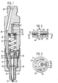
- FIG. 1 shows a longitudinal section through an injection nozzle for diesel engines
- FIG. 2 shows an enlarged section through the sensor of the injection nozzle according to FIG. 1
- FIG. 3 shows a section along the line III-III in FIG. 2.
- the injection nozzle has a nozzle body 10 which, together with an intermediate disk 12, is clamped to a nozzle holder 16 by a union nut 14 ′.
- a valve seat 20 upstream of an ejection opening 18 is formed in the nozzle body 10 and a valve needle 22 is displaced bar mounted, which is pressed by a closing spring 24 via a pressure piece 26 against the valve seat 20.
- the valve needle 22 is surrounded in the region of a pressure shoulder 28 by a pressure chamber 30 which is connected via channels 32, 34 and 36 in the nozzle body 10, in the intermediate disk 12 and the nozzle holder 16 to a connection piece 38 formed on the latter for a fuel supply line.
- the closing spring 24 is supported on a shoulder 42 of the nozzle holder 16 by means of an annular disk-shaped measuring transducer, provided as a whole with the reference number 40.
- the transducer 40 has a thick-film resistor 44 in the form of a ring cut at one point, which is applied to a likewise ring-shaped carrier body 46 made of ceramic, glass or plastic.
- the thick-film resistor 44 is cast in together with the carrier body 46 by means of a hard but permanently elastic filling compound 48 between two dimensionally stable ring disks 50, 52.
- To contact the thick-film resistor 44 its ends 54, 56 are each provided with a connecting conductor 58, 60, which protrude into the central opening 62 of the transmitter 40.
- the carrier body 46 is also provided with a projection 64 projecting radially inwards.
- the carrier body 46 is also provided with a projection 64 projecting radially inwards.
- the carrier body 46 is also provided with a projection 64 projecting radially inwards.
- On the Ansehlußleiterbahnen58, 60 are further conductors. 66, 68 soldered, which are led to the outside through a leak oil hole 70 in the nozzle holder 16 and are provided there with means for connecting an evaluation circuit.
- the washer 50 lies against the shoulder 42 of the nozzle holder 16 and the washer 52 supports the closing spring 24, so that the thick-film resistor 44 is constantly loaded by the closing pressure of the closing spring 24.
- the closing force changes occurring during operation of the internal combustion engine due to the working of the closing spring 24 are thus converted by the thick-film resistor 44 into corresponding resistance changes both in terms of their size and in terms of the time of their occurrence, and processed further in the connected evaluation circuit.
- the changes in resistance are independent of the rate of change of the closing force, so that the actual magnitude of the closing force is detected and processed at all times.
Landscapes
- Engineering & Computer Science (AREA)
- Chemical & Material Sciences (AREA)
- Combustion & Propulsion (AREA)
- Mechanical Engineering (AREA)
- General Engineering & Computer Science (AREA)
- Fuel-Injection Apparatus (AREA)
Applications Claiming Priority (2)
| Application Number | Priority Date | Filing Date | Title |
|---|---|---|---|
| DE19833333287 DE3333287A1 (de) | 1983-09-15 | 1983-09-15 | Kraftstoff-einspritzduese fuer brennkraftmaschinen |
| DE3333287 | 1983-09-15 |
Publications (2)
| Publication Number | Publication Date |
|---|---|
| EP0135873A2 true EP0135873A2 (fr) | 1985-04-03 |
| EP0135873A3 EP0135873A3 (fr) | 1987-03-04 |
Family
ID=6209125
Family Applications (1)
| Application Number | Title | Priority Date | Filing Date |
|---|---|---|---|
| EP84110675A Ceased EP0135873A3 (fr) | 1983-09-15 | 1984-09-07 | Injecteur de combustible pour moteurs à combustion interne |
Country Status (3)
| Country | Link |
|---|---|
| EP (1) | EP0135873A3 (fr) |
| JP (1) | JPS6065273A (fr) |
| DE (1) | DE3333287A1 (fr) |
Cited By (1)
| Publication number | Priority date | Publication date | Assignee | Title |
|---|---|---|---|---|
| DE3830510C1 (en) * | 1988-09-08 | 1989-12-14 | Daimler-Benz Aktiengesellschaft, 7000 Stuttgart, De | Device for determining the rate of injection in internal combustion engines or the like |
Family Cites Families (2)
| Publication number | Priority date | Publication date | Assignee | Title |
|---|---|---|---|---|
| US3596507A (en) * | 1968-08-20 | 1971-08-03 | Toyoda Chuo Kenkyusho Kk | Apparatus for detecting the injection timing of an internal combustion engine |
| US4311980A (en) * | 1978-10-12 | 1982-01-19 | Fabrica Italiana Magneti Marelli, S.P.A. | Device for pressure measurement using a resistor strain gauge |
-
1983
- 1983-09-15 DE DE19833333287 patent/DE3333287A1/de not_active Withdrawn
-
1984
- 1984-07-30 JP JP15775384A patent/JPS6065273A/ja active Pending
- 1984-09-07 EP EP84110675A patent/EP0135873A3/fr not_active Ceased
Cited By (1)
| Publication number | Priority date | Publication date | Assignee | Title |
|---|---|---|---|---|
| DE3830510C1 (en) * | 1988-09-08 | 1989-12-14 | Daimler-Benz Aktiengesellschaft, 7000 Stuttgart, De | Device for determining the rate of injection in internal combustion engines or the like |
Also Published As
| Publication number | Publication date |
|---|---|
| JPS6065273A (ja) | 1985-04-15 |
| DE3333287A1 (de) | 1985-04-18 |
| EP0135873A3 (fr) | 1987-03-04 |
Similar Documents
| Publication | Publication Date | Title |
|---|---|---|
| EP0148321B1 (fr) | Capteur de pression à résistance | |
| DE19827287A1 (de) | Brennstoffeinspritzventil-Drucksensor- Kombination | |
| EP0594796B1 (fr) | Detecteur de cognement | |
| EP0184666B1 (fr) | Détecteur de la détonation | |
| DE2739628A1 (de) | Steuerventil | |
| DE2920669C2 (fr) | ||
| EP0140066A1 (fr) | Dispositif pour la détection de forces, tensions resp. des accélérations de machines, appareils ou similaires | |
| DE3423711C2 (de) | Meßwertaufnehmer zur Messung heißer Medien, sowie Verfahren zu seiner Montage | |
| EP0480132A2 (fr) | Interrupteur à passage de fluide ou à pression pour une conduite de fluide | |
| DE2809455A1 (de) | Einrichtung zur luftmengenmessung | |
| EP0386446A1 (fr) | Conduit de distribution de carburant pour systèmes d'injection de moteurs à combustion interne | |
| EP0135873A2 (fr) | Injecteur de combustible pour moteurs à combustion interne | |
| EP0204722B1 (fr) | Dispositif d'injection de carburant dans la chambre de combustion d'un moteur a combustion interne | |
| DE1049635B (de) | Vorrichtung zum elektrischen Messen des Hubes von Düsennadeln für Brennstoffeinspritzdüsen von Brennkraftmaschinen | |
| DE19524147A1 (de) | Sensor mit Druckhülse | |
| DE1963988C3 (de) | Strömungstaster | |
| DE69513604T2 (de) | Kraftstoffeinspritzvorrichtung | |
| EP0042915B1 (fr) | Soupape d'injecteur de combustible pour moteur à combustion | |
| DE2949705A1 (de) | Kraftstoffeinspritzduese fuer brennkraftmaschinen | |
| DE3019551A1 (de) | Piezoelektrischer beschleunigungsaufnehmer | |
| DE8436486U1 (de) | Klopfsensor | |
| DE10009169A1 (de) | Schwingungsaufnehmer mit einer Druckhülse | |
| DE19960325A1 (de) | Schwingungsaufnehmer mit einer Druckhülse | |
| DE3610351A1 (de) | Drucksensor | |
| EP0349529A1 (fr) | Detecteur de pression. |
Legal Events
| Date | Code | Title | Description |
|---|---|---|---|
| PUAI | Public reference made under article 153(3) epc to a published international application that has entered the european phase |
Free format text: ORIGINAL CODE: 0009012 |
|
| 17P | Request for examination filed |
Effective date: 19840907 |
|
| AK | Designated contracting states |
Designated state(s): DE FR GB IT |
|
| PUAL | Search report despatched |
Free format text: ORIGINAL CODE: 0009013 |
|
| AK | Designated contracting states |
Kind code of ref document: A3 Designated state(s): DE FR GB IT |
|
| 17Q | First examination report despatched |
Effective date: 19880217 |
|
| STAA | Information on the status of an ep patent application or granted ep patent |
Free format text: STATUS: THE APPLICATION HAS BEEN REFUSED |
|
| 18R | Application refused |
Effective date: 19890103 |
|
| RIN1 | Information on inventor provided before grant (corrected) |
Inventor name: DOBLER, KLAUS, DR. DIPL.-ING. |