EP0136048B1 - Method and apparatus for applying a coating material to a pipe - Google Patents
Method and apparatus for applying a coating material to a pipe Download PDFInfo
- Publication number
- EP0136048B1 EP0136048B1 EP84305645A EP84305645A EP0136048B1 EP 0136048 B1 EP0136048 B1 EP 0136048B1 EP 84305645 A EP84305645 A EP 84305645A EP 84305645 A EP84305645 A EP 84305645A EP 0136048 B1 EP0136048 B1 EP 0136048B1
- Authority
- EP
- European Patent Office
- Prior art keywords
- pipe
- coating material
- notching
- wrapping
- belt
- Prior art date
- Legal status (The legal status is an assumption and is not a legal conclusion. Google has not performed a legal analysis and makes no representation as to the accuracy of the status listed.)
- Expired
Links
Images

Classifications
-
- B—PERFORMING OPERATIONS; TRANSPORTING
- B28—WORKING CEMENT, CLAY, OR STONE
- B28B—SHAPING CLAY OR OTHER CERAMIC COMPOSITIONS; SHAPING SLAG; SHAPING MIXTURES CONTAINING CEMENTITIOUS MATERIAL, e.g. PLASTER
- B28B21/00—Methods or machines specially adapted for the production of tubular articles
- B28B21/42—Methods or machines specially adapted for the production of tubular articles by shaping on or against mandrels or like moulding surfaces
- B28B21/48—Methods or machines specially adapted for the production of tubular articles by shaping on or against mandrels or like moulding surfaces by wrapping, e.g. winding
-
- B—PERFORMING OPERATIONS; TRANSPORTING
- B65—CONVEYING; PACKING; STORING; HANDLING THIN OR FILAMENTARY MATERIAL
- B65H—HANDLING THIN OR FILAMENTARY MATERIAL, e.g. SHEETS, WEBS, CABLES
- B65H81/00—Methods, apparatus, or devices for covering or wrapping cores by winding webs, tapes, or filamentary material, not otherwise provided for
- B65H81/06—Covering or wrapping elongated cores
- B65H81/08—Covering or wrapping elongated cores by feeding material obliquely to the axis of the core
-
- F—MECHANICAL ENGINEERING; LIGHTING; HEATING; WEAPONS; BLASTING
- F16—ENGINEERING ELEMENTS AND UNITS; GENERAL MEASURES FOR PRODUCING AND MAINTAINING EFFECTIVE FUNCTIONING OF MACHINES OR INSTALLATIONS; THERMAL INSULATION IN GENERAL
- F16L—PIPES; JOINTS OR FITTINGS FOR PIPES; SUPPORTS FOR PIPES, CABLES OR PROTECTIVE TUBING; MEANS FOR THERMAL INSULATION IN GENERAL
- F16L58/00—Protection of pipes or pipe fittings against corrosion or incrustation
- F16L58/02—Protection of pipes or pipe fittings against corrosion or incrustation by means of internal or external coatings
- F16L58/04—Coatings characterised by the materials used
- F16L58/06—Coatings characterised by the materials used by cement, concrete, or the like
-
- F—MECHANICAL ENGINEERING; LIGHTING; HEATING; WEAPONS; BLASTING
- F16—ENGINEERING ELEMENTS AND UNITS; GENERAL MEASURES FOR PRODUCING AND MAINTAINING EFFECTIVE FUNCTIONING OF MACHINES OR INSTALLATIONS; THERMAL INSULATION IN GENERAL
- F16L—PIPES; JOINTS OR FITTINGS FOR PIPES; SUPPORTS FOR PIPES, CABLES OR PROTECTIVE TUBING; MEANS FOR THERMAL INSULATION IN GENERAL
- F16L58/00—Protection of pipes or pipe fittings against corrosion or incrustation
- F16L58/02—Protection of pipes or pipe fittings against corrosion or incrustation by means of internal or external coatings
- F16L58/16—Protection of pipes or pipe fittings against corrosion or incrustation by means of internal or external coatings the coating being in the form of a bandage
Definitions
- the present invention relates to an apparatus for applying a coating material to a pipe wherein the coating material isfirstapplied in an even layerto a carrier tape which is then wrapped spirally about the pipe.
- the coating material may be a cementatious material such as concrete or it may be a thermoplastic material or other suitable coating material.
- the apparatus is provided with means foreffecting a continuous interlocking overlapping of the coating strip as it is applied to the pipe. This type of overlapping ensures that the coating material is applied evenly and concentrically about the pipe, and when one or more strips of reinforcing mesh are provided within the coating material layer, this continuous overlap provides uniform mesh reinforcement along the full length of the coated pipe with a positive overlap of the mesh at the wrapping seam.
- Concrete coated pipe is commonly used in underwater applications for oil and gas transmission, and such coating for the most part is used to give the pipe negative buoyancy.
- the concrete coating can also serve to protect the pipe from other external hazards and for this reason is sometimes used to give physical protection to a span of exposed pipe.
- the coating applied to the pipe be continuous and of an even thickness so that the desired weighting of the pipe is obtained and so that the coating once applied will be resistant to deterioration.
- Most prior wrapping devices make no provision for the positive overlap of the concrete layer as it is being applied to the pipe.
- the concrete used for coating a pipe cannot be too plastic or the coating will be unacceptably susceptible to handling damage prior to setting.
- prior devices do not provide forthe accurate positioning of a reinforcing mesh so that a concentric mesh reinforcement is achieved in the concrete layer wrapped about the pipe. This is especially critical when wrapping pipe of small diameter, i.e, in the 4 to 6 inch (10 to 15 cm) range.
- specifications often call for the use of two mesh layers for added reinforcement.
- the present apparatus is especially well suited to incorporate two mesh layers positioned in the concrete wrapping so that such reinforcement may be provided either concentrically coplanar or non-coplanar about the pipe with a positive overlap of both mesh layers at the wrapping seam.
- previous devices were not capable of applying a coating having two reinforcing mesh layers wherein each mesh layer formed a positive overlap at the seam.
- U.S. Patent 2,037,043 discloses a cement coating on a tape wrapped about a pipe so that the edges overlap.
- Guide plate 16 and stepped portion 17 provide a strip of outer tape which does not have a cement coating, and this uncoated tape portion provides an overlap at the seam.
- U.S. Patent 4,006,049 discloses a method in which a coating material is compressively wrapped about a pipe by an apparatus which may be modified to have the wrapping strip overlap at the wrapping seam.
- Prior devices have relied on compression of the coating during the wrapping process to compact the concrete and to fill in any gaps along the seam.
- this compression wrapping technique is coupled with a vibrator, but generally the prior devices rely on the plasticity of the concrete being used to achieve the desired quality of the coating at the joint of the application ofthe wrapping to the pipes.
- the present device utilises a fairly dry concrete mixture which is wrapped about the pipe and subsequently subjected to a compacting operation by means of a vibrating shoe. This procedure is superior to that previously employed because the drier concrete mixture is not as susceptible to damage prior to setting, and the reinforcing mesh is much less vulnerable to displacement from the desired position within the concrete layer.
- the present invention provides an apparatus for wrapping pipe having:
- the present invention also provides a method as disclosed in claim 10.
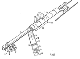
- a pipe 10 is conveyed and rotated by conventional conveyor means 11, and the pipe 10 is wrapped spirally with a strip 12 of coating material advanced at an angle thereto also in a conventional fashion.
- the strip 12 comprises a carrier tape 13 upon which is applied a layer of coating material 14 preferably having at least one continuous strip of reinforcing mesh 16 embedded therein.
- the coating material 14 is preferably concrete having a low water content so that it will set rapidly and have low plasticity.
- the wrapping strip 12 can be wrapped uniformly about the pipe 10 in a fashion superior to that previously available by virtue of the notches 19 which are made in the coating material 14 along both edges of the strip 12 so that upon wrapping, the strip 12 overlaps with itself at a spiral seam 20 to ensure evenness of coating and continuity of the reinforcing mesh 16.
- the carrier tape 13 preferably has an uncoated edge 21 which forms an exterior overlap at the spiral seam 20.
- the wrapped pipe 22 is contacted with a shoe 25 having a vibrator 26 which operates to smooth, compact and increase the density of the coating material 14 and to cause an intermingling of the coating material 14 at the seam 20.
- the shoe 25 is preferably made of steel and is curved to conform to the outside diameter of the wrapped pipe 22.
- each shoe 25 may be used over a range of diameters so a large number of shoes 25 are not required in order to cover a wide range of wrapping applications.
- it is especially important to achieve the maximum density possible for the coating material 14 so that the required negative buoyancy can be obtained without excessively increasing the pipe diameter.
- a low coefficient of friction is maintained between the contacting surfaces of the wrapped pipe 22 and the shoe 25 by virtue of the vibration of the shoe 25 and optionally by applying a light spray of water to the exterior of the wrapped pipe 22.
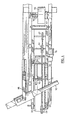
- the preferred pipe wrapping apparatus of the invention is shown in Figures 2 and 4.
- the apparatus comprises a frame 30 which is pivotable about a pin 31 so that the angle of application of the coating strip to the pipe 10 can be adjusted as conditions require.
- a main endless belt 32 wrapped about a drive pulley 33 at the forward end of the apparatus and a rear pulley 34 which is freely rotatable and is mounted in an adjustable bracket 36 so that the belt 32 can be properly tensioned.
- a third freely rotatably pulley 37 is located between the drive pulley 33 and the rear pulley 34 for the purpose of supporting the belt 32 in the area beneath a roller 70 used to form the coating layer 14 just prior to wrapping.
- a main belt 32 having a 12 inch (30cm) width is sufficient.
- a slider bed 40 is attached to the frame 30 between the pulleys 33 and 34.
- This slider bed 40 comprises a chamber having a plurality of holes in its top surface through which is forced air to provide a slight air cushion for the belt 32.
- At least one endless notching belt 45 is positioned near one edge of the main belt 32 and is supported thereon.
- the notching belt 45 is guided by means of a forward pulley 46 positioned above the drive pulley 33 and by means of a rearward pulley 47 which is adjustable in the bracket 36 for tensioning of the belt 45 .
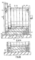
- Provision is also made for a second notching belt 50 which may be positioned just inside of the notching belt 45, i.e. toward the center of the main belt 32, or under the belt 45 to create a stepped notch in the coating material as shown in Fig. 3A.
- This second notching belt 50 when used in conjunction with the notching belt 45 is guided by the forward pulley 46 and by a rearward pulley 51 which is also adjustable in the bracket 36.
- a first reel 55 for carrying a spool of carrier tape 56 which is fed over a guide roller 57 onto the main belt 32.
- the reel 55 is adjustable laterally (see Fig. 4) so that the tape 56 can be lined up properly adjacent the innermost notching belt either 45 or 50.
- additional reels (not shown) are provided for one or two spools of reinforcing mesh 16 which are initially positioned over the carrier tape 13 by means of guide rollers 59.
- the hopper 65 may have adjustable sides 66 to allow for varying widths for the coating strip 12.
- the front wall 67 of the hopper 65 has an aperture 68 through which the coated strip 12 passes on its way to the pipe 10.
- a notch forming roller 70 Positioned in the aperture 68 of the hopper 65 is a notch forming roller 70.
- the roller 70 is located directly over and rotates in a direction opposite to the pulley 37.
- the roller 70 is mounted in adjustable bearings 71 to accommodate various thicknesses for the coating material 14.
- the hopper 65 is provided with an adjustable gate 73 (not shown) located above the roller 70 to close off that upper portion of the aperture 68 not occupied by the roller 70.
- the roller 70 is driven by a motor 75 mounted on the frame 30.
- the roller 70 is constructed from a plurality of disks 76 which are joined together by bolts 77.
- the roller 70 is mounted on an axle 78 which is supported by the adjustable bearings 71.
- At the end of the roller 70 opposite from the notching belts 45 and 50 (Fig. 3A) are mounted two notching disks 80 and 81 which operate to notch the coating material 14 in a complementary fashion to the notching accomplished by the belts 45 and 50 so that the coating strip 12 interlocks at the seam 20 upon wrapping of the pipe 10 (Fig. 1).
- a mesh positioning disk 85 may be added to the roller 70 to ensure the accurate placement of the reinforcing mesh 16 in the finished coating strip 12.
- the disk 85 is thin so as to minimize the disturbance to the coating material 14, but it is also rigid so that it can act in conjunction with the notching belt 45 to position the mesh 16 at the desired location in the coating material 14.
- the positioning disk 85 is operational only with respect to the upper layer of mesh 16 in a dual mesh system as shown in Figure 3A, or when only one layer of mesh 16 is used.
- the mesh 16 may be positioned horizontally in the coating material 14 (Fig. 3A) to give concentric reinforcement of the coating about the pipe 10, or the mesh 16 can be positioned on an angle (Fig. 3B) in the coating material 14 to give a non-coplanar reinforcement when wrapped about the pipe 10.
- the operation of the apparatus for forming the coating strip 12 and wrapping the pipe 10 proceeds as follows.
- the carrier tape 13, which is preferably a plastic material, is fed from the spool 56 onto the main belt 32 with one edge of the tape 13 abutting the inner notching belt either 45 or 50 also riding on the main belt 32 (see Figs. 3A and 3B).
- the tape 13 is fed through the hopper 65 with the edge 21 away from the notching belts 45 and 50 extending beyond the hopper wall 66 so that a margin of uncoated tape 90 (Figs. 3A and 3B) is provided for overlapping the seam 20 of the wrapped pipe 22.
- the desired number of mesh strips 16 are fed from reels (not shown) through the guide rollers 59 into the hopper 65 where they are positioned within the layer of coating material 14 deposited from the hopper 65 onto the tape 13 by means of the initial guide rollers 59, the notching belts 45 and 50 and the roller70 optionally equipped with the positioning disk 85.
- the notching belts 45 and 50 form notches in the coating material corresponding to their heights and widths, and the roller 70 makes corresponding notches in the coating material 14 diagonally opposite from the notches formed by the belts 45 and 50.
- the formed coating strip 12 proceeds from the roller 70 between the conveyor side guards 92 to the pipe 10 where it is spirally wrapped about it so that the notches formed as aforesaid overlap and interlock with the tape margin 90 overlapping the formed seam 20.
- the notching belts 45 and 50 support the coating material 14 during approxi- matelythefirst quarter turn of wrapping so thatthe integrity of the notches formed by the belts 45 and 50 is assured (see Fig. 2). This is achieved by the arrangement of the pu Iley 46 located at the front of the apparatus to guide the belts 45 and 50 during the wrapping portion of the operation.
- the wrapped pipe 22 is immediately subjected to a finishing operation wherein the vibrating shoe 25 causes the coating material 14 to flow so as to fill in the seam 20 and other cracks and voids which may have developed up to that stage.
- the shoe 25 is preferably mounted pivotally on the frame 30 by an arm 95 and may be positioned on the wrapped pipe 22 by a cylinder 96.
Landscapes
- Engineering & Computer Science (AREA)
- General Engineering & Computer Science (AREA)
- Mechanical Engineering (AREA)
- Manufacturing & Machinery (AREA)
- Chemical & Material Sciences (AREA)
- Ceramic Engineering (AREA)
- Lining Or Joining Of Plastics Or The Like (AREA)
- Centrifugal Separators (AREA)
- Registering Or Overturning Sheets (AREA)
- Coating Apparatus (AREA)
- Application Of Or Painting With Fluid Materials (AREA)
Applications Claiming Priority (2)
| Application Number | Priority Date | Filing Date | Title |
|---|---|---|---|
| CA435502 | 1983-08-26 | ||
| CA000435502A CA1216505A (en) | 1983-08-26 | 1983-08-26 | Method and apparatus for applying a coating material to a pipe |
Publications (2)
| Publication Number | Publication Date |
|---|---|
| EP0136048A1 EP0136048A1 (en) | 1985-04-03 |
| EP0136048B1 true EP0136048B1 (en) | 1989-05-31 |
Family
ID=4125957
Family Applications (1)
| Application Number | Title | Priority Date | Filing Date |
|---|---|---|---|
| EP84305645A Expired EP0136048B1 (en) | 1983-08-26 | 1984-08-20 | Method and apparatus for applying a coating material to a pipe |
Country Status (9)
| Country | Link |
|---|---|
| EP (1) | EP0136048B1 (da) |
| AU (1) | AU548455B2 (da) |
| CA (1) | CA1216505A (da) |
| DE (1) | DE3478489D1 (da) |
| DK (1) | DK406884A (da) |
| EG (1) | EG16432A (da) |
| MX (1) | MX166398B (da) |
| NO (1) | NO159311C (da) |
| NZ (1) | NZ209314A (da) |
Cited By (3)
| Publication number | Priority date | Publication date | Assignee | Title |
|---|---|---|---|---|
| WO2009157748A1 (en) * | 2008-06-24 | 2009-12-30 | Merit Technologies Sdn Bhd | Method for repairing and/or strengthening of pipes |
| WO2010048658A1 (en) * | 2008-10-29 | 2010-05-06 | Ashley Iles | Spiral wrap applicator |
| US7971610B2 (en) | 2004-07-02 | 2011-07-05 | Iti Scotland Limited | Tubular bodies and methods of forming same |
Families Citing this family (15)
| Publication number | Priority date | Publication date | Assignee | Title |
|---|---|---|---|---|
| US4759390A (en) * | 1986-11-25 | 1988-07-26 | Shaw Industries Ltd. | Coated metal pipe having bending capability |
| FR2693134B1 (fr) * | 1992-07-02 | 1994-10-14 | Plastic Omnium Cie | Procédé pour réaliser un tube métallique gainé extérieurement. |
| GB2280889B (en) * | 1993-08-12 | 1998-04-01 | Royal Ordnance Plc | Hollow elongated or tubular bodies and their manufacture |
| US5837083A (en) * | 1993-08-12 | 1998-11-17 | Booth; John Peter | Method of forming a rigid tubular body |
| GB2303896B (en) * | 1994-06-04 | 1997-09-03 | Thomas Christopher Arnott | Improvements relating to pipeline insulation and anticorrosion protection |
| GB9411218D0 (en) * | 1994-06-04 | 1994-07-27 | Arnott Thomas C | Improvements relating to pipeline insulation and anticorrosion protection |
| RU2157946C1 (ru) * | 1999-04-30 | 2000-10-20 | Закрытое акционерное общество "Научно-производственное предприятие "Комплекс" | Устройство для нанесения изоляционного ленточного покрытия на трубопровод |
| RU2153620C1 (ru) * | 1999-04-30 | 2000-07-27 | Закрытое акционерное общество "Научно-производственное предприятие "Комплекс" | Блок исходных материалов для изоляционного покрытия трубопровода и способ нанесения покрытия |
| RU2245483C2 (ru) * | 2002-10-29 | 2005-01-27 | Общество с ограниченной ответственностью производственно-коммерческая фирма "Промтех-НН" | Машина для нанесения изолирующей ленты (варианты) |
| RU2315225C2 (ru) * | 2005-03-15 | 2008-01-20 | Открытое акционерное общество "Газпром" (ОАО "Газпром") | Способ нанесения на трубопровод изолирующей ленты |
| RU2325585C1 (ru) * | 2007-02-21 | 2008-05-27 | Открытое акционерное общество "Газпром" | Способ нанесения изоляционного покрытия на трубопровод |
| RU2375633C2 (ru) * | 2008-01-16 | 2009-12-10 | ООО "Курганмашинжиниринг" | Способ нанесения изоляции на наружную поверхность трубопровода |
| RU2360178C1 (ru) * | 2008-06-06 | 2009-06-27 | Иван Иванович Расстригин | Способ нанесения изоляционного покрытия на трубопровод и узел нанесения изоляционного покрытия |
| EP2379933B1 (en) | 2008-12-22 | 2018-05-16 | ShawCor Ltd. | Wrappable styrenic pipe insulations |
| EP2729286B1 (en) * | 2011-07-04 | 2019-12-18 | ShawCor Ltd. | Vibrating finishing plate technology |
Family Cites Families (2)
| Publication number | Priority date | Publication date | Assignee | Title |
|---|---|---|---|---|
| US3988190A (en) * | 1970-10-06 | 1976-10-26 | Micropore Insulation Limited | Method of forming thermal insulation materials |
| CA990587A (en) * | 1974-01-07 | 1976-06-08 | Insta-Foam Products | Method and apparatus for forming jacketed, insulated pipe |
-
1983
- 1983-08-26 CA CA000435502A patent/CA1216505A/en not_active Expired
-
1984
- 1984-08-20 DE DE8484305645T patent/DE3478489D1/de not_active Expired
- 1984-08-20 EP EP84305645A patent/EP0136048B1/en not_active Expired
- 1984-08-22 AU AU32282/84A patent/AU548455B2/en not_active Ceased
- 1984-08-23 NZ NZ209314A patent/NZ209314A/en unknown
- 1984-08-24 MX MX202503A patent/MX166398B/es unknown
- 1984-08-24 NO NO843403A patent/NO159311C/no unknown
- 1984-08-24 DK DK406884A patent/DK406884A/da not_active Application Discontinuation
- 1984-08-25 EG EG540/84A patent/EG16432A/xx active
Cited By (3)
| Publication number | Priority date | Publication date | Assignee | Title |
|---|---|---|---|---|
| US7971610B2 (en) | 2004-07-02 | 2011-07-05 | Iti Scotland Limited | Tubular bodies and methods of forming same |
| WO2009157748A1 (en) * | 2008-06-24 | 2009-12-30 | Merit Technologies Sdn Bhd | Method for repairing and/or strengthening of pipes |
| WO2010048658A1 (en) * | 2008-10-29 | 2010-05-06 | Ashley Iles | Spiral wrap applicator |
Also Published As
| Publication number | Publication date |
|---|---|
| EG16432A (en) | 1988-01-31 |
| DK406884A (da) | 1985-02-27 |
| NZ209314A (en) | 1986-10-08 |
| NO159311C (no) | 1988-12-14 |
| DK406884D0 (da) | 1984-08-24 |
| MX166398B (es) | 1993-01-06 |
| NO159311B (no) | 1988-09-05 |
| DE3478489D1 (en) | 1989-07-06 |
| EP0136048A1 (en) | 1985-04-03 |
| CA1216505A (en) | 1987-01-13 |
| NO843403L (no) | 1985-02-27 |
| AU3228284A (en) | 1985-02-28 |
| AU548455B2 (en) | 1985-12-12 |
Similar Documents
| Publication | Publication Date | Title |
|---|---|---|
| EP0136048A1 (en) | Method and apparatus for applying a coating material to a pipe | |
| US4544426A (en) | Method and apparatus for applying a coating material to a pipe | |
| EP0153816B1 (en) | Coated pipe having bending capability | |
| CN1163650C (zh) | 制造造纸机织物的方法和造纸机织物 | |
| US5059274A (en) | Tire forming apparatus including upper and lower conveyors | |
| US4089439A (en) | Apparatus for discharging fibers from between the convolutions of a coiled web | |
| US5302221A (en) | Pipe wrapping method | |
| US4006049A (en) | Pipe coating apparatus | |
| US6613177B1 (en) | Process and apparatus for the production of strip joint member | |
| US4785854A (en) | Method of coating metal pipe having bending capability | |
| US1979656A (en) | Apparatus for wrapping pipe | |
| CA1275617C (en) | Coated metal pipe having bending capability | |
| US2984262A (en) | Continuous wrapped hose and method of making the same | |
| EP0116858A3 (en) | Process for manufacturing cement plates reinforced with fibrillated polymeric films | |
| US4082599A (en) | Splicing roller device for automatic paper splicing apparatus | |
| US2037043A (en) | Pipe wrapping machine | |
| JPH0356535B2 (da) | ||
| EP0386094B1 (en) | Manufacture of flexible reinforced polymeric article | |
| WO1998026921A1 (en) | The method of manufacturing a pipe having bending capability and a pipe having bending capability | |
| US6382288B1 (en) | Tape feeding system for taping apparatus | |
| US5667623A (en) | Method and apparatus for wrapping a joint of pipe with a web of concrete material | |
| US3805852A (en) | Assemblies and method for making cable beads | |
| CA1076343A (en) | Pipe coating apparatus | |
| US1966725A (en) | Pipe coating method and machine | |
| JP2613442B2 (ja) | 耐圧合成樹脂被覆管の製造装置 |
Legal Events
| Date | Code | Title | Description |
|---|---|---|---|
| PUAI | Public reference made under article 153(3) epc to a published international application that has entered the european phase |
Free format text: ORIGINAL CODE: 0009012 |
|
| AK | Designated contracting states |
Designated state(s): DE FR GB IT |
|
| 17P | Request for examination filed |
Effective date: 19850919 |
|
| 17Q | First examination report despatched |
Effective date: 19861022 |
|
| GRAA | (expected) grant |
Free format text: ORIGINAL CODE: 0009210 |
|
| AK | Designated contracting states |
Kind code of ref document: B1 Designated state(s): DE FR GB IT |
|
| PG25 | Lapsed in a contracting state [announced via postgrant information from national office to epo] |
Ref country code: IT Free format text: LAPSE BECAUSE OF FAILURE TO SUBMIT A TRANSLATION OF THE DESCRIPTION OR TO PAY THE FEE WITHIN THE PRESCRIBED TIME-LIMIT;WARNING: LAPSES OF ITALIAN PATENTS WITH EFFECTIVE DATE BEFORE 2007 MAY HAVE OCCURRED AT ANY TIME BEFORE 2007. THE CORRECT EFFECTIVE DATE MAY BE DIFFERENT FROM THE ONE RECORDED. Effective date: 19890531 Ref country code: FR Free format text: THE PATENT HAS BEEN ANNULLED BY A DECISION OF A NATIONAL AUTHORITY Effective date: 19890531 |
|
| REF | Corresponds to: |
Ref document number: 3478489 Country of ref document: DE Date of ref document: 19890706 |
|
| EN | Fr: translation not filed | ||
| PLBE | No opposition filed within time limit |
Free format text: ORIGINAL CODE: 0009261 |
|
| STAA | Information on the status of an ep patent application or granted ep patent |
Free format text: STATUS: NO OPPOSITION FILED WITHIN TIME LIMIT |
|
| PG25 | Lapsed in a contracting state [announced via postgrant information from national office to epo] |
Ref country code: DE Effective date: 19900501 |
|
| 26N | No opposition filed | ||
| REG | Reference to a national code |
Ref country code: GB Ref legal event code: IF02 |
|
| PGFP | Annual fee paid to national office [announced via postgrant information from national office to epo] |
Ref country code: GB Payment date: 20030722 Year of fee payment: 20 |
|
| PG25 | Lapsed in a contracting state [announced via postgrant information from national office to epo] |
Ref country code: GB Free format text: LAPSE BECAUSE OF EXPIRATION OF PROTECTION Effective date: 20040819 |
|
| REG | Reference to a national code |
Ref country code: GB Ref legal event code: PE20 |