EP0136080B1 - Bohrlehre für Dübelverbindungen - Google Patents
Bohrlehre für Dübelverbindungen Download PDFInfo
- Publication number
- EP0136080B1 EP0136080B1 EP84305803A EP84305803A EP0136080B1 EP 0136080 B1 EP0136080 B1 EP 0136080B1 EP 84305803 A EP84305803 A EP 84305803A EP 84305803 A EP84305803 A EP 84305803A EP 0136080 B1 EP0136080 B1 EP 0136080B1
- Authority
- EP
- European Patent Office
- Prior art keywords
- arm
- abutment surface
- longitudinal axis
- guide hole
- guide
- Prior art date
- Legal status (The legal status is an assumption and is not a legal conclusion. Google has not performed a legal analysis and makes no representation as to the accuracy of the status listed.)
- Expired
Links
- 238000003780 insertion Methods 0.000 claims description 2
- 230000037431 insertion Effects 0.000 claims description 2
- 238000005553 drilling Methods 0.000 description 5
- 238000003754 machining Methods 0.000 description 2
- 238000000034 method Methods 0.000 description 2
- 230000000717 retained effect Effects 0.000 description 2
- 230000006978 adaptation Effects 0.000 description 1
- 238000004519 manufacturing process Methods 0.000 description 1
Images


Classifications
-
- B—PERFORMING OPERATIONS; TRANSPORTING
- B23—MACHINE TOOLS; METAL-WORKING NOT OTHERWISE PROVIDED FOR
- B23B—TURNING; BORING
- B23B47/00—Constructional features of components specially designed for boring or drilling machines; Accessories therefor
- B23B47/28—Drill jigs for workpieces
- B23B47/287—Jigs for drilling plate-like workpieces
- B23B47/288—Jigs for drilling plate-like workpieces involving dowelling
Definitions
- This invention relates to a drill jig for preparing dowel joints between two workpieces to be interconnected end-face to side-face.
- a prior art drill jig is disclosed in German OS 31 05 180.
- This drill jig comprises two members, namely a first member having two arms extending at right angles to one another, and a second member which is slidably connected to rods which extend from the first member.
- One side of one arm defines a first abutment surface for a workpiece which is to be drilled on its end face.
- the rods define a second abutment surface for the workpiece which is to be drilled in its side face via a guide bore in the second member.
- the second member is slidably mounted on the rods to accommodate workpieces of different thicknesses.
- the arm of the drill jig forming the first abutment surface being disposed between them.
- Another drill jig is also known (German Patent Specification 24 37 724) in which both a first abutment surface and a guide hole and also a second abutment surface and bore hole are formed on and in a single drill jig, in order to provide workpieces to be interconnected end-face to side-face with associated bores.
- the workpieces must be arranged at right angles to one another in the manner of their subsequent connection. This arrangement of the workpieces relative to the drill jig causes considerable retaining difficulties, more particularly in the machining of large boards.
- DE-A-27 50 869 discloses a drill jig comprising two mutually perpendicular arms.
- One arm carries a slide which can be moved along the arm and carries a guide bore.
- the other arm is formed in two parts, one of which is rigidly connected to the first arm and the other of which is slidable with respect thereto and carries a guide hole.
- the setting up of this jig is extremely complex.
- the present invention seeks to provide a drill jig for preparing dowel joints, in which the workpieces to be interconnected end-face to side-face are retained parallel with one another for the production of the bores, in which said workpieces contact respective guide surfaces of the drill jig, and in which no guide surfaces must be displaced for adaptation to the dimensions of the workpieces.
- a drill jig for preparing dowel joints between two workpieces to be interconnected end face to side face comprising a first arm, a second arm integral with said first arm and extending generally perpendicular to said first arm, a guide bore in said first arm for, in use, guiding a drill into one side face of one of said workpieces, a guide hole in said second arm for, in use, guiding a drill into one end face of the other of said workpieces, the longitudinal axis of said guide bore and said guide hole being mutually perpendicular and in the same plane, said first arm having a first abutment surface which extends parallel to the longitudinal axis of said guide hole and said second arm having a second abutment surface which extends parallel to the longitudinal axis of said guide bore, both abutment surfaces lying in planes which meet at right angles, characterized in that the distance between said first abutment surface and the longitudinal axis of said guide hole is equal to the distance between
- a drill jig for preparing dowel joints between two workpieces to be interconnected end face to side face comprising a first arm, a second arm integral with said first arm and extending generally perpendicular to said first arm, a guide bore in said first arm for, in use, guiding a drill into one side face of one of said workpieces, a guide hole in said second arm for, in use, guiding a drill into one end face of the other of said workpieces, the longitudinal axis of said guide bore and said guide hole being mutually perpendicular and in the same plane, said first arm having a first abutment surface which extends parallel to the longitudinal axis of said guide hole and said second arm having a second abutment surface which extends parallel to the longitudinal axis of said guide bore, both abutment surfaces lying in planes which meet at right angles, characterized in that the distance between said first abutment surface and the longitudinal axis of said guide bore and in that the first
- stops are provided to prevent said other of said workpieces obstructing said guide bore.
- the two workpieces may be interconnected by screw clamps in conventional manner.
- This clamping of the workpieces allows the drill jig to be moved along the workpiece edges without the risk that the workpieces may become displaced in relation to one another: if the workpieces are displaced, the bores/holes are misaligned and joints cannot be made.
- a preferred feature enables the drill jig to be retained in a fixed position during the making of two associated bores whereby the bores produced are in alignment with one another when the workpieces are connected.
- the drill jig is provided with a third arm extending generally perpendicular to said second arm and a clamping screw arranged with its clamping end extending out of the third arm on the side of the first arm.
- the screw clamp enables that workpiece, which is to be drilled at the end face, to be pressed tightly against the first abutment surface, thus fixing the position of the drill jig.
- the two workpieces to be machined are not to be so interconnected that one surface of the workpiece, which is to be drilled at the end face, is in alignment with the corresponding end face of the otherworkpiece, which is to be drilled on the side face.
- the workpiece which is to be drilled at the end face may be required to be applied at a location intermediate the length of the other workpiece, which is to be drilled on the side face. In that event it is impossible to place the workpieces into suitable positions relative to the guide hole and guide bore if one follows the manner of positioning the workpieces at the first abutment surface and second abutment surface aforedescribed.
- a flat outer surface of the drill jig is parallel with the second abutment surface and extends at right angles to the longitudinal axis of said at least one guide hole, and a pin-receiving bore is provided in the outside of that zone of the drill jig which has at least one guide bore, said pin-receiving bore extending parallel with the guide bore with its longitudinal axis lying in the plane of the longitudinal axes of guide hole and guide bore, the distance of said pin-receiving bore from the outer surface of the drill jig being equal to the distance between the first abutment surface and the guide hole.
- a pin is provided for insertion in the pin-receiving bore, said pin having a head which has a diameter only slightly smaller than the diameter of the guide hole.
- Ahole may be drilled in the end face ofonework- piece first of all in the manner disclosed hereinbefore, using a drill jig constructed as specified.
- the workpiece may then be so applied to that surface of the drill jig which has the pin-receiving bore that the head of the pin extends into the bore produced, one main surface of the workpiece being in alignmentwith the flat outer surface of the drill jig 1.
- the other workpiece may be so applied to the workpiece in engagement with the head of the pin and the flat outer surface of the drill jig thatthe guide hole is situated atthe place at which a hole is to be drilled into the side face of the workpiece.
- the result is that the holes or bores produced in the workpieces lie in a common plane, namely in the plane in which the longitudinal axes of the guide hole, guide bore and pin-receiving bore are also disposed.
- the drill jig further comprises a flat, outer surface which is parallel with the second abutment surface and extends at right angles to the longitudinal axis of said at least one guide hole, a zone of the drill jig extending.
- at least one pin-receiving slot having a semi-circular slot bottom, said slot extending through a zone of the drill jig through which the guide bore extends, said pin-receiving slot having a longitudinal axis which extends through the centre of the semicircle of the slot bottom and parallel with the longitudinal axis of the guide bore, said longitudinal axis of the slot lying in the plane of the longitudinal axes of guide hole and guide bore, the distance of said slot from the outer surface of the drill jig being equal to the distance between the first abutment surface and the guide hole, and the radius of the semicircle slot bottom being equal to or slightly greater than the radius of the guide hole.
- pin-receiving slots are used, the previously mentioned pin to be inserted in the pin-receiving bore is no longer necessary, but is replaced by a dowel which is to be used to interconnect the two workpieces and which is inserted, with a suitable arrangement in relation to the drill jig, into the bottom of the pin-receiving slot.
- a drill jig 1 which comprises a first arm 3, a second arm 2 and a third arm 4.
- a lining bush 9 of hardened material is inserted in the first arm 3 and bounds a guide bore 8.
- a lining bush 6, also of hardened material, is inserted in the second arm 2 of the drill jig 1 and bounds a guide hole 5 whose diameter is equal to the diameter of the guide bore 8.
- first abutment surface 7 which extends parallel with the longitudinal axis of the guide hole 5 and co-operates with a second abutment surface 10 which extends on the underside of the first arm 3 at a distance from the longitudinal axis of the guide bore 8 and parallel therewith.
- the first abutment surface 7 and the second abutment surface 10 lie in planes which meet at right angles. It is a decisive feature that the distance between the first abutment surface 7 and the longitudinal axis of the guide hole 5 is equal to the distance between the second abutment surface 10 and the longitudinal axis of the guide bore 8.
- the third arm 4 is formed with a screwthreaded bore (not shown) into which is screwed the shank 14 of a spindle screw.
- Shank 14 has a gripping head 15 and a clamping member 16, the latter lies between the third arm 4 and the first abutment su r-face 7.
- the upper surface of the drill jig 1, extending at right angles to the outer surface 11, is formed with a screwthreaded bore 12 into which a pin 13 is screwed.
- the head of pin 13, which is formed with a slot for receiving a screwdriver, has a diameter which is equal to or slightly smaller than the diameter of the guide hole 5.
- the distance of the longitudinal axis of the screwthreaded bore 12 from the outer surface 11 is equal to the distance of the longitudinal axis of the guide hole 5 from the first abutment surface 7.
- the drill jig illustrated may be used to drill holes in two workpieces, for example, two timber boards, to enable the two workpieces to be interconnected at right angles by means of dowels.
- the end face of one workpiece is in alignment with the outer surface of the other workpiece arranged at right angles thereto.
- the workpieces are moved into a position in relation to one another such as is shown for the workpieces 50 and 52 in Fig. 1.
- the workpieces 50 and 52 may be pressed together by screw clamps (not shown) for secure positioning.
- the first abutment surface 7 lies on the upper surface zone of the workpiece 50. Workpiece 50 projects beyond the adjacent end face of the workpiece 52.
- the workpiece 52 lies on the workpiece 50 and its end face abuts the second abutment surface 10.
- holes 51 and 53 are drilled through the guide hole 5 and the guide bore 8 in the workpieces 50 and 52.
- the drilled holes have substantially the same diameter as the guide hole 5.
- the hole 53 lies at the same distance from the end face of the workpiece 52 abutting the second abutment surface 10, as the hole 51 lies from the surface of the workpiece 50 abutting the first abutment surface 7.
- the holes 51 and 53 also lie in a common plane.
- a number of spaced out holes may be made in the workpieces 50 and 52, which are interconnected by clamping. Then, after the workpieces 50 and 52 have been separated, dowels can be inserted in the holes 53 in the workpiece 52. The dowels project from the holes 53. The workpiece 50 with the holes 51 is then placed on to such dowels. For this purpose the workpiece 50 is so positioned on the workpiece 52 that the surface of the workpiece 50 abutting the first abutment surface 7 (Fig. 1) is in alignment with the end face of the workpiece 52 abutting the second abutment surface 10 (Fig. 1).
- connection between the workpiece 50 and the workpiece 52 is not to be performed in such a way that one end face of the workpiece 52 is in alignment with one outer surface of the workpiece 50, i.e. unlike the arrangement of the holes 51 and 53 shown in Fig. 1.
- the workpiece 50 is to be attached to the workpiece 52 at a fairly large distance from the end face abutting the second abutment surface 10 (Fig. 1).
- the latter arrangement may be achieved by means of the pin 13.
- the workpiece 50 is first caused to abut the first abutment surface 7 in the manner illustrated in Fig. 1, and the hole 51 is drilled.
- the workpiece 50 is placed on the upper surface of the drill jig 1 (Fig. 1) with the pin 13 extending into the hole 51 and the surface of the workpiece 50, which previously abutted the first abutment surface 7 in alignment with the flat outer surface 11 of the drill jig 1.
- the workpiece 52 may - be brought to bear against the workpiece 50 and against the outer surface 11 of the drill jig 1. It is then so positioned that the guide hole 5 is at the place at which a dowel is to be inserted. Thereafter on connection of the workpiece 52 to the workpiece 50, the dowel extends into the hole 51 into which the pin 13 extends. In this position of the workpiece 52, the corresponding hole 53 (Fig. 1) is drilled from the right through the guide hole 5. This procedure ensures that each of the holes 51 and 53, which are to receive a dowel, lies in a common plane whereby the connection is made without difficulty.
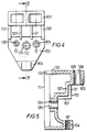
- the drill jig shown in Figs. 2 to 5 corresponds in functional principle to the drill jig shown in Fig. 1. For this reason like members have like references, but with the addition of 100. In what follows, basically only the differences from the drill jig in Fig. 1 will be described.
- the drill jig shown in Figs. 2 to 5 is suitable for the drilling of holes of difference diameters: the guide hole 135 and guide bore 138 having the smallest diameter, the guide hole 125 and the guide bore 128 having the largest diameter, and the guide hole 105 and the guide bore 108 having a middle diameter.
- the distance from the first abutment surface 107 and the second abutment surface 110 also differs in accordance with their diameters.
- the guide holes and guide bores also have insert bushes of hardened material.
- the only bushes shown in Fig. 5 are the bushes 126 and 129 for the guide hole 125 and the guide bore 128.
- the first abutment surface 107 and the second abutment surface 110 are formed by four parallel, rib-shaped projections 120, 121, 122 and 123 which merge into a step-shaped wall 137 (Fig. 5) of the drill jig 101.
- a cavity is disposed between the step-shaped wall 137, the outer surface 111, the top horizontal wall (Fig. 5) of the drill jig 101 and the end walls, one of which is shown in Fig. 2.
- the upper horizontal wall is formed with pin-receiving slots 130, 132 and 134, so that the cavity is accessible through such slots. As shown in Fig.
- the bottom of these pin-receiving slots is semi-circular, the centres 131, 133, 135 of such semicircles lying in the same plane as the longitudinal axis of the guide bore 108,128; 138 (cf. Fig. 3) and the longitudinal axis of the guide hole 105, 125; 135.
- the distance of the particular centre of the semicircle from the outer surface 111 is equal to the distance of the associated guide hole 105, 125 or 135 from the first abutment surface 107.
- the drill jig shown in Figs. 2 to 5 may be used in the same manner as the drill.jig shown in Fig. 1 for drilling holes in two workpieces, these holes corresponding to the holes 51 and 53 in the workpieces 50 and 52 shown in Fig. 1.
- Pin-receiving slots 130,132 and 134 are provided instead of one or more screwthreaded bores 12 (Fig. 1).
- the slots have the same function as the screwthreaded bores 12 in Fig. 1.
- One or more end-face bores are made in a workpiece, corresponding to the bore 51 in Fig. 1.
- the dowels to be used for the subsequent connection are then inserted in such bores.
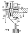
- the drill jig shown in Fig. 6 differs from those shown in Fig. 1 and Figs. 2 to 5 in respect of the location of the second abutment surface and the first abutment surface on the drill jig. However, since otherwise it is similar to the drill jig shown in Fig. 1, like members have given like references with the addition of 200.
- the drill jig 201 of the drill jig shown in Fig. 6 is substantially U-shaped and has a first arm 203, a second arm 202 and a third arm 204.
- a guide bore 208 which is bound by aligning bush 209, extends through the first arm 203.
- a guide hole 205 which is bound by aligning bush 206, extends through the second arm 202.
- the longitudinal axes of the guide bore 208 and the guide hole 205 extend perpendicular to one another in a common plane.
- a first abutment surface 207 which is flat, is arranged parallel with the longitudinal axis of the guide hole 205 and extends on the underside of the arm 203 between its free end and the boundary of the guide bore 208 adjacent thereto.
- a second abutment surface 210 is aligned to be parallel with the longitudinal axis of the guide bore 208 and is disposed on the inner side of the second arm 202.
- the second abutment surface 210 extends between the third arm 204 and the boundary of the guide hole 205 adjacent thereto. In this case also the distance between the longitudinal axis of the guide bore 208 and the second abutment surface 210 is equal to the distance between the longitudinal axis of the guide hole 205 and the first abutment surface 207.
- stops 236 which extend from the second arm 202 beyond the opposite boundary of the guide bore 208.
- a shank 214 of a screw clamp is inserted in a screwthreaded bore of the third arm 204.
- This screwthreaded bore corresponds to screwthreaded bore 117 in Fig. 5.
- the shank 214 has a gripping head 215 and a clamping member 216.
- the procedure for drilling holes into two workpieces corresponding to the holes 51 and 53 in the workpieces 50 and 52 in Fig. 12 is as follows.
- the workpiece 250 which is to be drilled at its end face, is caused to abut the first abutment surface 207.
- the stops 236 prevent the workpiece 250 from moving into the zone of the guide bore 208.
- the other workpiece 252, which abuts the lower surface of the workpiece 250 as viewed in Fig. 6, is caused to abut the second abutment surface 210.
- the two workpieces 250 and 252 may be rigidly interconnected by screw clamps (not shown).
- the screw clamp 214 extending through the third arm 204 merely attaches the drill jig to the workpieces 250, 252.
- the holes 251 and 253 can be made by drills guided by the guide hole 205 and the guide bore 208. This ensures that the holes 251 and 253 lie in a common plane and have the same diameter.
- the drill jig is removed, and the screw clamps holding the workpieces 250 and 252 together are loosened.
- the required dowels are inserted into the holes 253, and the workpiece 250 must then be merely pivoted through 90° anticlockwise (Fig. 6) to bring the holes 251 into engagement with the dowels in the holes 253.
- Fig. 6 the end face of the workpiece 250, which was previously abutting the second abutment surface 210, is in alignment with that surface of the workpiece 250 which was previously abutting the first abutment surface 207.
Landscapes
- Engineering & Computer Science (AREA)
- Mechanical Engineering (AREA)
- Drilling And Boring (AREA)
Claims (7)
Applications Claiming Priority (2)
| Application Number | Priority Date | Filing Date | Title |
|---|---|---|---|
| DE19838324646U DE8324646U1 (de) | 1983-08-27 | 1983-08-27 | Verduebelungs-bohrlehre |
| DE8324646U | 1983-08-27 |
Publications (2)
| Publication Number | Publication Date |
|---|---|
| EP0136080A1 EP0136080A1 (de) | 1985-04-03 |
| EP0136080B1 true EP0136080B1 (de) | 1988-03-02 |
Family
ID=6756543
Family Applications (1)
| Application Number | Title | Priority Date | Filing Date |
|---|---|---|---|
| EP84305803A Expired EP0136080B1 (de) | 1983-08-27 | 1984-08-24 | Bohrlehre für Dübelverbindungen |
Country Status (2)
| Country | Link |
|---|---|
| EP (1) | EP0136080B1 (de) |
| DE (2) | DE8324646U1 (de) |
Cited By (1)
| Publication number | Priority date | Publication date | Assignee | Title |
|---|---|---|---|---|
| EP2923785A1 (de) * | 2014-03-26 | 2015-09-30 | Miguel Angel Toledo Garcia | Bohrerpositionierer mit sicht |
Families Citing this family (15)
| Publication number | Priority date | Publication date | Assignee | Title |
|---|---|---|---|---|
| FR2603835B1 (fr) * | 1986-09-11 | 1989-08-25 | Francaise Metallurg | Procede et dispositif pour le percage de panneaux de bois en vue de leur assemblage par chevilles |
| FR2610861B2 (fr) * | 1986-09-11 | 1989-09-01 | Francaise Metallurg | Dispositif pour le percage de panneaux de bois en vue de leur assemblage par chevilles |
| US4798212A (en) * | 1986-11-17 | 1989-01-17 | Thomas Arana | Biopsy paddle with adjustable locator plate |
| FR2621269B1 (fr) * | 1987-10-05 | 1990-02-02 | Francaise Metallurg | Dispositif de positionnement de panneaux pour leur assemblage par vissage |
| GB2215245B (en) * | 1988-03-02 | 1992-04-22 | Newjig Ltd | Dowelling jig |
| US5222845A (en) * | 1992-06-22 | 1993-06-29 | Goldstein Steven M | Adjustable drill guide for door handles and locks |
| GB9402121D0 (en) * | 1994-02-04 | 1994-03-30 | Black & Decker Inc | Drilling device with an extension arm |
| TW396948U (en) * | 1999-07-11 | 2000-07-01 | Jiang Bau Min | Multi-purpose supplemental device used for drilling operation |
| CN103302334B (zh) * | 2012-03-09 | 2015-12-02 | 陕西飞机工业(集团)有限公司 | 柱形窝加工钻模 |
| CN104028809B (zh) * | 2014-06-03 | 2018-03-02 | 无锡易通精密机械股份有限公司 | 轴承外圈钻孔用定位工装 |
| CN104708079B (zh) * | 2015-03-26 | 2017-06-06 | 沈阳飞机工业(集团)有限公司 | 不同平面角度孔工装夹具及角度孔的加工方法 |
| CN109877365A (zh) * | 2017-12-06 | 2019-06-14 | 天津职业技术师范大学 | 拨叉组件上钻定位销孔专用夹具 |
| CN109262013A (zh) * | 2018-09-12 | 2019-01-25 | 中航成飞民用飞机有限责任公司 | 引孔装置 |
| CN117324664A (zh) * | 2023-08-28 | 2024-01-02 | 北京曙光航空电气有限责任公司 | 一种定位尺寸公差大的零件细长孔加工装置及加工方法 |
| CN117283019B (zh) * | 2023-10-16 | 2025-10-31 | 上海无线电设备研究所 | 一种带有双侧v形槽钣金组件的钻孔模具及其钻孔方法 |
Family Cites Families (1)
| Publication number | Priority date | Publication date | Assignee | Title |
|---|---|---|---|---|
| DE2750869A1 (de) * | 1977-11-14 | 1979-05-17 | Robert Wolff | Hilfsgeraet zum bohren der duebelloecher in miteinander zu verduebelnden brettern o.dgl. |
-
1983
- 1983-08-27 DE DE19838324646U patent/DE8324646U1/de not_active Expired
-
1984
- 1984-08-24 DE DE8484305803T patent/DE3469499D1/de not_active Expired
- 1984-08-24 EP EP84305803A patent/EP0136080B1/de not_active Expired
Cited By (1)
| Publication number | Priority date | Publication date | Assignee | Title |
|---|---|---|---|---|
| EP2923785A1 (de) * | 2014-03-26 | 2015-09-30 | Miguel Angel Toledo Garcia | Bohrerpositionierer mit sicht |
Also Published As
| Publication number | Publication date |
|---|---|
| EP0136080A1 (de) | 1985-04-03 |
| DE3469499D1 (en) | 1988-04-07 |
| DE8324646U1 (de) | 1984-01-26 |
Similar Documents
| Publication | Publication Date | Title |
|---|---|---|
| EP0136080A1 (de) | Bohrlehre für Dübelverbindungen | |
| CA2506924C (en) | Drilling guide for edge connections | |
| US5407306A (en) | Jig for boring dowel holes in true alignment with each other | |
| US4093394A (en) | Dowel hole-boring jig | |
| US5499667A (en) | Drill/cutting bit, and method of making structural joint | |
| US5466098A (en) | Drill bit guiding device | |
| US6158487A (en) | Miter joint keying system | |
| US4421442A (en) | Doweling jig | |
| IL73035A (en) | Tool-holding device and tool support | |
| US20010036389A1 (en) | Woodworking dowel master jig | |
| WO1999008846A1 (en) | Dowel jig | |
| US5423360A (en) | Apparatus for centering a work-piece relative to a cutting tool | |
| US4603719A (en) | Drilling and counterboring apparatus and method for toe fastening | |
| JPS61501139A (ja) | 第1部材を第2部材に連結する為の装置 | |
| GB2071537A (en) | Dowelling jig | |
| US4856944A (en) | Coupling between a tool head and a tool support | |
| US4730959A (en) | Edge joining fixture | |
| US4923340A (en) | Doweling jig | |
| EP0095339A1 (de) | Bohr- und Spannvorrichtung für Tischlerarbeiten | |
| US4492498A (en) | Drill bit jig | |
| US6244794B1 (en) | Clamp-type dowelling jig | |
| US6508613B2 (en) | Drill guide and method for drilling holes | |
| GB2288356A (en) | Drill clamp | |
| US4834593A (en) | Device for the drilling of wooden panels with a view to their assembly by dowels | |
| US5380117A (en) | Apparatus for the detachable coupling of gripping devices or corresponding tools on robot arms |
Legal Events
| Date | Code | Title | Description |
|---|---|---|---|
| PUAI | Public reference made under article 153(3) epc to a published international application that has entered the european phase |
Free format text: ORIGINAL CODE: 0009012 |
|
| 17P | Request for examination filed |
Effective date: 19841222 |
|
| AK | Designated contracting states |
Designated state(s): BE DE FR GB IT LU NL |
|
| 17Q | First examination report despatched |
Effective date: 19860612 |
|
| ITF | It: translation for a ep patent filed | ||
| GRAA | (expected) grant |
Free format text: ORIGINAL CODE: 0009210 |
|
| AK | Designated contracting states |
Kind code of ref document: B1 Designated state(s): BE DE FR GB IT LU NL |
|
| PG25 | Lapsed in a contracting state [announced via postgrant information from national office to epo] |
Ref country code: NL Effective date: 19880302 Ref country code: BE Effective date: 19880302 |
|
| REF | Corresponds to: |
Ref document number: 3469499 Country of ref document: DE Date of ref document: 19880407 |
|
| ET | Fr: translation filed | ||
| NLV1 | Nl: lapsed or annulled due to failure to fulfill the requirements of art. 29p and 29m of the patents act | ||
| PG25 | Lapsed in a contracting state [announced via postgrant information from national office to epo] |
Ref country code: LU Free format text: LAPSE BECAUSE OF NON-PAYMENT OF DUE FEES Effective date: 19880831 |
|
| PLBE | No opposition filed within time limit |
Free format text: ORIGINAL CODE: 0009261 |
|
| STAA | Information on the status of an ep patent application or granted ep patent |
Free format text: STATUS: NO OPPOSITION FILED WITHIN TIME LIMIT |
|
| 26N | No opposition filed | ||
| ITTA | It: last paid annual fee | ||
| PGFP | Annual fee paid to national office [announced via postgrant information from national office to epo] |
Ref country code: FR Payment date: 20010801 Year of fee payment: 18 |
|
| PGFP | Annual fee paid to national office [announced via postgrant information from national office to epo] |
Ref country code: DE Payment date: 20010802 Year of fee payment: 18 |
|
| PGFP | Annual fee paid to national office [announced via postgrant information from national office to epo] |
Ref country code: GB Payment date: 20010803 Year of fee payment: 18 |
|
| REG | Reference to a national code |
Ref country code: GB Ref legal event code: IF02 |
|
| PG25 | Lapsed in a contracting state [announced via postgrant information from national office to epo] |
Ref country code: GB Free format text: LAPSE BECAUSE OF NON-PAYMENT OF DUE FEES Effective date: 20020824 |
|
| PG25 | Lapsed in a contracting state [announced via postgrant information from national office to epo] |
Ref country code: DE Free format text: LAPSE BECAUSE OF NON-PAYMENT OF DUE FEES Effective date: 20030301 |
|
| GBPC | Gb: european patent ceased through non-payment of renewal fee |
Effective date: 20020824 |
|
| PG25 | Lapsed in a contracting state [announced via postgrant information from national office to epo] |
Ref country code: FR Free format text: LAPSE BECAUSE OF NON-PAYMENT OF DUE FEES Effective date: 20030430 |
|
| REG | Reference to a national code |
Ref country code: FR Ref legal event code: ST |