EP0136150A2 - Condenseur - Google Patents
Condenseur Download PDFInfo
- Publication number
- EP0136150A2 EP0136150A2 EP84306377A EP84306377A EP0136150A2 EP 0136150 A2 EP0136150 A2 EP 0136150A2 EP 84306377 A EP84306377 A EP 84306377A EP 84306377 A EP84306377 A EP 84306377A EP 0136150 A2 EP0136150 A2 EP 0136150A2
- Authority
- EP
- European Patent Office
- Prior art keywords
- condenser structure
- condenser
- connector
- heat exchange
- cooling fluid
- Prior art date
- Legal status (The legal status is an assumption and is not a legal conclusion. Google has not performed a legal analysis and makes no representation as to the accuracy of the status listed.)
- Withdrawn
Links
Images

Classifications
-
- F—MECHANICAL ENGINEERING; LIGHTING; HEATING; WEAPONS; BLASTING
- F28—HEAT EXCHANGE IN GENERAL
- F28B—STEAM OR VAPOUR CONDENSERS
- F28B1/00—Condensers in which the steam or vapour is separate from the cooling medium by walls, e.g. surface condenser
- F28B1/02—Condensers in which the steam or vapour is separate from the cooling medium by walls, e.g. surface condenser using water or other liquid as the cooling medium
Definitions
- the present invention relates to a condenser structure comprising a body, an end structure, U-shaped heat exchange tubes disposed within the body, at least one cooling fluid inlet connector, at least one condensate outlet connector and at least one cooling fluid outlet connector.
- Condenser structures of the kind defined above are used in numerous different applications, e.g. in distilling apparatus.
- the condenser structure prsently used has a distributor chamber from which there extends into the body part of the condenser a plurality of straight or U-shaped heat exchange tubes.
- the drawback of these prior art condenser structures is however that the flow velocity is very low and the condenser design requires very great amounts of cooling liquid for good heat exchange to be achieved.
- the heat exchange surface is formed of tube coils, whereby the flow velocity can be made as high as is required, because there are few flow paths compared with the U-tube construction.
- the drawback of these structures is that the coils have to be welded, with the welds located within the body part of the condenser. This gives rise to detrimental distensions and stresses which detract from the reliability of the condenser structure.
- the object of the invention is to achieve an improvement in condenser structures as known at present.
- the more detailed object of the invention is to provide a condenser structure in which the faults described above have been overcome.
- the aims of the invention are attained with a condenser structure which is mainly characterized in that the co-joining of the U-shaped heat exchange tubes for the purpose of dividing the flow path is arranged so that the juncture is located outside the end structure of the condenser structure.
- the condenser structure of the invention numerous significant advantages are gained. It has been understood in the condenser structure of the invention to make the flow path continuous, in other words to connect to a U-shaped heat exchange tube another U-shaped heat exchange tube, outside the body of the condenser structure. In this manner no harmful phenomena are caused in the structure by the welds. At the same time the design of the invention renders a high flow velocity possible, and this feature is achieved with a small quantity of coolant. Furthermore, in the condenser structure of the invention several different cooling liquids may be introduced. The upper part of the condenser structure is always cold enough. Gas venting is advantageously arranged to take place from the upper part of the condenser structure.
- the U-shaped condenser tube system is self-draining in that the flow is in a downward direction.
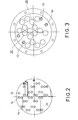
- the condenser structure 10 comprises a body 11 and an end structure 12.
- the cooling fluid flows into the condenser structure 10 through a connector 13.
- a plurality of U-shaped heat exchange tubes 14 Pure vapour is fed in through an inlet 15 whilst distillate is withdrawn through an outlet 16.
- a gas venting connector 17 In the upper part of the body 11 there is disposed a gas venting connector 17. Also provided are entry pipes 18 for liquid distillates and cooling fluid outlet pipes 19.
- the connecting of the heat exchange tubes 14, i.e., their joining with each other, has been solved in such a way that the flow path juncture 20 is located outside the end structure 12 of the condenser structure 10. There will then be no harmful welds at all within the body 11 of the condenser structure 10.
- the condenser structure of the invention makes a high flow velocity possible, but the design operates in spite of this faultlessly on an exceedingly small cooling liquid quantity.
- several different cooling fluids may be introduced to the condenser structure 10.
- the upper part of the body 11 of the condenser structure 10 stays cold all the time because gas venting takes place from the upper part by the connector 17. Naturally, it is possible in certain embodiments to assign another region within the condenser structure 10 to be the coldest of all.
Landscapes
- Engineering & Computer Science (AREA)
- Mechanical Engineering (AREA)
- General Engineering & Computer Science (AREA)
- Heat-Exchange Devices With Radiators And Conduit Assemblies (AREA)
- Cooling Or The Like Of Semiconductors Or Solid State Devices (AREA)
- Vaporization, Distillation, Condensation, Sublimation, And Cold Traps (AREA)
Applications Claiming Priority (2)
| Application Number | Priority Date | Filing Date | Title |
|---|---|---|---|
| FI833524A FI68525C (fi) | 1983-09-29 | 1983-09-29 | Kondensorkonstruktion |
| FI833524 | 1983-09-29 |
Publications (2)
| Publication Number | Publication Date |
|---|---|
| EP0136150A2 true EP0136150A2 (fr) | 1985-04-03 |
| EP0136150A3 EP0136150A3 (fr) | 1986-10-22 |
Family
ID=8517819
Family Applications (1)
| Application Number | Title | Priority Date | Filing Date |
|---|---|---|---|
| EP84306377A Withdrawn EP0136150A3 (fr) | 1983-09-29 | 1984-09-18 | Condenseur |
Country Status (4)
| Country | Link |
|---|---|
| EP (1) | EP0136150A3 (fr) |
| JP (1) | JPS6096888A (fr) |
| DK (1) | DK469084A (fr) |
| FI (1) | FI68525C (fr) |
Family Cites Families (7)
| Publication number | Priority date | Publication date | Assignee | Title |
|---|---|---|---|---|
| BE569535A (fr) * | ||||
| DE205196C (fr) * | ||||
| US1598040A (en) * | 1924-02-16 | 1926-08-31 | Berry Edwin Daniel | Cooler for cream and other liquids |
| US1671631A (en) * | 1926-08-09 | 1928-05-29 | Ercanbrack John Edward | Heat-transfer device |
| US2342838A (en) * | 1942-06-22 | 1944-02-29 | Lummus Co | Recovery of halogenated aromatic compounds |
| GB715162A (en) * | 1951-06-29 | 1954-09-08 | Lavals Angturbin Ab De | Improvements in surface condensers |
| US3162177A (en) * | 1962-12-28 | 1964-12-22 | Combustion Eng | Vapor generator having design provisions for the removal of high temperature vapor therefrom |
-
1983
- 1983-09-29 FI FI833524A patent/FI68525C/fi not_active IP Right Cessation
-
1984
- 1984-09-18 EP EP84306377A patent/EP0136150A3/fr not_active Withdrawn
- 1984-09-28 DK DK469084A patent/DK469084A/da not_active Application Discontinuation
- 1984-09-28 JP JP59203954A patent/JPS6096888A/ja active Pending
Also Published As
| Publication number | Publication date |
|---|---|
| FI68525B (fi) | 1985-06-28 |
| FI833524L (fi) | 1985-03-30 |
| FI68525C (fi) | 1985-10-10 |
| DK469084A (da) | 1985-03-30 |
| FI833524A0 (fi) | 1983-09-29 |
| DK469084D0 (da) | 1984-09-28 |
| EP0136150A3 (fr) | 1986-10-22 |
| JPS6096888A (ja) | 1985-05-30 |
Similar Documents
| Publication | Publication Date | Title |
|---|---|---|
| US5032373A (en) | Apparatus and process | |
| US3901269A (en) | Jacket construction for fluid flow fittings | |
| KR960008260A (ko) | 열교환코일 조립체 및 그 복합체 | |
| KR100209115B1 (ko) | 증기 발생기 | |
| CN1036494C (zh) | 加压水反应堆电站 | |
| US4173996A (en) | Heat exchanger arrangement for vaporization cooled transfomers | |
| EP0136150A2 (fr) | Condenseur | |
| US2965360A (en) | Heat exchangers | |
| KR850004799A (ko) | 내부식성 증기 발생기 | |
| US4813346A (en) | Wort cooking arrangement | |
| US3452518A (en) | Vapour separation systems | |
| US2893938A (en) | Electrolytic stabilization apparatus for water systems | |
| US1674850A (en) | Condenser | |
| US5515913A (en) | Anodically protected heat exchanger | |
| US2398184A (en) | Apparatus for distillation | |
| CN115394466B (zh) | 氚化水汽收集装置 | |
| US2034428A (en) | Heat interchange apparatus | |
| US3251404A (en) | Liquid metal heated steam generator | |
| JP2944698B2 (ja) | 分留塔 | |
| EP0462519A1 (fr) | Distributeur uniforme d'un fluide en deux couches dans des tubes d'échange de chaleur | |
| US4737281A (en) | Cold trap for purifying liquid sodium containing impurities | |
| US3390721A (en) | Multiple header feedwater heater | |
| US3809016A (en) | Steam generator with flat combustion chamber bottom | |
| EP0178545B1 (fr) | Générateur de vapeur | |
| CA1163627A (fr) | Echangeur de chaleur avec tubulure a baionnette |
Legal Events
| Date | Code | Title | Description |
|---|---|---|---|
| PUAI | Public reference made under article 153(3) epc to a published international application that has entered the european phase |
Free format text: ORIGINAL CODE: 0009012 |
|
| AK | Designated contracting states |
Designated state(s): CH DE FR GB LI NL SE |
|
| PUAL | Search report despatched |
Free format text: ORIGINAL CODE: 0009013 |
|
| AK | Designated contracting states |
Kind code of ref document: A3 Designated state(s): CH DE FR GB LI NL SE |
|
| 17P | Request for examination filed |
Effective date: 19870227 |
|
| 17Q | First examination report despatched |
Effective date: 19870605 |
|
| STAA | Information on the status of an ep patent application or granted ep patent |
Free format text: STATUS: THE APPLICATION IS DEEMED TO BE WITHDRAWN |
|
| 18D | Application deemed to be withdrawn |
Effective date: 19880302 |
|
| RIN1 | Information on inventor provided before grant (corrected) |
Inventor name: RUOKONEN, JOUKO Inventor name: LINNAKOSKI, JOUKO |