EP0136171A2 - Sackbündel, Verfahren und Vorrichtung zu seiner Herstellung - Google Patents
Sackbündel, Verfahren und Vorrichtung zu seiner Herstellung Download PDFInfo
- Publication number
- EP0136171A2 EP0136171A2 EP84306532A EP84306532A EP0136171A2 EP 0136171 A2 EP0136171 A2 EP 0136171A2 EP 84306532 A EP84306532 A EP 84306532A EP 84306532 A EP84306532 A EP 84306532A EP 0136171 A2 EP0136171 A2 EP 0136171A2
- Authority
- EP
- European Patent Office
- Prior art keywords
- bags
- bag
- hole
- bundle
- hand
- Prior art date
- Legal status (The legal status is an assumption and is not a legal conclusion. Google has not performed a legal analysis and makes no representation as to the accuracy of the status listed.)
- Withdrawn
Links
Images

Classifications
-
- B—PERFORMING OPERATIONS; TRANSPORTING
- B65—CONVEYING; PACKING; STORING; HANDLING THIN OR FILAMENTARY MATERIAL
- B65D—CONTAINERS FOR STORAGE OR TRANSPORT OF ARTICLES OR MATERIALS, e.g. BAGS, BARRELS, BOTTLES, BOXES, CANS, CARTONS, CRATES, DRUMS, JARS, TANKS, HOPPERS, FORWARDING CONTAINERS; ACCESSORIES, CLOSURES, OR FITTINGS THEREFOR; PACKAGING ELEMENTS; PACKAGES
- B65D33/00—Details of, or accessories for, sacks or bags
- B65D33/001—Blocks, stacks or like assemblies of bags
-
- B—PERFORMING OPERATIONS; TRANSPORTING
- B31—MAKING ARTICLES OF PAPER, CARDBOARD OR MATERIAL WORKED IN A MANNER ANALOGOUS TO PAPER; WORKING PAPER, CARDBOARD OR MATERIAL WORKED IN A MANNER ANALOGOUS TO PAPER
- B31B—MAKING CONTAINERS OF PAPER, CARDBOARD OR MATERIAL WORKED IN A MANNER ANALOGOUS TO PAPER
- B31B2155/00—Flexible containers made from webs
- B31B2155/003—Flexible containers made from webs starting from tubular webs
-
- B—PERFORMING OPERATIONS; TRANSPORTING
- B31—MAKING ARTICLES OF PAPER, CARDBOARD OR MATERIAL WORKED IN A MANNER ANALOGOUS TO PAPER; WORKING PAPER, CARDBOARD OR MATERIAL WORKED IN A MANNER ANALOGOUS TO PAPER
- B31B—MAKING CONTAINERS OF PAPER, CARDBOARD OR MATERIAL WORKED IN A MANNER ANALOGOUS TO PAPER
- B31B2160/00—Shape of flexible containers
- B31B2160/10—Shape of flexible containers rectangular and flat, i.e. without structural provision for thickness of contents
-
- B—PERFORMING OPERATIONS; TRANSPORTING
- B31—MAKING ARTICLES OF PAPER, CARDBOARD OR MATERIAL WORKED IN A MANNER ANALOGOUS TO PAPER; WORKING PAPER, CARDBOARD OR MATERIAL WORKED IN A MANNER ANALOGOUS TO PAPER
- B31B—MAKING CONTAINERS OF PAPER, CARDBOARD OR MATERIAL WORKED IN A MANNER ANALOGOUS TO PAPER
- B31B2170/00—Construction of flexible containers
- B31B2170/10—Construction of flexible containers interconnected
-
- B—PERFORMING OPERATIONS; TRANSPORTING
- B31—MAKING ARTICLES OF PAPER, CARDBOARD OR MATERIAL WORKED IN A MANNER ANALOGOUS TO PAPER; WORKING PAPER, CARDBOARD OR MATERIAL WORKED IN A MANNER ANALOGOUS TO PAPER
- B31B—MAKING CONTAINERS OF PAPER, CARDBOARD OR MATERIAL WORKED IN A MANNER ANALOGOUS TO PAPER
- B31B70/00—Making flexible containers, e.g. envelopes or bags
- B31B70/74—Auxiliary operations
- B31B70/92—Delivering
- B31B70/98—Delivering in stacks or bundles
- B31B70/988—Assembling or block-forming of bags; Loading bags on a mandrel
Definitions
- This invention relates to bags, and to a method of and an apparatus for, manufacture of such bags. More particularly, this invention relates to bundles of plastic bags, to the method of manufacture of such bundles and to an apparatus for manufacturing such bundles.
- Individual, flattened bags were generally piled, one atop another, up to a finite pile height.
- As a check-out person grasped an uppermost bag from such a pile it was often difficult (for such a person) quickly to engage in a bag-loading procedure which included removing the uppermost bag from the pile, locating the uppermost bag opening, opening the bag and positioning the bag for receipt of goods.
- Such a bagging procedure thus was often inefficient, time consuming and expensive for the merchandiser.
- such bags had generally been made of paper.
- Packaging goods in plastic bags is now quickly becoming the preferred method of packaging merchandise.
- a plastic handled bag has generally been encountered by the public at a variety of check-out counters.
- many of such plastic bags are generally known to be difficult quickly to open and load with goods. It is currently thought, for example, that charge builds up on the sidewalls of many plastic bags, such charge buildup causing the bag sidewalls to adhere together.
- a more specific object is to provide a bundle of such bags, such a bag bundle including a plurality of such bags uniformly disposed and fastened together at one end thereof.
- a further object is to provide such a bundle having an uppermost or closest bag wherein a mouth or opening of such a bag is readily graspable for opening such bag.
- Yet another object is to provide such a bundle wherein any individual bag (but preferably the uppermost or closest bag) is readily removable, as by a flip of the wrist, from the remainder of bags in the bundle.
- a related object is to'provide a method for the manufacture of such a bag and bag bundle.
- Another related object is to provide an apparatus for the manufacture of such a bag and bag bundle.
- the bundle comprises a pluraity of plastic bags.
- Each such bag includes a first sidewall, a second sidewall integral with the first sidewall at lateral end portions thereof, a closed bottom, an opening in distal relation to the bottom and a tab.
- a longitudinal end portion of the first and second sidewalls defines the opening.
- the tab is integral with at least one of the first and second sidewall end portions adjacent the opening. The tab, moreover, is readily separable from such sidewall end portion because of the presence of a plurality of perforations formed in such sidewall end portion adjacent the opening. Only one of the first and second sidewalls includes a hand hole formed through such.
- the bags are affixed together at their tabs in a stacked, folded manner, all such bag hand holes being uniformly disposed.
- the affixed tabs preferably include at least one support hole therethrough for securing the bag bundle to a support.
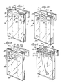
- a first embodiment of the bag bundle 10 (FIG. 1) comprises a plurality of (preferably from about 50 to about 100) joined, collapsed bags 12.
- the bags 12 are made of plastic and preferably have relatively thin walls.
- Each such bag 12 includes a first or forward sidewall 14 and a second or rearward sidewall 16 integral with the first sidewall 14 at lateral end portions thereof (FIGS. 2-4). Each such bag 12 further includes a bottom 18 formed by joining together the lower longitudinal end portions of the forward and rearward sidewalls 14, 16 along a transverse line 19 (FIG. 3). Each such bag 12 yet further includes a mouth or opening 20 in distal relation to the bottom 18 (FIGS. 2, 3).
- Each such bag 12 additionally includes a tab 24 (FIG. 1).
- the tab 24 is integral with first and second sidewall upper longitudinal 1nd portions adjacent the opening 20 (FIG. 2).
- Such sidewall upper longitudinal end portion is separable from its tab 24 because each such bag 12 further includes a linear perforated boundary or margin 26 (FIG. 1) for separating the bag 12 from the tab 24.
- the sidewalls 14, 16 preferably include longitudinally-disposed inwardly-folded (or gusseted) integral side panels 22 (FIG. 4) at lateral end portions thereof.
- Only one (preferably the forward sidewall 14) of the sidewalls 14, 16 includes a hand hole 28 (FIG. 3) formed through such sidewall 14, large enough for readily inserting the fingers of a hand of a grasper (FIG. 2) into the opening 20 intermediate the forward and rearward sidewalls 14, 16.
- the perforations of the boundary 26 are spaced such that when the tab 24 is held securely by the grasper a quick flip of the wrist (after the fingers have been inserted intermediate the forward and rearward sidewalls 14, 16) provides sufficient force for removing such a grasped bag 12 from the tab 24.
- the gusseted side panels 22 serve to space the sidewalls 14 and 16 from each other to facilitate inserting of the fingers into the opening 20 and behind the forward wall 14.
- the perforated margin 26 overlies an upper edge of the hand hole 28 (FIG. 1). Accordingly, when the user inserts his fingers through the hand hole 28 (of a bag 12) for the purpose of removing such a grasped bag 12 from the bundle 10 (FIG. 2), the hand hole 28 of the bag 12 (FIG. 3), now removed from the bundle 10, provides the bag 12 with a notch 29 (FIG. 33) along the upper longitudinal end portion of only the forward sidewall 14.
- the inertia or attraction as between the forward and rearward sidewalls 14, 16, surprisingly, is readily overcome by a quick thrust of the fingers through the hand hole 28.
- the fingers initially separate upper portions of the forward and rearward sidewalls 14, 16, and subsequent downward disposition of the fingers permits the user to grasp the forward sidewall 14 (preferably along the hand hole 28) for removing the bag 12 from the tab 24 as above described.
- the bags 12 of the first embodiment of the bag bundle 10 are joined together in a manner such that the tabs 24 are one atop another, and such that the hand holes 28 are uniformly disposed, i.e., preferably directed toward the user (FIG. 2).
- the tabs 24 are fastened together preferably along an upper transverse line 30 (FIGS. 1, 2) located intermediate the perforated margin 26 and an upper edge of each tab 24, thereby forming the first embodiment of the bundle 10.
- the tabs 24 of the first embodiment moreover, include punched holes 32 preferably through spaced opposite end portions of the tabs joined 24, and further preferably centered on the transverse line 30 for supporting the bundle 10 in a known manner using hooks 34 and a support structure 36 (FIG. 1).
- the hooks 34 are preferably fastened to the support structure 36 by screws 35.
- the legs 33A are preferably mounted into a counter top 39 in an upright manner.
- a second embodiment of a structure 36B (FIG. 6A), also particularly useful for. supporting the bag bundle 10, similarly comprises hooks 34A, a single leg 33B and a metal plate 37B'serving a function similar. to that of the metal plate 37A.
- the leg 33B similarly is preferably mounted into the counter top 39 in an upright manner.
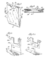
- the upper longitudinal edge portions of the forward and rearward sidewalls 14A, 16A respectively include a hand hole 28A and an arcuate tab 24A.
- the tab 24A integral only with the rearward sidewall 16A, is separable from the rearward sidewall 16A along an arcuate perforated boundary or margin 26A.
- Bags 12A (of the second embodiment of the bag bundle 10A) are stacked, one atop another, in a manner such that the tabs 24A are one atop another, and such that the hand holes 28A are uniformly disposed.
- the stacked tabs 24A moreover, preferably include at least one hole 32A formed therethrough for supporting the bundle in 10A (substantially as described above, using a single hook 34).
- the tabs 24A are joined together preferably along the circumference of the holes 32A.
- the first and second sidewalls 14A, 16A further include elongated patches 41 (preferably plastic) which respectively have been affixed to the first and second sidewalls 14A, 16A intermediate the side panels 22.
- the patches 41 are located proximate to the hand hole 28A and tab 24A and are transversely disposed relative to the side panels 22.
- the third embodiment further preferably includes a second hand hole 43 (FIG. lB) formed through the first and second sidewalls 14A, 16A and centered on the patches 41.
- the second hand holes 43 are transversely disposed relative to the side panels 22, and serves as a means for carrying the bag 12B when such bag 12B has been removed from its bag bundle 10B and filled with merchandise.
- the patches 41 serve as a reinforcement for eliminating tearing of the sidewalls l4A, 16A. Accordingly, the thickness of the patches 41 is sufficient for accomplishing such a purpose.
- the bags 12, 12A and 12B are preferably made of a relatively thin gauge plastic, and are preferably individually heat sealed'at the transverse line 19 (FIG. 4) thereby providing each bag 12, 12A and 12B with its respective closed bottom 18.
- the bags 12, 12A and 12B of each respective bag bundle 10, 10A and 10B, moreover, are fastened together, using commercially available heat-welding apparatus, either along the line 30 or along the circumference of the holes 32A.
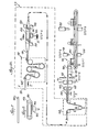
- an extruder 38 which receives plastic material from a source (not shown), extrudes (step 1) a molten form of the plastic material.
- the extruded plastic material assumes the shape or form of a tube or sleeve 40.
- Feed rollers 42 (within a tube-transfer station 45) transfer the extruded tube 40 from the extruder 38 to heat sealers 44.
- the feed rollers.42 of the tube-transfer station 45 serve to flatten the tube 40 as the tube is advanced past the heat sealers 44 .
- the heat sealers 44 are spaced above and below the extruded tube 40, and are .
- step 2 the extruded tube 40 into a plurality of (in FIG. 5, for example, 3) relatively narrower, longitudinally-joined tubes 46.
- the tubes 46 are then drawn past cutters 48 which cut (step 3) the tubes 46 along a margin or region 50 where such tubes 46 had been joined.
- Advancing rollers 49 then advance individual tubes 46 (now servered one from another) through a tension-adjusting station 52 preferably comprising five rollers (FIG. 5A) so that each tube 46 can be punched on one side only (FIG. 5A: step 4).
- FIG. 5A it will be seen that within each tube 46 an internal mandrel 54 having an anvil 56 is supported within the tube 46 by support rollers 58.
- the internal mandrel 54 separates the walls of the tube 46, and changes the shape of the tube 46 from substantially flat (FIG. 7) to relatively open (FIG. 8).
- A'punch 60 external to the tube 46, at predetermined time intervals, strikes the mandrel anvil 56 forming the hand hole 28 through one side only of the tube 46 (see FIG. 5).
- An indexing station 62 advances each tube 46 from its respective mandrel 54 to a folding station 64 where guiding vanes 66 (FIGS. 5, 5A) cause folds or gussets to be formed (step 5) in the lateral sides of each tube 46. (These folds or gussets become the side panels 22 when the tubes 46 are later formed into bags 12, 12A or 128.)
- the indexing station 62 serves to flatten the tubes 46 as they are drawn over their respective mandrels 54. (As between FIGS. 5 and 5A, the tension-adjusting station 52, mandrels 54 and indexing station 62 are included within an area 63.)
- each tube 46 is advanced by advancing rollers 68 to heat sealers 70 and cutters 72.
- the function of the heat sealers 70 is to heat seal transversely-disposed, longitudinally-spaced portions of each tube 46, and the function of the cutters 72 is to cut (step 6) each such tube 46 along these transversely-disposed, heat-sealed portions.
- Each such tube 46 is cut along a longitudinal end portion which is. in distal relation to the hand hole 28. See FIG. 5.
- Severed tubes 46 are conveyed by a conveyer 74 from the heat sealers 70 and cutters 72 to a stacker 76 which causes the severed tubes 46 to become stacked vertically (step 7).
- the advancing rollers 68 serve to advance the unsevered tubes 46 past the heat sealers 70 and cutters 72.
- the heat sealers 70 and cutters 72 perform their respective functions upon the tubes 46 at predetermined time intervals.
- the advancing rollers 68, heat sealers 70 and cutters 72 moreover, cooperate in a manner such that a leading end portion of the unsevered tubes 46 is permitted to be advanced onto the conveyor 74 before the cutters 72 cut such leading end portions from the remainder of each tube 46.
- a leading longitudinal end portion of the severed tubes 46 are heat sealed together (step 8) at the transverse line 30 (FIGS. 1, 5) by a heat sealer 78 (FIGS. 5, 5A).
- a conveyer 80 which operates at predetermined time intervals in cooperation with the stacker 76, receives the severed tubes 46 from the conveyor 74 and permits a quantity (preferably from about 50 to about 100) to.accumulate as to each pile of severed tubes 46 (there are 3 such piles: see FIG. 5) before advancing the stacks of tubes 46 from the stacker 76 to the heat sealer 78.
- the conveyor 80 transfers the joined and severed tubes 46, now unfinished bag bundles 10, to a punch 82 which punches and cuts (step 9) the bag bundles 10, through the leading end portions thereof thereby forming the perforated boundaries or margins 26 and.the tabs 24.
- the punch 82 preferably forms the linear perforated margin 26 when the apparatus (of the present invention) is used to form the first embodiment (FIG. 1) of the present invention.
- the punch 82 moreover, preferably forms the arcuate perforated margin 26A when the apparatus is used to form the second and third embodiments (FIGS. lA, IB).
- the punch 82- is used for forming the holes 32 or 32A through the tabs 24 or 24A of the first or second and third embodiments of the bundles 10 or 10A and 10 B of the present invention.
- the holes 32 are preferably spaced at opposite end portions of the transverse line 30 for additional support of the bag bundle 10 by the hooks 34.
- the punch 82 moreover, cuts each bag 12A or 12B at the upper or leading longitudinal edge 27 thereof (FIGS. lA, lB).
- the punch 82 includes means for hot punching the tabs 24A together thereby forming the holes 32A whereby the tabs 24A are joined together at the circumferences of the holes 32A.
- FIGS. 5 and 5a show forming the hand holes and severing the tube at the leading margins of the bags, but in many instances, it may be preferred to arrange the tooling so as to form the hand holes and sever the tube at the trailing end of the bags.
- the tooling at steps 7, 8 and 9 would be correspondingly relocated. Accordingly, such alternatives, changes and modifications are to be considered as forming a part of the invention insofar as they fall within the spirit and scope of the appended claims.
Landscapes
- Engineering & Computer Science (AREA)
- Mechanical Engineering (AREA)
- Bag Frames (AREA)
- Making Paper Articles (AREA)
Applications Claiming Priority (2)
| Application Number | Priority Date | Filing Date | Title |
|---|---|---|---|
| US53565283A | 1983-09-26 | 1983-09-26 | |
| US535652 | 1983-09-26 |
Publications (2)
| Publication Number | Publication Date |
|---|---|
| EP0136171A2 true EP0136171A2 (de) | 1985-04-03 |
| EP0136171A3 EP0136171A3 (de) | 1986-06-11 |
Family
ID=24135183
Family Applications (1)
| Application Number | Title | Priority Date | Filing Date |
|---|---|---|---|
| EP84306532A Withdrawn EP0136171A3 (de) | 1983-09-26 | 1984-09-26 | Sackbündel, Verfahren und Vorrichtung zu seiner Herstellung |
Country Status (1)
| Country | Link |
|---|---|
| EP (1) | EP0136171A3 (de) |
Cited By (13)
| Publication number | Priority date | Publication date | Assignee | Title |
|---|---|---|---|---|
| US4708243A (en) * | 1986-05-06 | 1987-11-24 | Nailon Wayne M | Portable bag storage assembly |
| DE3701184A1 (de) * | 1986-08-08 | 1988-02-11 | Schisler Robert Cee Sa | Biegsame tasche zur aufnahme von artikeln |
| EP0256375A1 (de) * | 1986-08-19 | 1988-02-24 | WindmÀ¶ller & Hölscher | Verfahren und Vorrichtung zur Herstellung von Beutelstapeln |
| DE3637231A1 (de) * | 1986-11-03 | 1988-05-05 | Stiegler Maschf Gmbh | Beutelstapel aus aufeinanderliegenden kunststoffbeuteln |
| EP0267706A1 (de) * | 1986-10-24 | 1988-05-18 | William F. Brown | Beutelstapel und Verfahren und Vorrichtung zum Herstellen |
| WO1988006092A1 (fr) * | 1987-02-14 | 1988-08-25 | Stiegler Gmbh Maschinenfabrik | Procede de production de paquets de sachets regroupes en bloc en film plastique lateralement soudes |
| DE3711165A1 (de) * | 1987-04-02 | 1988-10-20 | Stiegler Maschf Gmbh | Verfahren zum herstellen von tragebeuteln aus kunststoffolie mit seitennaht |
| DE3721303A1 (de) * | 1987-06-27 | 1989-01-05 | Stiegler Maschf Gmbh | Verfahren zum herstellen von tragebeuteln mit einer geschweissten bodennaht |
| US4796759A (en) * | 1987-12-29 | 1989-01-10 | C.E.E. Compagnie Europeene Des Emballages | Bundle of supple bags, made of fine material such as plastics material or paper |
| EP0301149A1 (de) * | 1987-07-31 | 1989-02-01 | Luigi Frateschi | Spender für Kunststoffbeutel |
| FR2618761A1 (fr) * | 1987-07-31 | 1989-02-03 | Frateschi Luigi | Distributeur de sacs plastiques |
| GB2337507A (en) * | 1998-05-18 | 1999-11-24 | Lemo Maschb Gmbh | Interconnected block of bags and their manufacture |
| US6880310B2 (en) | 2002-09-24 | 2005-04-19 | Yakima Packaging Automation, Inc. | Method for automatic bale bag loading |
Family Cites Families (7)
| Publication number | Priority date | Publication date | Assignee | Title |
|---|---|---|---|---|
| BE622457A (de) * | ||||
| DE1058929B (de) * | 1954-04-20 | 1959-06-04 | Milprint Inc | Schlauchartiger Behaelter aus biegsamem Material |
| DE1133667B (de) * | 1961-03-15 | 1962-07-19 | Munksjoe Aktie Bolag | Behaelter fuer Muell, Kehricht od. dgl. in Form einer Tuete |
| US3509799A (en) * | 1967-08-04 | 1970-05-05 | Crown Zellerbach Corp | Bag-forming method |
| BE805713A (fr) * | 1973-10-05 | 1974-02-01 | Printex | Procede pour la fabrication de liasses de sacs en matiere plastique et machine pour la mise en oeuvre de ce procede |
| FR2267200A1 (en) * | 1974-04-13 | 1975-11-07 | Lehmacher Hans | Appts for making bag stacked in stack block - from thermoplastic synthetic resin foil |
| US4201299A (en) * | 1978-06-06 | 1980-05-06 | Bumgarner Robert L | Bag |
-
1984
- 1984-09-26 EP EP84306532A patent/EP0136171A3/de not_active Withdrawn
Cited By (20)
| Publication number | Priority date | Publication date | Assignee | Title |
|---|---|---|---|---|
| US4708243A (en) * | 1986-05-06 | 1987-11-24 | Nailon Wayne M | Portable bag storage assembly |
| DE3701184A1 (de) * | 1986-08-08 | 1988-02-11 | Schisler Robert Cee Sa | Biegsame tasche zur aufnahme von artikeln |
| FR2602490A1 (fr) * | 1986-08-08 | 1988-02-12 | Schisler Cie Europ Emballages | Sac souple pour la reception d'articles |
| EP0256375A1 (de) * | 1986-08-19 | 1988-02-24 | WindmÀ¶ller & Hölscher | Verfahren und Vorrichtung zur Herstellung von Beutelstapeln |
| DE3700914A1 (de) * | 1986-08-19 | 1988-02-25 | Windmoeller & Hoelscher | Beutelstapel sowie verfahren und vorrichtung zu seiner herstellung |
| US4903839A (en) * | 1986-08-19 | 1990-02-27 | Windmoller & Holscher | Stack of bags each having congruent cutouts and perforated lines |
| EP0267706A1 (de) * | 1986-10-24 | 1988-05-18 | William F. Brown | Beutelstapel und Verfahren und Vorrichtung zum Herstellen |
| DE3637231A1 (de) * | 1986-11-03 | 1988-05-05 | Stiegler Maschf Gmbh | Beutelstapel aus aufeinanderliegenden kunststoffbeuteln |
| WO1988006092A1 (fr) * | 1987-02-14 | 1988-08-25 | Stiegler Gmbh Maschinenfabrik | Procede de production de paquets de sachets regroupes en bloc en film plastique lateralement soudes |
| DE3704662A1 (de) * | 1987-02-14 | 1988-08-25 | Stiegler Maschf Gmbh | Verfahren zum herstellen von verblockten packen aus beuteln mit seitennaht |
| US4811418A (en) * | 1987-04-02 | 1989-03-07 | Stiegler Gmbh Maschinenfabrik | Method for the manufacture of plastic bags with welded side seams |
| DE3711165A1 (de) * | 1987-04-02 | 1988-10-20 | Stiegler Maschf Gmbh | Verfahren zum herstellen von tragebeuteln aus kunststoffolie mit seitennaht |
| DE3721303A1 (de) * | 1987-06-27 | 1989-01-05 | Stiegler Maschf Gmbh | Verfahren zum herstellen von tragebeuteln mit einer geschweissten bodennaht |
| FR2618761A1 (fr) * | 1987-07-31 | 1989-02-03 | Frateschi Luigi | Distributeur de sacs plastiques |
| EP0301149A1 (de) * | 1987-07-31 | 1989-02-01 | Luigi Frateschi | Spender für Kunststoffbeutel |
| FR2622548A2 (fr) * | 1987-07-31 | 1989-05-05 | Frateschi Luigi | Distributeur de sacs plastiques |
| US4796759A (en) * | 1987-12-29 | 1989-01-10 | C.E.E. Compagnie Europeene Des Emballages | Bundle of supple bags, made of fine material such as plastics material or paper |
| GB2337507A (en) * | 1998-05-18 | 1999-11-24 | Lemo Maschb Gmbh | Interconnected block of bags and their manufacture |
| GB2337507B (en) * | 1998-05-18 | 2002-08-28 | Lemo Maschb Gmbh | Thermoplastic foil bag and method and apparatus for the manufacture thereof |
| US6880310B2 (en) | 2002-09-24 | 2005-04-19 | Yakima Packaging Automation, Inc. | Method for automatic bale bag loading |
Also Published As
| Publication number | Publication date |
|---|---|
| EP0136171A3 (de) | 1986-06-11 |
Similar Documents
| Publication | Publication Date | Title |
|---|---|---|
| US4995860A (en) | Easy opening bag pack and supporting rack system and fabricating method | |
| US4181069A (en) | Method for producing double streams of side-welded bags in heat-welded pad form | |
| US4981216A (en) | Easy opening bag pack and supporting rack system and fabricating method | |
| US4785938A (en) | Thermoplastic bag pack | |
| US4877473A (en) | Method of making a bag pack | |
| US4889523A (en) | Tearable package of synthetic thermoplastic foil and device and method for producing the same | |
| EP0136171A2 (de) | Sackbündel, Verfahren und Vorrichtung zu seiner Herstellung | |
| US8141329B2 (en) | Method and apparatus for making packages with internal headers from preformed bags | |
| US6769229B2 (en) | Method for manufacturing flexible packages having slide closures | |
| US20040161172A1 (en) | Reclosable bag having wicket flap and slider-actuated string zipper | |
| EP0312393A1 (de) | Leicht zu öffnender weicher Beutel sowie Verfahren und Gerät zu dessen Herstellung | |
| US6530870B2 (en) | Methods of manufacturing reclosable packages; and packages made thereby | |
| US5465845A (en) | Grocery bag dispensing and loading system | |
| US4909636A (en) | Coupon for T-shirt grocery bag | |
| US4816104A (en) | Methods and systems for preparing flat-bottom thermoplastic sack | |
| US20020134702A1 (en) | Bag blocks | |
| AU2002255800A1 (en) | Method and apparatus for making gusseted package | |
| EP0199508B1 (de) | Verfahren zur Vorbereitung von thermoplastischen Beuteln mit flachem Boden | |
| US5865313A (en) | Plastic bag pack system with novel handle apertures | |
| US4790437A (en) | Thermoplastic bag, bag pack and method of making the same | |
| US4571235A (en) | Methods for preparing flat-bottom thermoplastic sack and systems therefore | |
| US4744200A (en) | Thermoplastic bag pack with single tab suspension | |
| US6186933B1 (en) | Plastic bag manufacturing process | |
| DE3377477D1 (en) | Method and device for manufacturing and stocking thermoplastic bags | |
| US6508588B1 (en) | Plastic film bag stack with corner holes separated by perforations from a flap having stacking openings |
Legal Events
| Date | Code | Title | Description |
|---|---|---|---|
| PUAI | Public reference made under article 153(3) epc to a published international application that has entered the european phase |
Free format text: ORIGINAL CODE: 0009012 |
|
| AK | Designated contracting states |
Designated state(s): BE CH DE FR GB LI SE |
|
| PUAL | Search report despatched |
Free format text: ORIGINAL CODE: 0009013 |
|
| AK | Designated contracting states |
Kind code of ref document: A3 Designated state(s): BE CH DE FR GB LI SE |
|
| 17P | Request for examination filed |
Effective date: 19861105 |
|
| 17Q | First examination report despatched |
Effective date: 19870722 |
|
| STAA | Information on the status of an ep patent application or granted ep patent |
Free format text: STATUS: THE APPLICATION IS DEEMED TO BE WITHDRAWN |
|
| 18D | Application deemed to be withdrawn |
Effective date: 19881025 |