EP0136228A2 - Isolierschaltung mit optoelektronischem Koppler - Google Patents
Isolierschaltung mit optoelektronischem Koppler Download PDFInfo
- Publication number
- EP0136228A2 EP0136228A2 EP84401817A EP84401817A EP0136228A2 EP 0136228 A2 EP0136228 A2 EP 0136228A2 EP 84401817 A EP84401817 A EP 84401817A EP 84401817 A EP84401817 A EP 84401817A EP 0136228 A2 EP0136228 A2 EP 0136228A2
- Authority
- EP
- European Patent Office
- Prior art keywords
- circuit
- emitting diode
- diode
- light emitting
- isolator
- Prior art date
- Legal status (The legal status is an assumption and is not a legal conclusion. Google has not performed a legal analysis and makes no representation as to the accuracy of the status listed.)
- Granted
Links
- 230000005693 optoelectronics Effects 0.000 title claims description 10
- 239000003990 capacitor Substances 0.000 claims description 7
- 230000010287 polarization Effects 0.000 claims description 6
- 238000004519 manufacturing process Methods 0.000 abstract description 3
- 238000002955 isolation Methods 0.000 description 5
- 235000021183 entrée Nutrition 0.000 description 3
- 238000000429 assembly Methods 0.000 description 2
- 238000001228 spectrum Methods 0.000 description 2
- 230000000712 assembly Effects 0.000 description 1
- 150000001875 compounds Chemical class 0.000 description 1
- 238000010586 diagram Methods 0.000 description 1
- 238000005259 measurement Methods 0.000 description 1
- 230000003071 parasitic effect Effects 0.000 description 1
- 108091008695 photoreceptors Proteins 0.000 description 1
- 230000000135 prohibitive effect Effects 0.000 description 1
- 238000011144 upstream manufacturing Methods 0.000 description 1
Images

Classifications
-
- H—ELECTRICITY
- H03—ELECTRONIC CIRCUITRY
- H03K—PULSE TECHNIQUE
- H03K17/00—Electronic switching or gating, i.e. not by contact-making and –breaking
- H03K17/51—Electronic switching or gating, i.e. not by contact-making and –breaking characterised by the components used
- H03K17/78—Electronic switching or gating, i.e. not by contact-making and –breaking characterised by the components used using opto-electronic devices, i.e. light-emitting and photoelectric devices electrically- or optically-coupled
- H03K17/795—Electronic switching or gating, i.e. not by contact-making and –breaking characterised by the components used using opto-electronic devices, i.e. light-emitting and photoelectric devices electrically- or optically-coupled controlling bipolar transistors
-
- H—ELECTRICITY
- H04—ELECTRIC COMMUNICATION TECHNIQUE
- H04B—TRANSMISSION
- H04B10/00—Transmission systems employing electromagnetic waves other than radio-waves, e.g. infrared, visible or ultraviolet light, or employing corpuscular radiation, e.g. quantum communication
- H04B10/80—Optical aspects relating to the use of optical transmission for specific applications, not provided for in groups H04B10/03 - H04B10/70, e.g. optical power feeding or optical transmission through water
- H04B10/801—Optical aspects relating to the use of optical transmission for specific applications, not provided for in groups H04B10/03 - H04B10/70, e.g. optical power feeding or optical transmission through water using optical interconnects, e.g. light coupled isolators, circuit board interconnections
- H04B10/802—Optical aspects relating to the use of optical transmission for specific applications, not provided for in groups H04B10/03 - H04B10/70, e.g. optical power feeding or optical transmission through water using optical interconnects, e.g. light coupled isolators, circuit board interconnections for isolation, e.g. using optocouplers
Definitions
- the subject of the present invention is an optoelectronic coupler isolator circuit. It finds an application in electronics, in particular in the production of analog or digital equipment. With regard to the latter, mention may be made, for example, of digital audio-frequency codec-decoders ("codecs").
- Audio broadcasting equipment as well as most public address equipment, includes input and output transformers, the role of which is to provide galvanic isolation between the various sub-assemblies of the audio frequency chain.
- galvanic isolation can be obtained by optoelectronic couplers. These devices include a light emitting diode disposed opposite a photodetector, a bias circuit of the light emitting diode and an output amplifier connected to the photodetector.
- Isolation transformers are reserved for the professional field (broadcasting, production, measurements), or semi-professional (sound system), because of their high price.
- Components with professional-type performance are particularly expensive, especially if they have to accept a large signal amplitude, of the order of twenty decibels. For such levels, distortion at low frequencies quickly becomes prohibitive, due to the saturation of the magnetic core, unless the volume of the carcass is increased.
- an iso transformer - Lely professional 600-n- impedance occupies a volume of 0.2 to 0.4 liters, and its price is between 400 and 600F (1983); moreover, due to the technology used, this price can only increase.
- the optoelectronic couplers do not have these drawbacks, it should however be emphasized that the presence of a continuous polarization of the emitting diode is very restrictive in the case of equipment with several inputs: it is then necessary to transport a line d by input, which is inconvenient. Furthermore, the conventional connection diagram of this component does not ensure compatibility with the magnetic isolation transformers possibly used elsewhere, and this insofar as the polarization of the emitting diode must be ensured by the upstream circuit.
- the object of the invention is precisely to remedy this drawback by proposing an optoelectronic circuit which can replace high-impedance input transformers, particularly in audio frequency equipment.
- This circuit performs the same functions as an isolation transformer with at least equal dynamics, and a smaller footprint and price.
- an optoelectronic coupler is used according to the invention, the bias circuit of which is specific and is of the high-frequency type; this eliminates the need to transport a special power supply line for each of the audio frequency inputs to polarize the diodes of the couplers used.
- the rectifier circuit comprises a diode or a diode bridge and a capacitor.
- the bias circuit includes a resistor and a capacitor.
- the high frequency voltage source is constituted by means belonging to the equipment on which the isolator circuit is installed.
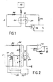
- the isolator circuit illustrated in FIG. 1 is of the type which includes an optoelectronic coupler 10, composed of a transmitting diode DE disposed opposite a photoreceptive diode DR, a circuit 12 for biasing the transmitting diode DE, an input signal E connected to the emitting diode by a resistor RE and an output amplifier 14 connected to the photoreceptor diode by an output resistor RS and a signal output S.
- an optoelectronic coupler 10 composed of a transmitting diode DE disposed opposite a photoreceptive diode DR, a circuit 12 for biasing the transmitting diode DE, an input signal E connected to the emitting diode by a resistor RE and an output amplifier 14 connected to the photoreceptor diode by an output resistor RS and a signal output S.
- the originality of the circuit of the invention lies in the structure of the bias circuit. It is illustrated by FIG. 2.
- the isolator shown has a circuit for biasing the light-emitting diode DE which comprises a high frequency voltage source 20 connected to a high frequency transformer TR and a rectifier circuit 22 inserted between this transformer and the diode photo emitter.
- the rectifier circuit 22 includes a diode D, a capacitor C and a resistor RP.
- the operating principle of this bias circuit is as follows.
- the low impedance transformer TR transmits the high frequency bias signal to the rectifier circuit.
- the frequency used is typically between 2 and 20 MHz.
- a 5-pin DIL format transformer, of the MCL T4-1 type is more than enough.
- the fact of using a high frequency has the advantage, compared to the use of a conventional floating power supply, of not generating any parasitic ripple in the audio frequency spectrum.
- a simpler rectifier circuit can be used by forgoing the diode D: a simple integrator circuit with resistance and with capacitor can be inserted between the transformer and the emissive diode.
- the only condition to be respected is that the high cut frequency f A of the audio spectrum is much lower than if R and C are the values of the resistive and capacitive elements.
- an adapter circuit 21 can be used (in dashed lines in FIG. 2), for reasons of compatibility between the source 20 and the rest of the circuit. It can for example be a buffer circuit in TTL ("Transistor-Transistor-Logic").
- the amplifier 14 can be of the voltage-voltage type. His gain is high.
- the RP resistor adjusts the bias current of the DE diode and the R4 resistor, the gain of the complete circuit. These two settings depend on the electro-optical circuit used. By way of explanation, it may be indicated that a coupler 6N135 can be used, for example, a resistance RP of 350 ⁇ and a resistance R3 of 1.2 k ⁇ and a resistance R4 of 5 MSl.
- the TR transformer can be of the MCL T4-1 type sold by Mini-Circuits and the VF180 type oscillator sold by Valpey Fisher.
- the circuit oscillator is constituted by means located in the digital equipment in which the isolator is installed.
- the invention allows assemblies with symmetrical inputs, if two optocouplers 10/1 and 10/2 are used, defining two separate channels; the symmetrical input comprises a high point E l and a low point E 2 .
- This input is analogous to that of a balanced transformer.
- the polarization of each emitting diode can be obtained by separate circuits ( Figure 3) or by a common circuit ( Figure 4), depending on the type of components used, and the flow rates required.
- the elements shown have the same references as in FIG. 2, but with indices 1 and 2 depending on whether they belong to the top track or the bottom track.
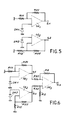
- the outputs of the circuit can also be symmetrical (figure 5) with an output Sl (high point) and an output S2 (low point).
- the output circuit then comprising a double amplifier 14/1, 14/2 connected to the receiving diodes DR1, DR2 with adjustment resistors R11, R21 and R12 and R22.
- the output can be asymmetrical (figure 6) if a third amplifier 14/3 of output S3 is added, provided with two inputs connected to the outputs S1, S2.
Landscapes
- Physics & Mathematics (AREA)
- Electromagnetism (AREA)
- Engineering & Computer Science (AREA)
- Computer Networks & Wireless Communication (AREA)
- Signal Processing (AREA)
- Amplifiers (AREA)
- Networks Using Active Elements (AREA)
Applications Claiming Priority (2)
| Application Number | Priority Date | Filing Date | Title |
|---|---|---|---|
| FR8314920 | 1983-09-20 | ||
| FR8314920A FR2552284B1 (fr) | 1983-09-20 | 1983-09-20 | Circuit isolateur a coupleur optoelectronique |
Publications (3)
| Publication Number | Publication Date |
|---|---|
| EP0136228A2 true EP0136228A2 (de) | 1985-04-03 |
| EP0136228A3 EP0136228A3 (de) | 1985-06-26 |
| EP0136228B1 EP0136228B1 (de) | 1988-01-07 |
Family
ID=9292358
Family Applications (1)
| Application Number | Title | Priority Date | Filing Date |
|---|---|---|---|
| EP84401817A Expired EP0136228B1 (de) | 1983-09-20 | 1984-09-13 | Isolierschaltung mit optoelektronischem Koppler |
Country Status (6)
| Country | Link |
|---|---|
| US (1) | US4638167A (de) |
| EP (1) | EP0136228B1 (de) |
| JP (1) | JPS6087514A (de) |
| CA (1) | CA1217244A (de) |
| DE (1) | DE3468599D1 (de) |
| FR (1) | FR2552284B1 (de) |
Cited By (1)
| Publication number | Priority date | Publication date | Assignee | Title |
|---|---|---|---|---|
| EP1835079A1 (de) * | 2006-03-17 | 2007-09-19 | Qinghua He | Elektromechanisch gesteuerter Bagger und Verfahren zur Steuerung des elektromechanisch gesteuerten Baggers. |
Families Citing this family (6)
| Publication number | Priority date | Publication date | Assignee | Title |
|---|---|---|---|---|
| US5146357A (en) * | 1990-05-04 | 1992-09-08 | Buffton Corporation | Data communications system that prevents undesired coupling between data stations |
| US5555438A (en) * | 1991-07-24 | 1996-09-10 | Allen-Bradley Company, Inc. | Method for synchronously transferring serial data to and from an input/output (I/O) module with true and complement error detection coding |
| US5245654A (en) * | 1991-10-10 | 1993-09-14 | Cermetek Microelectronics, Inc. | Solid state isolation device using opto-isolators |
| US5579144A (en) * | 1995-06-30 | 1996-11-26 | Siemens Components, Inc. | Data access arrangement having improved transmit-receive separation |
| JP3719413B2 (ja) | 2001-12-05 | 2005-11-24 | 日本電気株式会社 | データ伝送システム及びそれに用いられるデータ送受信装置と、その方法 |
| CN105245289A (zh) * | 2015-09-30 | 2016-01-13 | 宁波环球广电科技有限公司 | 无电源供电光接收机 |
Family Cites Families (6)
| Publication number | Priority date | Publication date | Assignee | Title |
|---|---|---|---|---|
| US3333208A (en) * | 1963-10-09 | 1967-07-25 | Gen Electric | Automatic gain control amplifier |
| US3430054A (en) * | 1965-01-15 | 1969-02-25 | Siemens Ag | Apparatus for modulating direct voltages and currents |
| DE2143792B2 (de) * | 1971-09-01 | 1973-09-20 | Siemens Ag, 1000 Berlin U. 8000 Muenchen | Optoelektronischer Signalubertrager |
| JPS49102261A (de) * | 1973-01-31 | 1974-09-27 | ||
| US4054834A (en) * | 1976-01-14 | 1977-10-18 | Compagnie Generale D'electricite S.A. | Device for measuring AC in a high tension line |
| US4386371A (en) * | 1981-07-28 | 1983-05-31 | Rca Corporation | Wired remote control apparatus for a television receiver |
-
1983
- 1983-09-20 FR FR8314920A patent/FR2552284B1/fr not_active Expired
-
1984
- 1984-09-13 EP EP84401817A patent/EP0136228B1/de not_active Expired
- 1984-09-13 DE DE8484401817T patent/DE3468599D1/de not_active Expired
- 1984-09-18 JP JP59195630A patent/JPS6087514A/ja active Pending
- 1984-09-19 CA CA000463598A patent/CA1217244A/en not_active Expired
- 1984-09-19 US US06/652,306 patent/US4638167A/en not_active Expired - Fee Related
Non-Patent Citations (1)
| Title |
|---|
| ELECTRONIC ENGINEERING, vol. 46, no. 556, juin 1974, pages 46-48, Londres, GB; P. TURNER: "Faster optically-coupled isolator is compatible with t.t.l. interfaces" * |
Cited By (1)
| Publication number | Priority date | Publication date | Assignee | Title |
|---|---|---|---|---|
| EP1835079A1 (de) * | 2006-03-17 | 2007-09-19 | Qinghua He | Elektromechanisch gesteuerter Bagger und Verfahren zur Steuerung des elektromechanisch gesteuerten Baggers. |
Also Published As
| Publication number | Publication date |
|---|---|
| US4638167A (en) | 1987-01-20 |
| EP0136228B1 (de) | 1988-01-07 |
| JPS6087514A (ja) | 1985-05-17 |
| DE3468599D1 (en) | 1988-02-11 |
| CA1217244A (en) | 1987-01-27 |
| EP0136228A3 (de) | 1985-06-26 |
| FR2552284A1 (fr) | 1985-03-22 |
| FR2552284B1 (fr) | 1985-10-25 |
Similar Documents
| Publication | Publication Date | Title |
|---|---|---|
| EP0136228B1 (de) | Isolierschaltung mit optoelektronischem Koppler | |
| FR2485295A1 (fr) | Circuit de commande d'impedance par reaction | |
| EP0130260B1 (de) | Schnittstellenmodul für Fernsprechleitungen | |
| FR2638913A1 (fr) | Procede et circuit pour produire une tension de reference | |
| EP0194177A1 (de) | Teilnehmerschnittstellenschaltung mit Überwachungsbetrieb bei verringerter Speisung | |
| EP0052040A1 (de) | CMOS-integrierter AB-Verstärker | |
| FR2623951A1 (fr) | Amplificateur lineaire hyperfrequence a tres large bande passante | |
| FR2677512A1 (fr) | Circuit amplificateur large bande a controle automatique de gain et de tension de decalage. | |
| FR2527399A1 (fr) | Circuit a impedance d'entree, elevee | |
| EP0199332B1 (de) | Empfänger für optische Breitbandsignale | |
| EP3691122A1 (de) | Audio-verstärker klasse ad | |
| BE549967A (de) | ||
| FR2488087A1 (fr) | Circuit de telealimentation pour liaison bifilaire analogique | |
| EP0120756A1 (de) | Hochfrequenzbandpassverstärker mit einem eine anpassbare Impedanz enthaltenden Oszillator | |
| EP0533230A1 (de) | Differenzverstärker, Oszillator und Mischer | |
| EP0699359B1 (de) | Vorspannungsstromgesteuerte elektronische schaltung, insbesondere einstellbarer widerstand, negativer widerstand, oder filter oder dergleichen | |
| EP0961422B1 (de) | Optischer Sender mit mehreren optischen Quellen | |
| FR2532492A1 (fr) | Circuit amplificateur audio | |
| WO2003009466A1 (fr) | Circuit de preamplification | |
| FR2621753A1 (fr) | Dispositif de commande automatique de gain et recepteur comportant un tel dispositif | |
| EP0986170A1 (de) | Schnittstelle zwischen einem breitbandigen optoelektronischen Sensor für Hyperfrequenzen und einer Last | |
| EP0083529A2 (de) | Verstärkereinrichtung für stark schwankende Spannungen und Spannungsquelle mit einer derartigen Verstärkereinrichtung | |
| EP0052347B1 (de) | Vorverstärker mit Trägerstrom, Schalter zum Unterbrechen des Mikrophons und eine Vorrichtung zum Signalisieren dieser Unterbrechung enthaltender Fernsprechapparat | |
| EP0954094B1 (de) | Verstärkerausgangsstufe mit Begrenzer für parasitäre Ströme | |
| EP0130261A1 (de) | Gleichstromspeiseschaltung für eine Leitungsschnittstellenschaltung |
Legal Events
| Date | Code | Title | Description |
|---|---|---|---|
| PUAI | Public reference made under article 153(3) epc to a published international application that has entered the european phase |
Free format text: ORIGINAL CODE: 0009012 |
|
| AK | Designated contracting states |
Designated state(s): BE CH DE GB IT LI NL SE |
|
| PUAL | Search report despatched |
Free format text: ORIGINAL CODE: 0009013 |
|
| AK | Designated contracting states |
Designated state(s): BE CH DE GB IT LI NL SE |
|
| RTI1 | Title (correction) | ||
| 17P | Request for examination filed |
Effective date: 19851129 |
|
| 17Q | First examination report despatched |
Effective date: 19870218 |
|
| GRAA | (expected) grant |
Free format text: ORIGINAL CODE: 0009210 |
|
| AK | Designated contracting states |
Kind code of ref document: B1 Designated state(s): BE CH DE GB IT LI NL SE |
|
| REF | Corresponds to: |
Ref document number: 3468599 Country of ref document: DE Date of ref document: 19880211 |
|
| ITF | It: translation for a ep patent filed | ||
| GBT | Gb: translation of ep patent filed (gb section 77(6)(a)/1977) | ||
| PLBE | No opposition filed within time limit |
Free format text: ORIGINAL CODE: 0009261 |
|
| STAA | Information on the status of an ep patent application or granted ep patent |
Free format text: STATUS: NO OPPOSITION FILED WITHIN TIME LIMIT |
|
| 26N | No opposition filed | ||
| PGFP | Annual fee paid to national office [announced via postgrant information from national office to epo] |
Ref country code: SE Payment date: 19910813 Year of fee payment: 8 |
|
| PGFP | Annual fee paid to national office [announced via postgrant information from national office to epo] |
Ref country code: GB Payment date: 19910827 Year of fee payment: 8 |
|
| PGFP | Annual fee paid to national office [announced via postgrant information from national office to epo] |
Ref country code: DE Payment date: 19910831 Year of fee payment: 8 |
|
| PGFP | Annual fee paid to national office [announced via postgrant information from national office to epo] |
Ref country code: CH Payment date: 19910902 Year of fee payment: 8 |
|
| PGFP | Annual fee paid to national office [announced via postgrant information from national office to epo] |
Ref country code: BE Payment date: 19910911 Year of fee payment: 8 |
|
| ITTA | It: last paid annual fee | ||
| PGFP | Annual fee paid to national office [announced via postgrant information from national office to epo] |
Ref country code: NL Payment date: 19910930 Year of fee payment: 8 |
|
| PG25 | Lapsed in a contracting state [announced via postgrant information from national office to epo] |
Ref country code: GB Effective date: 19920913 |
|
| PG25 | Lapsed in a contracting state [announced via postgrant information from national office to epo] |
Ref country code: SE Effective date: 19920914 |
|
| PG25 | Lapsed in a contracting state [announced via postgrant information from national office to epo] |
Ref country code: LI Effective date: 19920930 Ref country code: CH Effective date: 19920930 Ref country code: BE Effective date: 19920930 |
|
| BERE | Be: lapsed |
Owner name: TELEDIFFUSION DE FRANCE Effective date: 19920930 Owner name: LESEURE JEAN-YVES Effective date: 19920930 |
|
| PG25 | Lapsed in a contracting state [announced via postgrant information from national office to epo] |
Ref country code: NL Effective date: 19930401 |
|
| GBPC | Gb: european patent ceased through non-payment of renewal fee |
Effective date: 19920913 |
|
| NLV4 | Nl: lapsed or anulled due to non-payment of the annual fee | ||
| REG | Reference to a national code |
Ref country code: CH Ref legal event code: PL |
|
| PG25 | Lapsed in a contracting state [announced via postgrant information from national office to epo] |
Ref country code: DE Effective date: 19930602 |
|
| EUG | Se: european patent has lapsed |
Ref document number: 84401817.6 Effective date: 19930406 |