EP0136235A2 - Canon perforateur destiné à être descendu au travers d'un tubage de production de puits - Google Patents
Canon perforateur destiné à être descendu au travers d'un tubage de production de puits Download PDFInfo
- Publication number
- EP0136235A2 EP0136235A2 EP84401860A EP84401860A EP0136235A2 EP 0136235 A2 EP0136235 A2 EP 0136235A2 EP 84401860 A EP84401860 A EP 84401860A EP 84401860 A EP84401860 A EP 84401860A EP 0136235 A2 EP0136235 A2 EP 0136235A2
- Authority
- EP
- European Patent Office
- Prior art keywords
- carrier
- charges
- focused
- perforating gun
- charge
- Prior art date
- Legal status (The legal status is an assumption and is not a legal conclusion. Google has not performed a legal analysis and makes no representation as to the accuracy of the status listed.)
- Granted
Links
Images
Classifications
-
- E—FIXED CONSTRUCTIONS
- E21—EARTH OR ROCK DRILLING; MINING
- E21B—EARTH OR ROCK DRILLING; OBTAINING OIL, GAS, WATER, SOLUBLE OR MELTABLE MATERIALS OR A SLURRY OF MINERALS FROM WELLS
- E21B43/00—Methods or apparatus for obtaining oil, gas, water, soluble or meltable materials or a slurry of minerals from wells
- E21B43/11—Perforators; Permeators
- E21B43/116—Gun or shaped-charge perforators
- E21B43/117—Shaped-charge perforators
Definitions
- the present invention relates to perforating guns and particularly to a perforating gun assembly that is designed to be run through the tubing string of a well.
- the assembly is designed for use in deep wells with high temperatures and high pressures. Temperatures would normally be in excess of 340°F.
- the system of using charges suspended on a carrier is satisfactory in wells that have temperatures below approximately 300°F, but cannot generally be used in wells above 30°F, due to the temperature effect on the primacord and detonator used in the perforating gun.
- a retrievable gun is used, but the hollow carrier is designed with sufficient strength and wall thickness to limit swelling beyond a pre-determined amount. This allows the gun carrier to be retrieved.
- the size of the carrier of this system limits the charge size and potential perforation penetration (effectiveness).
- One embodiment of the present invention is directed to the solution of the above problems by providing a perforating gun assembly in which larger perforating charges are loaded in a amaller steel tube.
- the outer diameter of the tube is selected so that the complete assembly may be lowered through normal production tubing, i.e., 2-7/8 inch outside diameter tubing and associated downhole tubular accessories and packer (tubing-casing annulus seal).
- the charges are suspended on a loading strip that also provides support for the primao d rd for igniting the charges as well as the wire line used for igniting the primacord.
- the charges in the gun are as large as those used in carriers which would be limited by clearance in deep well designs.
- This embodiment combines the advantage of the expendable gun, namely, a larger perforating charge, with the temperature and mechanical protection provided by a carrier, a carrier which is normally retrievable but has a clearance limitation when loaded with the desired perforating charge.
- the loading strip is supported from the upper and/or head of the assembly by means of plastic screws, for example, nylon screws which can be easily fractured when the charges are fired.
- the steel tube is attached to the head member by means of frangible pins which also fracture upon the firing of the charges. O-rings, or similar sealing devices are used to provide a fluid-tight seal between the steel tube and the head member, as well as between the tube and the bottom closure of the tube.
- the perforating charges are aligned in the tube so that they face one direction while one or more non-focused charges are loaded in the top of the tube.
- the non-focused charges are directed in the opposite direction from the perforating charges and are used to separate the tube from the head member.
- the complete assembly is lowered through the tubing string into the portion of the well below the tubing string. Since wells normally will have sane inclination the assembly is designed to seek the low side of the casing. The assembly is also designed so that when it seeks the low side, the perforating charges will be directed toward this side of the casing while the non-focused charges will be directed in the opposite direction. This ensures that the non-focused charges will not perforate or otherwise damage the casing.
- the perforating charges will fire first and perforate the casing.
- the non-focused charges will fire last and separate the tube from the head so that it can fall to the bottom of the hole.
- One aspect of the present invention is directed to a through the tubing perforating gun assembly characterized by: a uniform non-frangible tubular charge carrier; an upper head member, said head member being attached to said carrier by a first frangible means; a plurality of focused perforating charges, said charges being disposed on a loading strip, said charges being disposed in said carrier and said loading strip being secured to said head member by a second frangible means; at least one non-focused charge disposed at the top of said loading strip for opening a hole in the tubular charge carrier to allow an inrush of well fluids for fracturing both said frangible means and separating said carrier and said loading strip from said upper head member; and a lower end cap disposed to close the lower end of said carrier.
- Another aspect of the present invention is directed to a method for perforating a well bore casing characterized by the steps of: lowering into the well bore casing a perforating gun assembly comprising a plurality of focused perforating charges and at least one non-focused charge attached on a loading strip disposed within a non-frangible carrier, the at least one non-focused charge attached at the top of said loading strip, and said loading strip and carrier fastened to an upper head member with frangible means; detonating said focused charges to perforate said well bore casing; and, detonating said at least one non-focused charge to rupture said charge carrier thereby affording the inrush of well fluids for fracturing said frangible means and separating said carrier and said loading strip from said upper head member.
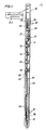
- the assembly utilizes an upper or head member 10 to which the tubular member 11 is attached and a lower end cap 12.
- the tubular member 11 is made of steel and is designed to withstand bore hole pressures without deforming.
- the tube diameter of that tubular member 11 is chosen so that it can be easily be lowered through the well production tubing. For example, a 1.835 inch O.D. tube having a 0.136 inch wall may be easily be lowered through a 2-7/8 inch O.D. dianeter production string with typical I.D. from 2.441 inch to 1.995 inch.
- the tube can be formed of any suitable material, for example, a AISI 4lxx series steel that is hardened to a Rockwell hardness (R c ) of 33 or greater.
- Perforating charges 13, 14, 15 and 16 are positioned in the tube and attached to the loading strip 17.
- the perforating charges are preferably 6.5 gran charges used in a 2 inch perforating gun.
- the primaoord 20 which is used to fire the charges and the wire conductor 22 used to detonate the firing cap 23 located in the bottom of the tubular member 11 which is sealed by the end cap.
- the conductor 22 forms part of the wire line which is attached to the head member 10 by conventional means and used for lowering the perforating gun assembly into the well. It should be noted that all the perforating charges 13-16 are directed in a single direction, i.e., to the right, as shown in Figure 1.
- the charges 30 and 31 are used to separate the tubular member 11 and the end cap 12 and the remaining portions of the system fran the head member 10.
- the charges 30 and 31 are preferably 13 gram non-focused charges. Since the primacord 20 connects to all the charges in series, the charges 30 and 31 will be fired after the perforating charges are fired and not interfere with the perforation of the well casing.
- the head member 10 is attached or secured to the tubular member 11 by means of two frangible pins 34.
- the pins are designed so that they can be readily fractured by the fluid inrush resulting from the firing of the charges 30 and 31, yet have sufficient mechanical strength to support the tubular member 11 and the perforating charges and the remainder of the equipment, as it is lowered into the well.
- spiral type roll pins may be used.
- a pair of O-rings 35 are provided for ensuring a fluid-tight seal between the tubular member 11 and the head member 10.
- the loading strip 17 is attached to the head member by a frangible fastener 33 that may comprise a plastic fastening member such as a nylon cap screw that is easily fractured by the firing of the charges 30 and 31.
- the bottom of the tubular member is closed ty the end cap 12 which is secured to the tubular member by suitable cap screws 36.
- a pair of O-rings 37 are provided for assuring a fluid-tight seal between the end cap and the tubular member.
- the lower portion of the tubular member is provided with a filler member 40 which has a central opening 41 through which the primacord and the wire may pass.
- the filler member may be formed of aluminum or similar material and is designed to prevent collapsing or deforming of the lower portion of the tubular member 11. It is necessary to ensure that the tubular member 11 remains substantially straight, so that after separating from the head member 10 it can freely fall to the bottom of the well and not interfere with production from the well.
- the assembly is also provided with an orienting means 50, for example, a magnetic positioning device as a means for orienting it with the low side cf the well casing.
- a magnet located above the head member 10 can be used to roll the tubular member 11 to such a position that the perforating charges 13-16 are directed toward the low side of the casing.
- This type of orienting equipment is known and in commercial use, for example, the equipment manufactured by Schlumberger Well Services, Houston, Texas. Other known methods of orienting such as a mechanical sidekicker or sidekicker-magnet combination could be used.
- tubular member 11 After the tubular member 11 is oriented with the low side of the well, it is held to the well casing by magnetic means.
- the gun assembly After the gun assembly has been completely assembled using the frangible pins 34 and the plastic fastening means 33, it can be run in the well. As is explained the 1.835 inch O.D. tubing will pass through 2-7/8 inch production tubing. As the gun exits from the bottom cf the production tubing, it will orient itself with the low side of the well casing and attach to the casing by the magnetic means. In orienting itself towards the low side, the perforating charge 13-16 will be directed toward the low side cf the casing while the non-focused fracturing charges 30-31 will be directed in the opposite direction. After the gun is fired, the primacord will detonate the perforating charges in an ascending order and finally detonate the two fracturing charges 30 and 31.
- the detonation of the fracturing charges 30 and 31 will open two one inch holes in the tubular member at the top. This will allow an inrush of well fluids and separate the tubular member from the head member by fracturing the two spiral pins and plastic screw holding the carrier strip. The tubular menber will fall to the bottom of the well and not interfere with production from the well. It is important that the fastening means 33 and 34 be easily fractured by the firing of the charges 30 and 31 and the resulting inrush of well fluids and that the filler member 40 be placed at the bottom of the tube, so that the tube is not distorted or bent in a manner that would prevent its falling to the bottom of the well.
- the fracturing charges 30 and 31 will not interfere with the normal operation of the perforating charges, nor will they damage the well casing, since they are directed in the opposite direction from the perforating charges.
- the present inventive apparatus may include means for selectively detonating the focused charges and the non-focused charges, respectively, so that the carrier may be detached from the upper head member only when necessary.
- filler member 40 may not be necessary. Accordingly, the invention is to be limited only by the scope of the appended claims.
Landscapes
- Life Sciences & Earth Sciences (AREA)
- Engineering & Computer Science (AREA)
- Geology (AREA)
- Mining & Mineral Resources (AREA)
- Physics & Mathematics (AREA)
- Environmental & Geological Engineering (AREA)
- Fluid Mechanics (AREA)
- General Life Sciences & Earth Sciences (AREA)
- Geochemistry & Mineralogy (AREA)
- Perforating, Stamping-Out Or Severing By Means Other Than Cutting (AREA)
Applications Claiming Priority (2)
| Application Number | Priority Date | Filing Date | Title |
|---|---|---|---|
| US534014 | 1983-09-20 | ||
| US06/534,014 US4496009A (en) | 1983-09-20 | 1983-09-20 | Through the tubing perforating gun assembly |
Publications (3)
| Publication Number | Publication Date |
|---|---|
| EP0136235A2 true EP0136235A2 (fr) | 1985-04-03 |
| EP0136235A3 EP0136235A3 (en) | 1985-09-25 |
| EP0136235B1 EP0136235B1 (fr) | 1988-09-21 |
Family
ID=24128355
Family Applications (1)
| Application Number | Title | Priority Date | Filing Date |
|---|---|---|---|
| EP84401860A Expired EP0136235B1 (fr) | 1983-09-20 | 1984-09-20 | Canon perforateur destiné à être descendu au travers d'un tubage de production de puits |
Country Status (4)
| Country | Link |
|---|---|
| US (1) | US4496009A (fr) |
| EP (1) | EP0136235B1 (fr) |
| DE (1) | DE3474188D1 (fr) |
| OA (1) | OA07819A (fr) |
Families Citing this family (11)
| Publication number | Priority date | Publication date | Assignee | Title |
|---|---|---|---|---|
| US5007344A (en) * | 1988-12-01 | 1991-04-16 | Dresser Industries, Inc. | Dual firing system for a perforating gun |
| US5107929A (en) * | 1990-08-09 | 1992-04-28 | Schlumberger Technology Corporation | Drop off method for perforating gun capsule charge carriers |
| US5063822A (en) * | 1990-08-09 | 1991-11-12 | Schlumberger Technology Corporation | Perforating gun assembly including a carrier having a first section adapted to separate from a second section when a charge on the second section detonates |
| US6523449B2 (en) * | 2001-01-11 | 2003-02-25 | Schlumberger Technology Corporation | Perforating gun |
| US6702039B2 (en) | 2001-03-30 | 2004-03-09 | Schlumberger Technology Corporation | Perforating gun carriers and their methods of manufacture |
| US20030000411A1 (en) * | 2001-06-29 | 2003-01-02 | Cernocky Edward Paul | Method and apparatus for detonating an explosive charge |
| US6962202B2 (en) * | 2003-01-09 | 2005-11-08 | Shell Oil Company | Casing conveyed well perforating apparatus and method |
| CN100491692C (zh) * | 2005-09-15 | 2009-05-27 | 广意协力石油技术开发(北京)有限公司 | 无枪身复合射孔装置 |
| US7409992B2 (en) * | 2006-01-11 | 2008-08-12 | Schlumberger Technology Corporation | Perforating gun |
| US8327746B2 (en) * | 2009-04-22 | 2012-12-11 | Schlumberger Technology Corporation | Wellbore perforating devices |
| BR112017014190A2 (pt) | 2015-02-13 | 2018-03-06 | Halliburton Energy Services Inc | métodos para gerenciar uma condição de desequilíbrio a menor dinâmico resultante do disparo de um canhão em uma localização de furo abaixo e para fornecer um conjunto de canhão para uso durante uma operação de canhoneio em um furo de poço, e, conjunto de controle de pressão de furo de poço para uso durante uma operação de canhoneio em um furo de poço. |
Family Cites Families (12)
| Publication number | Priority date | Publication date | Assignee | Title |
|---|---|---|---|---|
| US25407A (en) * | 1859-09-13 | Exhaust-pipe fob | ||
| USRE25407E (en) | 1963-06-25 | Method and apparatus for detonating | ||
| US2965031A (en) * | 1957-10-11 | 1960-12-20 | Seismograph Service Corp | Well bore detector and perforating apparatus |
| US3110257A (en) * | 1958-03-05 | 1963-11-12 | Schlumberger Well Surv Corp | Well perforating method and apparatus |
| US2965176A (en) * | 1958-03-05 | 1960-12-20 | Schlumberger Well Surv Corp | Formation testers |
| US3305032A (en) * | 1964-06-11 | 1967-02-21 | Schlumberger Technology Corp | Well completion apparatus |
| US3366188A (en) * | 1965-06-28 | 1968-01-30 | Dresser Ind | Burr-free shaped charge perforating |
| US4194577A (en) * | 1977-10-17 | 1980-03-25 | Peabody Vann | Method and apparatus for completing a slanted wellbore |
| US4291623A (en) * | 1978-12-29 | 1981-09-29 | Nl Industries, Inc. | Binary electroexplosive device and method of assembly thereof |
| US4253523A (en) * | 1979-03-26 | 1981-03-03 | Ibsen Barrie G | Method and apparatus for well perforation and fracturing operations |
| US4326462A (en) * | 1979-09-21 | 1982-04-27 | Schlumberger Technology Corporation | Shaped charge retention and barrier clip |
| US4312273A (en) * | 1980-04-07 | 1982-01-26 | Shaped Charge Specialist, Inc. | Shaped charge mounting system |
-
1983
- 1983-09-20 US US06/534,014 patent/US4496009A/en not_active Expired - Lifetime
-
1984
- 1984-09-20 OA OA58395A patent/OA07819A/xx unknown
- 1984-09-20 EP EP84401860A patent/EP0136235B1/fr not_active Expired
- 1984-09-20 DE DE8484401860T patent/DE3474188D1/de not_active Expired
Also Published As
| Publication number | Publication date |
|---|---|
| OA07819A (en) | 1986-11-20 |
| DE3474188D1 (en) | 1988-10-27 |
| US4496009A (en) | 1985-01-29 |
| EP0136235B1 (fr) | 1988-09-21 |
| EP0136235A3 (en) | 1985-09-25 |
Similar Documents
| Publication | Publication Date | Title |
|---|---|---|
| US6173779B1 (en) | Collapsible well perforating apparatus | |
| US7621342B2 (en) | Method for retaining debris in a perforating apparatus | |
| EP3359906B1 (fr) | Perforateur de champ pétrolifère conçu pour l'enlèvement de cuvelage à grand volume | |
| US6497284B2 (en) | Single trip perforating and fracturing/gravel packing | |
| EP3108097B1 (fr) | Système de liaison monobloc en zinc | |
| US8807206B2 (en) | Perforating gun debris retention assembly and method of use | |
| US8127846B2 (en) | Wiper plug perforating system | |
| CA2466223C (fr) | Methode d'enlevement d'un outil d'un puits | |
| US5845712A (en) | Apparatus and associated methods for gravel packing a subterranean well | |
| US6675896B2 (en) | Detonation transfer subassembly and method for use of same | |
| US6494261B1 (en) | Apparatus and methods for perforating a subterranean formation | |
| US5165478A (en) | Downhole activated process and apparatus for providing cathodic protection for a pipe in a wellbore | |
| US20080066912A1 (en) | Method and Apparatus for Perforating and Isolating Perforations in a Wellbore | |
| US10851624B2 (en) | Perforating gun assembly and methods of use | |
| WO1993006333A1 (fr) | Procede et appareil actionnes au fond d'un puits, destines a centrer un tubage dans un puits de forage | |
| EP2231990A2 (fr) | Dispositif et procédé de réduction de la pression de rupture/d'amorce de fracture | |
| US6220370B1 (en) | Circulating gun system | |
| US11002119B2 (en) | Energetic perforator fill and delay method | |
| US4496009A (en) | Through the tubing perforating gun assembly | |
| US4538680A (en) | Gun below packer completion tool string | |
| CA1196570A (fr) | Methode de controle d'une eruption souterraine | |
| US10337299B2 (en) | Perforating apparatus and method having internal load path | |
| US20030047313A1 (en) | Drillable core perforating gun and method of utilizing the same | |
| WO1995009965A1 (fr) | Dispositifs a orifices d'ecoulement transportes par tubage et destines a des trous de forage | |
| RU96110255A (ru) | Способ вскрытия продуктивного пласта в обсаженной скважине |
Legal Events
| Date | Code | Title | Description |
|---|---|---|---|
| PUAI | Public reference made under article 153(3) epc to a published international application that has entered the european phase |
Free format text: ORIGINAL CODE: 0009012 |
|
| AK | Designated contracting states |
Designated state(s): DE FR GB IT NL |
|
| PUAL | Search report despatched |
Free format text: ORIGINAL CODE: 0009013 |
|
| AK | Designated contracting states |
Designated state(s): DE FR GB IT NL |
|
| 17P | Request for examination filed |
Effective date: 19860313 |
|
| 17Q | First examination report despatched |
Effective date: 19861128 |
|
| D17Q | First examination report despatched (deleted) | ||
| GRAA | (expected) grant |
Free format text: ORIGINAL CODE: 0009210 |
|
| AK | Designated contracting states |
Kind code of ref document: B1 Designated state(s): DE FR GB IT NL |
|
| PG25 | Lapsed in a contracting state [announced via postgrant information from national office to epo] |
Ref country code: IT Free format text: LAPSE BECAUSE OF FAILURE TO SUBMIT A TRANSLATION OF THE DESCRIPTION OR TO PAY THE FEE WITHIN THE PRESCRIBED TIME-LIMIT;WARNING: LAPSES OF ITALIAN PATENTS WITH EFFECTIVE DATE BEFORE 2007 MAY HAVE OCCURRED AT ANY TIME BEFORE 2007. THE CORRECT EFFECTIVE DATE MAY BE DIFFERENT FROM THE ONE RECORDED. Effective date: 19880921 |
|
| REF | Corresponds to: |
Ref document number: 3474188 Country of ref document: DE Date of ref document: 19881027 |
|
| ET | Fr: translation filed | ||
| PLBE | No opposition filed within time limit |
Free format text: ORIGINAL CODE: 0009261 |
|
| STAA | Information on the status of an ep patent application or granted ep patent |
Free format text: STATUS: NO OPPOSITION FILED WITHIN TIME LIMIT |
|
| 26N | No opposition filed | ||
| PG25 | Lapsed in a contracting state [announced via postgrant information from national office to epo] |
Ref country code: DE Effective date: 19900601 |
|
| PGFP | Annual fee paid to national office [announced via postgrant information from national office to epo] |
Ref country code: NL Payment date: 19910930 Year of fee payment: 8 |
|
| PG25 | Lapsed in a contracting state [announced via postgrant information from national office to epo] |
Ref country code: NL Effective date: 19930401 |
|
| NLV4 | Nl: lapsed or anulled due to non-payment of the annual fee | ||
| PGFP | Annual fee paid to national office [announced via postgrant information from national office to epo] |
Ref country code: FR Payment date: 19960711 Year of fee payment: 13 |
|
| PG25 | Lapsed in a contracting state [announced via postgrant information from national office to epo] |
Ref country code: FR Free format text: THE PATENT HAS BEEN ANNULLED BY A DECISION OF A NATIONAL AUTHORITY Effective date: 19970930 |
|
| REG | Reference to a national code |
Ref country code: FR Ref legal event code: ST |
|
| REG | Reference to a national code |
Ref country code: GB Ref legal event code: IF02 |
|
| PGFP | Annual fee paid to national office [announced via postgrant information from national office to epo] |
Ref country code: GB Payment date: 20030917 Year of fee payment: 20 |
|
| PG25 | Lapsed in a contracting state [announced via postgrant information from national office to epo] |
Ref country code: GB Free format text: LAPSE BECAUSE OF EXPIRATION OF PROTECTION Effective date: 20040919 |
|
| REG | Reference to a national code |
Ref country code: GB Ref legal event code: PE20 |