EP0136252A2 - Elément de connection pour élément de construction lamellé - Google Patents
Elément de connection pour élément de construction lamellé Download PDFInfo
- Publication number
- EP0136252A2 EP0136252A2 EP84710024A EP84710024A EP0136252A2 EP 0136252 A2 EP0136252 A2 EP 0136252A2 EP 84710024 A EP84710024 A EP 84710024A EP 84710024 A EP84710024 A EP 84710024A EP 0136252 A2 EP0136252 A2 EP 0136252A2
- Authority
- EP
- European Patent Office
- Prior art keywords
- ventilation openings
- housing
- coupling element
- element according
- section
- Prior art date
- Legal status (The legal status is an assumption and is not a legal conclusion. Google has not performed a legal analysis and makes no representation as to the accuracy of the status listed.)
- Withdrawn
Links
- 238000009423 ventilation Methods 0.000 claims abstract description 40
- 230000008878 coupling Effects 0.000 claims abstract description 38
- 238000010168 coupling process Methods 0.000 claims abstract description 38
- 238000005859 coupling reaction Methods 0.000 claims abstract description 38
- 239000002131 composite material Substances 0.000 claims abstract description 27
- 239000010410 layer Substances 0.000 claims abstract description 16
- 239000006260 foam Substances 0.000 claims abstract description 12
- 239000012792 core layer Substances 0.000 claims abstract description 8
- 239000011541 reaction mixture Substances 0.000 claims abstract description 6
- 238000005187 foaming Methods 0.000 claims abstract description 5
- 238000013022 venting Methods 0.000 claims abstract description 3
- 239000004744 fabric Substances 0.000 claims description 10
- 239000004753 textile Substances 0.000 claims description 9
- 230000015572 biosynthetic process Effects 0.000 abstract description 2
- 238000004519 manufacturing process Methods 0.000 description 6
- 238000013459 approach Methods 0.000 description 2
- 238000001816 cooling Methods 0.000 description 2
- 238000010276 construction Methods 0.000 description 1
- 238000013461 design Methods 0.000 description 1
- 238000011161 development Methods 0.000 description 1
- 239000007788 liquid Substances 0.000 description 1
- 238000000034 method Methods 0.000 description 1
- 238000000465 moulding Methods 0.000 description 1
Images


Classifications
-
- E—FIXED CONSTRUCTIONS
- E04—BUILDING
- E04B—GENERAL BUILDING CONSTRUCTIONS; WALLS, e.g. PARTITIONS; ROOFS; FLOORS; CEILINGS; INSULATION OR OTHER PROTECTION OF BUILDINGS
- E04B1/00—Constructions in general; Structures which are not restricted either to walls, e.g. partitions, or floors or ceilings or roofs
- E04B1/38—Connections for building structures in general
- E04B1/61—Connections for building structures in general of slab-shaped building elements with each other
- E04B1/6108—Connections for building structures in general of slab-shaped building elements with each other the frontal surfaces of the slabs connected together
- E04B1/612—Connections for building structures in general of slab-shaped building elements with each other the frontal surfaces of the slabs connected together by means between frontal surfaces
- E04B1/6183—Connections for building structures in general of slab-shaped building elements with each other the frontal surfaces of the slabs connected together by means between frontal surfaces with rotatable locking means co-operating with a recess
-
- E—FIXED CONSTRUCTIONS
- E04—BUILDING
- E04C—STRUCTURAL ELEMENTS; BUILDING MATERIALS
- E04C2/00—Building elements of relatively thin form for the construction of parts of buildings, e.g. sheet materials, slabs, or panels
- E04C2/02—Building elements of relatively thin form for the construction of parts of buildings, e.g. sheet materials, slabs, or panels characterised by specified materials
- E04C2/26—Building elements of relatively thin form for the construction of parts of buildings, e.g. sheet materials, slabs, or panels characterised by specified materials composed of materials covered by two or more of groups E04C2/04, E04C2/08, E04C2/10 or of materials covered by one of these groups with a material not specified in one of the groups
- E04C2/284—Building elements of relatively thin form for the construction of parts of buildings, e.g. sheet materials, slabs, or panels characterised by specified materials composed of materials covered by two or more of groups E04C2/04, E04C2/08, E04C2/10 or of materials covered by one of these groups with a material not specified in one of the groups at least one of the materials being insulating
-
- E—FIXED CONSTRUCTIONS
- E04—BUILDING
- E04H—BUILDINGS OR LIKE STRUCTURES FOR PARTICULAR PURPOSES; SWIMMING OR SPLASH BATHS OR POOLS; MASTS; FENCING; TENTS OR CANOPIES, IN GENERAL
- E04H5/00—Buildings or groups of buildings for industrial or agricultural purposes
- E04H5/10—Buildings forming part of cooling plants
Definitions
- the invention relates to a coupling element for composite components with rigid cover layers and a core layer made of closed-cell rigid foam, which is produced by foaming a reaction mixture introduced between the cover layers with simultaneous venting of the cavity, a coupling half of each in the end faces or in the edge region of the side faces of the composite component
- Two-part hook couplings is arranged, each of which comprises a locking bolt or pivotable locking hook arranged in a housing.
- Coupling elements of the type described above for composite components are known. These composite components are assembled on site by means of the two-part hook couplings, for example to form cold rooms or cold stores, in that the composite components forming the floor, the side walls and the ceiling are connected to one another with the aid of the two-part hook couplings.
- the housing of the coupling halves which either contains a locking bolt or a pivotable locking hook, is for this purpose arranged at predetermined points in the end faces or in the edge areas of the side faces of the composite components.
- the known composite components are manufactured in a stable shape, in which the lower cover layer, then the housing of the hook couplings and finally the upper cover layer are inserted, the housings being plugged onto the side or cross bars of the mold that form the later end faces of the composite component form.
- the preferably liquid reaction mixture is introduced into the cavity, the volume of the reaction mixture being between 35 and 45% of the total volume of the core layer to be produced.
- the foam which expands under an overpressure of up to 2 bar, fills the entire cavity by displacing the air in the cavity of the mold and, during its subsequent curing, not only connects the rigid cover layers to one another, but also holds the molded-in coupling halves.
- Vent openings must be provided so that the air displaced during the foaming process can escape from the cavity of the mold. These are provided either in the cover layers or in the side and cross bars of the mold. The foam emerging from these ventilation openings must be removed after the composite component has been completed.
- the invention has for its object to provide a coupling element for composite components of the type described above, in the manufacture of which there is no need to provide special ventilation openings.
- the solution to this problem by the invention is characterized in that the housing of the hook couplings are provided with a plurality of ventilation openings.
- the formation of the ventilation openings required for the manufacturing process on the housings of the hook couplings eliminates the need to provide special ventilation openings or to use them as prefabricated moldings in the mold for producing the composite components. Since the housing of the hook couplings is evenly distributed over the circumference of the end faces, the proposal according to the invention results in a uniform and good ventilation of the cavity without special measures having to be taken for this.
- the ventilation openings are designed as channels with a small cross section and a length greater than the cross section, so that although air can escape almost unhindered, the escape of foam is prevented. This eliminates the need to rework the composite component by removing excess foam.
- the ventilation openings are formed between the interior of the housing and an outer surface of the housing facing the interior of the composite component. The ventilation is thus carried out via the interior of the clutch housing.
- the ventilation openings are formed within stopper-like projections which are formed on the rear of the housing.
- the ventilation openings are formed within chambers formed on the side of the housing.
- the cavity is not vented through the interior of the clutch housing, but through the chambers formed on the side of the clutch housing, so that even foam passing through the ventilation openings does not get into the interior of the clutch housing.
- the ventilation openings can be formed with a circular cross section or with a cross section in the form of a circular arc.
- This cross-sectional design enables a particularly simple production of the ventilation openings as channels with a small cross-section and a great length.
- the ventilation openings are covered by a textile fabric with openings of small cross-section.
- this textile fabric can be formed by a mat made of needle felt.
- the textile fabric is preferably arranged in a frame-like recess in the housing.
- the ventilation openings covered by the fabric can be formed by webs which are spaced apart and parallel to one another.
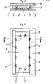
- FIG. 1 shows the construction of a cooling cell from composite components 1, which according to FIG. 3 consist of two rigid cover layers 2 and 3 and a core layer 4 of closed-cell rigid foam using an exemplary embodiment.
- Two-part hook couplings are arranged in the end faces or in the edge region of the side faces of the composite components 1, each of which comprises a locking bolt arranged in a housing 5 or a locking hook pivotable in a housing, as can be seen in the upper left part of FIG. 1.
- the composite components 1 are produced in a mold as shown in FIGS. 2 and 3.
- This mold comprises a mold base plate 6, on which a rigid cover layer 2 according to FIG. 3 is placed.
- the end faces of the composite component 1 are formed by molded side rails 7, which can best be seen in the top view of FIG. 2.
- the coupling housings 5, which are to be molded into the end faces of the composite component 1 in the exemplary embodiment shown in FIG. 2, are attached to these molded side rails 7.
- the second cover layer 3 is placed in the mold and the mold is closed by applying the mold cover plate 8.
- a reaction mixture is now introduced into the cavity of the mold via the filling tube 9 shown in FIG. 2 and forms the core layer by foaming. In this case, the air between the cover layers 2 and 3 in the mold must escape. This is done - as the arrows in FIG. 2 indicate - through the clutch housing 5.
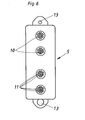
- plug-like projections 10 are formed on the rear of the housing 5, in each of which a plurality of ventilation openings 11 are provided.
- These vents 11 are designed as channels with a small cross section and a large length compared to their cross section, so that although the air can escape almost unhindered, leakage of the foam is prevented.
- the channel-shaped ventilation openings 11 have a circular cross section, which can be formed in a simple manner in the manufacture of the coupling housing 5 from plastic.
- the air emerging from the interior of the mold through the ventilation openings 11 enters the interior 12 of the clutch housing 5.
- the longitudinal section in FIG. 5 and the view in FIG. 6 also show that the coupling housing 5 is provided with fastening holes 13 for retaining screws to be screwed into the core layer 4.
- the vent openings 11 have a cross section in the form of a Kreisbo g enabschnit- tes, as shown in particular in FIG. 8.
- the ventilation openings 11 can be designed as channels with a small cross section and a large length compared to their cross section.
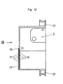
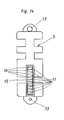
- FIGS. 12 to 14 shows a corresponding coupling element in which the ventilation openings 11 are formed within a frame 15.
- this frame 15 parallel and spaced apart webs 16 are formed, which form the ventilation openings 11 between them.
- the ventilation openings 11 are covered by a textile fabric 17, for example by a needle felt.
- This needle felt can be seen in cross section in FIG. 12 and in a top view in FIG. 13. The needle felt has been omitted in FIG. 14 in order to be able to represent the ventilation openings 11 and the webs 16.
Landscapes
- Engineering & Computer Science (AREA)
- Architecture (AREA)
- Civil Engineering (AREA)
- Structural Engineering (AREA)
- Physics & Mathematics (AREA)
- Electromagnetism (AREA)
- Connection Of Plates (AREA)
- Casting Or Compression Moulding Of Plastics Or The Like (AREA)
- Laminated Bodies (AREA)
Applications Claiming Priority (2)
| Application Number | Priority Date | Filing Date | Title |
|---|---|---|---|
| DE19833329814 DE3329814C1 (de) | 1983-08-18 | 1983-08-18 | Kupplungselement fuer Verbundbauteile |
| DE3329814 | 1983-08-18 |
Publications (2)
| Publication Number | Publication Date |
|---|---|
| EP0136252A2 true EP0136252A2 (fr) | 1985-04-03 |
| EP0136252A3 EP0136252A3 (fr) | 1985-05-29 |
Family
ID=6206845
Family Applications (1)
| Application Number | Title | Priority Date | Filing Date |
|---|---|---|---|
| EP84710024A Withdrawn EP0136252A3 (fr) | 1983-08-18 | 1984-08-07 | Elément de connection pour élément de construction lamellé |
Country Status (2)
| Country | Link |
|---|---|
| EP (1) | EP0136252A3 (fr) |
| DE (1) | DE3329814C1 (fr) |
Cited By (3)
| Publication number | Priority date | Publication date | Assignee | Title |
|---|---|---|---|---|
| WO2001002659A1 (fr) * | 1999-07-02 | 2001-01-11 | Jores Arkitektkontor | Systeme de construction |
| EP1449977A1 (fr) * | 2003-02-18 | 2004-08-25 | Ruredil S.p.A. | Dispositif de ventilation d'un élément de construction en béton armé avec des cavites ou éléments à réduction de poids |
| CN110629926A (zh) * | 2019-08-15 | 2019-12-31 | 李志珍 | 一种用于mri屏蔽室的高性能多功能一体板 |
Families Citing this family (4)
| Publication number | Priority date | Publication date | Assignee | Title |
|---|---|---|---|---|
| FR2589901B1 (fr) * | 1985-11-08 | 1990-04-06 | Dagard Fils Sa | Enceinte extensible a parois en panneaux assembles. |
| DE19713542A1 (de) * | 1997-04-02 | 1998-10-08 | Ilkazell Gmbh Zwickau Kaeltete | Selbsttragende Verbunddämmplatte und Verfahren zu ihrer Herstellung |
| DE102020116127A1 (de) * | 2020-06-18 | 2021-12-23 | Rahrbach Gmbh | Verriegelungsvorrichtung mit Entlüftungskanal |
| EP4050173B1 (fr) * | 2021-02-25 | 2023-01-18 | Steinbach & Vollmann GmbH | Connecteur de panneau à conduit d'air |
Family Cites Families (2)
| Publication number | Priority date | Publication date | Assignee | Title |
|---|---|---|---|---|
| US3365851A (en) * | 1965-02-05 | 1968-01-30 | Delron Company Inc | Panel structure and edging means gripping an embedded panel locking means |
| DE2063737A1 (en) * | 1970-12-24 | 1972-07-13 | Continental Gummi Werke Ag | Polyurethane foam moulded objects - without flaws in their closed pore surfaces |
-
1983
- 1983-08-18 DE DE19833329814 patent/DE3329814C1/de not_active Expired
-
1984
- 1984-08-07 EP EP84710024A patent/EP0136252A3/fr not_active Withdrawn
Cited By (3)
| Publication number | Priority date | Publication date | Assignee | Title |
|---|---|---|---|---|
| WO2001002659A1 (fr) * | 1999-07-02 | 2001-01-11 | Jores Arkitektkontor | Systeme de construction |
| EP1449977A1 (fr) * | 2003-02-18 | 2004-08-25 | Ruredil S.p.A. | Dispositif de ventilation d'un élément de construction en béton armé avec des cavites ou éléments à réduction de poids |
| CN110629926A (zh) * | 2019-08-15 | 2019-12-31 | 李志珍 | 一种用于mri屏蔽室的高性能多功能一体板 |
Also Published As
| Publication number | Publication date |
|---|---|
| DE3329814C1 (de) | 1984-10-11 |
| EP0136252A3 (fr) | 1985-05-29 |
Similar Documents
| Publication | Publication Date | Title |
|---|---|---|
| DE69911553T2 (de) | Geformtes schäumfähiges Material | |
| DE68922979T2 (de) | Thermoplastische Verbundwerkstoffplatte und daraus geformte Gegenstände. | |
| DE2937454C2 (de) | Verbundprofil, insbesondere für Fenster, Türen und Fassaden sowie Verfahren zum Herstellen des Verbundprofils | |
| DE602005000107T2 (de) | Verkleidungselement, insbesondere für einen Fahrzeuginnenraum, und Herstellungsverfahren hierfür | |
| DE2802237C2 (de) | Spritzgießform zum Herstellen von aus mindestens zwei verschiedenen Kunststoffmassen bestehenden und mindestens zwei unterschiedliche Bereiche aufweisenden Spritzgußteilen | |
| DE3413601A1 (de) | Verfahren und vorrichtung zur herstellung von verbundprofilen | |
| DE10141243A1 (de) | Innenschale für ein Dachmodul in Sandwich-Bauweise sowie Verfahren zu ihrer Herstellung | |
| DE2826729C2 (de) | Verfahren zum Herstellen von mehrschichtigen plattenförmigen Bauteilen | |
| DE112018004358T5 (de) | Dachgepäckträger für ein fahrzeug | |
| EP0136252A2 (fr) | Elément de connection pour élément de construction lamellé | |
| DE10257161A1 (de) | Instrumententafel sowie Verfahren zu deren Herstellung | |
| DE3204452A1 (de) | Verstaerkungen fuer kunststoffartikel | |
| DE2332778A1 (de) | Konstruktionselement | |
| DE4240431C2 (de) | Verfahren zur Verbesserung der Wärmedämmung an Rahmen aus wärmegedämmten Verbundprofilen | |
| CH665129A5 (de) | Verfahren zur herstellung eines skis und nach dem verfahren hergestellter ski. | |
| DE2047112A1 (de) | Halter für eine Tafel, insbesondere ein Nummernschild und Verfahren zur Herstellung desselben | |
| DE2724377A1 (de) | Profilstabaggregat | |
| DE1659705A1 (de) | Aus Kunststoffbauteilen zusammensetzbare wasserdichte Aussenfensterbank | |
| EP0906999A2 (fr) | Ame isolante de profilés composites de cadres de fenêtre ou de porte | |
| DE102019119479B4 (de) | Verfahren zur Herstellung eines Isolierpaneels | |
| DE3413113A1 (de) | Verfahren und vorrichtung zum herstellen eines wasserkastens fuer einen waermetauscher, insbesondere fuer ein kraftfahrzeug, durch formen und derart hergestellter wasserkasten | |
| DE19804222A1 (de) | Isoliersteg für Verbundprofile von Fenster- oder Türrahmen | |
| DE2844229A1 (de) | Rollenbahn | |
| DE1923878C3 (de) | Rolladenkasten | |
| DE19923480A1 (de) | Halbzeug aus Polymeren sowie Verfahren zu seiner Herstellung |
Legal Events
| Date | Code | Title | Description |
|---|---|---|---|
| PUAI | Public reference made under article 153(3) epc to a published international application that has entered the european phase |
Free format text: ORIGINAL CODE: 0009012 |
|
| PUAL | Search report despatched |
Free format text: ORIGINAL CODE: 0009013 |
|
| AK | Designated contracting states |
Designated state(s): AT BE CH FR GB IT LI LU NL SE |
|
| AK | Designated contracting states |
Designated state(s): AT BE CH FR GB IT LI LU NL SE |
|
| 17P | Request for examination filed |
Effective date: 19850926 |
|
| 17Q | First examination report despatched |
Effective date: 19860512 |
|
| STAA | Information on the status of an ep patent application or granted ep patent |
Free format text: STATUS: THE APPLICATION HAS BEEN WITHDRAWN |
|
| 18W | Application withdrawn |
Withdrawal date: 19860701 |
|
| RIN1 | Information on inventor provided before grant (corrected) |
Inventor name: DIE ERFINDER HABEN AUF IHRE NENNUNG VERZICHTET. |