EP0136253A1 - Dispositif moteur pour interrupteur à vide - Google Patents
Dispositif moteur pour interrupteur à vide Download PDFInfo
- Publication number
- EP0136253A1 EP0136253A1 EP84730080A EP84730080A EP0136253A1 EP 0136253 A1 EP0136253 A1 EP 0136253A1 EP 84730080 A EP84730080 A EP 84730080A EP 84730080 A EP84730080 A EP 84730080A EP 0136253 A1 EP0136253 A1 EP 0136253A1
- Authority
- EP
- European Patent Office
- Prior art keywords
- movable contact
- switching tube
- switching
- drive lever
- contact pin
- Prior art date
- Legal status (The legal status is an assumption and is not a legal conclusion. Google has not performed a legal analysis and makes no representation as to the accuracy of the status listed.)
- Granted
Links
- 230000005540 biological transmission Effects 0.000 claims abstract description 11
- 238000006073 displacement reaction Methods 0.000 description 4
- 230000000694 effects Effects 0.000 description 2
- 239000011810 insulating material Substances 0.000 description 2
- 230000004323 axial length Effects 0.000 description 1
- 230000006355 external stress Effects 0.000 description 1
- 238000010438 heat treatment Methods 0.000 description 1
- 238000012423 maintenance Methods 0.000 description 1
- 239000002184 metal Substances 0.000 description 1
- 230000000717 retained effect Effects 0.000 description 1
- 239000000344 soap Substances 0.000 description 1
- 125000006850 spacer group Chemical group 0.000 description 1
- 230000035882 stress Effects 0.000 description 1
Images


Classifications
-
- H—ELECTRICITY
- H01—ELECTRIC ELEMENTS
- H01H—ELECTRIC SWITCHES; RELAYS; SELECTORS; EMERGENCY PROTECTIVE DEVICES
- H01H33/00—High-tension or heavy-current switches with arc-extinguishing or arc-preventing means
- H01H33/60—Switches wherein the means for extinguishing or preventing the arc do not include separate means for obtaining or increasing flow of arc-extinguishing fluid
- H01H33/66—Vacuum switches
- H01H33/666—Operating arrangements
-
- H—ELECTRICITY
- H01—ELECTRIC ELEMENTS
- H01H—ELECTRIC SWITCHES; RELAYS; SELECTORS; EMERGENCY PROTECTIVE DEVICES
- H01H3/00—Mechanisms for operating contacts
- H01H3/32—Driving mechanisms, i.e. for transmitting driving force to the contacts
- H01H3/46—Driving mechanisms, i.e. for transmitting driving force to the contacts using rod or lever linkage, e.g. toggle
-
- Y—GENERAL TAGGING OF NEW TECHNOLOGICAL DEVELOPMENTS; GENERAL TAGGING OF CROSS-SECTIONAL TECHNOLOGIES SPANNING OVER SEVERAL SECTIONS OF THE IPC; TECHNICAL SUBJECTS COVERED BY FORMER USPC CROSS-REFERENCE ART COLLECTIONS [XRACs] AND DIGESTS
- Y10—TECHNICAL SUBJECTS COVERED BY FORMER USPC
- Y10T—TECHNICAL SUBJECTS COVERED BY FORMER US CLASSIFICATION
- Y10T403/00—Joints and connections
- Y10T403/32—Articulated members
- Y10T403/32114—Articulated members including static joint
- Y10T403/32196—Articulate joint is ball and socket
-
- Y—GENERAL TAGGING OF NEW TECHNOLOGICAL DEVELOPMENTS; GENERAL TAGGING OF CROSS-SECTIONAL TECHNOLOGIES SPANNING OVER SEVERAL SECTIONS OF THE IPC; TECHNICAL SUBJECTS COVERED BY FORMER USPC CROSS-REFERENCE ART COLLECTIONS [XRACs] AND DIGESTS
- Y10—TECHNICAL SUBJECTS COVERED BY FORMER USPC
- Y10T—TECHNICAL SUBJECTS COVERED BY FORMER US CLASSIFICATION
- Y10T403/00—Joints and connections
- Y10T403/32—Articulated members
- Y10T403/32606—Pivoted
- Y10T403/32631—Universal ball and socket
- Y10T403/32681—Composite ball
- Y10T403/32704—Stud extends into ball
Definitions
- the invention relates to a drive for a vacuum switch with between its movable contact pin and a actuating, fixedly mounted drive lever for transmitting the actuating force to a switching tube arranged joint parts which are provided with central bores for the passage of the movable contact pin of the switching tube and a spherical cap and one of these have adapted spherical joint socket, the spherical center of the calotte being offset from the center line of the drive lever, which in the switched-on state is perpendicular to the axis of the contact bolt, in the direction of the switching tube.
- a drive of this type is known from a publication by Sace, Bergamo (Italy) with the designation CAT 8-0 / 12-1980.
- the joint parts enable a relatively low-wear introduction of the actuating force from the drive lever onto the movable contact pin of the switching tube, but transverse forces directed transversely to its longitudinal axis are exerted on the movable contact pin.
- it is necessary to carefully align the movable contact bolt with the bore of the joint parts.
- the switching tube is also pivotally attached to its fixed contact pin with joint parts in the manner of a ball joint.
- a ball joint for attaching the switching tube of a vacuum switch to its fixed contact pin is described in detail in GB-A-2 095 476.
- switching tubes in vacuum switches can also be rigidly attached (US-A-3 267 247), in connection with a drive which, similar to the arrangement mentioned at the beginning, has a stationary, pivotably mounted drive lever and a body with a spherical working surface .
- this working surface interacts with a flat counter surface of the drive lever, friction, wear and the occurrence of transverse forces between the drive lever and the movable contact pin being inevitable.
- the invention is based on the object of specifying a drive in which the switching tube and its movable contact bolt, as well as the drive lever actuating it, are relieved of stresses caused by transverse forces during the switching movements, the service life of both the drive lever as well as the switching tube is increased without expensive means.
- this object is achieved in that the distance of the center of the ball from the center line of the Drive lever corresponds to about half the stroke of the contact pin when switching on and off. With this position of the center of the ball, the relative displacement between the drive lever and the movable contact pin becomes a minimum of such a small amount that the misalignment can be neglected under practical conditions. This eliminates the need for a pivotable or adjustable fastening of the switching tube. It is only necessary to ensure that the movable contact pin and the drive lever are aligned with one another without force in the basic position.
- the force-free passage of the movable contact bolt through the joint arrangement can be achieved in an advantageous manner in that the bore diameter of the joint parts is approximately twice the bolt diameter and that a force transmission piece covering the bore diameter is provided for a transversal alignment of the contact bolt relative to the joint parts in the non-forceful state.
- the switching tube can then be rigidly attached to the frame of the switching device with its fixed contact bolt. A tolerance occurring at this fastening point only has an effect in that the movable contact bolt does not pass through the bore of the joint parts centrally. This resulting position of the parts during assembly of the switching tube is maintained when switching on and off, so that an operational sliding movement between the power transmission piece and the joint parts practically does not occur.
- the rigid attachment of the switching tube can be carried out in an advantageous manner so that the fixed contact pin of the switching tube is provided with an internally accessible internal thread and laterally with at least one flattened portion and is rigidly and non-rotatably fastened to a fixed connecting piece between webs by a screw engaging in the internal thread is.
- Figure 1 shows schematically a vacuum switch according to the invention in a side view.
- Figures 2 and 3 show a first embodiment of the joint parts arranged between a drive lever and a movable contact pin in section, the joint socket being integrally formed on the drive lever.
- Figures 4 and 5 also show in section a further embodiment of the joint parts, wherein the spherical cap is molded onto the drive lever.
- FIG. 1 the drive of a vacuum switch 20 is shown schematically in a side view, all parts not necessary for understanding the invention, such as on and off springs, contact force generator and. the like, are not drawn.
- the vacuum switch 20 contains a switching tube 1 with a fixed contact piece 2 and a movable contact piece 3 opposite this, which is sealed and movably guided from the outside by means of a bellows 4 made of metal. Switching tubes of this type are generally known and therefore do not require any further explanation in the above context.
- the switching tube 1 is rigidly fastened by means of the contact pin 5 carrying the fixed contact piece 2 via a holding device 6.
- the movable contact piece 3, which carries the movable contact piece 3, is connected to a drive lever 9 which is mounted in a stationary manner via a swivel joint 8, joint parts, which are designated by 10, being arranged between the drive lever 9 and the contact bolt 7 for transmitting the actuating force.
- the drive lever 9 is pivoted with a force P in the direction of the arrow 11.
- a frame or support 12 receives the parts shown and in particular determines the distance between the pivot bearing 8 of the drive lever 9 and the holding device 6.
- the lever 9 made of insulating material is connected to the movable contact pin 7 via the joint parts 10, which in particular include a spherical cap 13 and a spherically shaped socket 14 adapted to the spherical cap.
- the joint parts 10 which in particular include a spherical cap 13 and a spherically shaped socket 14 adapted to the spherical cap.
- the force transmission piece 15 is supported on a nut 17, which is provided on a thread 18 provided at the end of the movable contact bolt 7 is screwed on.
- the force transmission piece and the nut can also be formed in one piece.
- the socket 14 is also provided with a central opening 21 with the diameter D. This is approximately twice as large as the diameter d of the contact bolt 7.
- FIG. 2 which shows the position of the drive lever 9 and the movable contact bolt 7 when the vacuum switch according to FIG. 1 is switched on
- the center line 22 of the drive lever 9 which is drawn in with a dash-dotted line and passes through the pivot joint 8
- the axis 23, which is also with a dash-dotted line are in line of the movable contact pin 7 at right angles to each other.
- the center of the sphere 24 is located on the longitudinal axis 23 on the side of the center line 22 which faces the switching tube which is not visible in FIGS. 2 and 3.
- the distance of the center point 24 from the center line 22 is about half the stroke of the contact pin 7, which is covered between the switch-on position and the switch-off position, an idle stroke of the drive lever 9 provided in practice for the force-free alignment of the contact pin relative to the joint parts for simplification is not shown.
- the switch-off position is shown in FIG. 3, in which the parts that correspond to FIG. 2 are provided with the same reference numerals.
- the drive lever 9 is modified compared to FIGS. 2 and 3 in such a way that it does not contain the socket, but is provided with a spherical cap 30.
- a joint socket 31 is placed on this, which is provided with a bore 32 for the passage of the movable contact bolt 7.
- the diameter D of the bore 32 like the diameter of the bore 33 passing through the spherical cap 30, is approximately twice as large as the diameter d of the contact bolt 7.
- the position of the center of the sphere 24 on the soap of the center line 22 of the drive lever 9, which faces the switching tube not visible in FIGS. 4 and 5, is essential.
- the distance from the point of intersection of the center line 22 and the longitudinal axis 23 of the contact pin 7 is again approximately half the stroke of the contact pin 7 when switching on and off.
- the lever 9 In the switch-off position according to FIG. 5, the lever 9 is pivoted counterclockwise, but the longitudinal axis of the contact bolt 7 does not suffer any lateral offset.
- the force transmission piece 15 is therefore in an unchanged position on the socket 31. In this embodiment too, the force transmission piece and the nut can be in one piece.
- the joint arrangement described allows the switching tube 1 shown in FIG. 1 to be rigidly fastened with its fixed contact bolt 5.
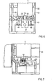
- An example of such a rigid attachment is shown in FIG. 6 in a view and FIG. 7 partially in section on the side.
- a support body made of insulating material is designated 40.
- Side walls 41 and 42 and a floor 43 delimit a space provided for receiving the switching tube 1, which, as FIG. 6 shows, is open towards the front.
- On the bottom 43 there is a connection bracket 44 which has a fastening leg 45 and a clamping bracket 47 which is at right angles thereto.
- the fastening leg 45 is provided with bores for the passage of fastening screws 46 and a central holding screw 48.
- the connection bracket 44 On both sides of the bore 50 provided for receiving the retaining screw 48, the connection bracket 44 has webs 51, between which the fixed connection bolt 51 of the switching tube 1 is received.
- the connecting pin is expediently provided on both sides with flats 52 in order to preclude rotatability of the switching tube, and contains a threaded bore 54 accessible on the end face 53.
- the switching tube 1 rests with the flat end face 53 of its connecting bolt 5 on the flat fastening leg 45 of the connecting angle 44.
- Die Retaining screw 8 establishes the rigid mechanical connection between the switching tube and the connection bracket 44 and at the same time ensures a low-loss current transfer between these parts.
- This type of attachment of the switching tube requires a considerably reduced effort compared to the ball joints required previously, for example in accordance with GB-A-2 095 476, and at the same time ensures that operational or external stresses, such as heating, switching forces and impacts, have no effect on the position the switching tube remain inside the switching device.
- connection angle can also be attached to the underside of the base 43 without any change in the parts, as a result of which the clamping angle 47 is given the position indicated by dash-dotted lines in FIG. It is then possible to use a switching tube with a greater axial length, a spacer being able to be inserted between the end face 53 and the fastening leg 45 to compensate for different dimensions.
- the joint arrangement described is particularly suitable for vacuum switching devices that have a very high, ie. H. should reach more than 1 million operating cycles without maintenance.
- Such switching devices are, for example, contactors for the voltage range of approximately 1-15 kV, as are used for switching high-voltage motors and similar consumers on and off.
Landscapes
- High-Tension Arc-Extinguishing Switches Without Spraying Means (AREA)
- Driving Mechanisms And Operating Circuits Of Arc-Extinguishing High-Tension Switches (AREA)
Applications Claiming Priority (2)
| Application Number | Priority Date | Filing Date | Title |
|---|---|---|---|
| DE3328183 | 1983-08-01 | ||
| DE19833328183 DE3328183A1 (de) | 1983-08-01 | 1983-08-01 | Antrieb fuer einen vakuumschalter |
Publications (2)
| Publication Number | Publication Date |
|---|---|
| EP0136253A1 true EP0136253A1 (fr) | 1985-04-03 |
| EP0136253B1 EP0136253B1 (fr) | 1987-01-28 |
Family
ID=6205794
Family Applications (1)
| Application Number | Title | Priority Date | Filing Date |
|---|---|---|---|
| EP84730080A Expired EP0136253B1 (fr) | 1983-08-01 | 1984-07-31 | Dispositif moteur pour interrupteur à vide |
Country Status (5)
| Country | Link |
|---|---|
| US (1) | US4621175A (fr) |
| EP (1) | EP0136253B1 (fr) |
| JP (1) | JPS60501926A (fr) |
| DE (2) | DE3328183A1 (fr) |
| WO (1) | WO1985000691A1 (fr) |
Cited By (2)
| Publication number | Priority date | Publication date | Assignee | Title |
|---|---|---|---|---|
| US5069077A (en) * | 1989-05-11 | 1991-12-03 | Siemens Aktiengesellschaft | Actuating mechanism for a vacuum-type interrupter with a contact spring |
| DE9111371U1 (de) * | 1991-09-10 | 1993-01-21 | Siemens AG, 8000 München | Elektrisch isolierende Antriebsstange für Hochspannungsschalter |
Families Citing this family (2)
| Publication number | Priority date | Publication date | Assignee | Title |
|---|---|---|---|---|
| DE9213143U1 (de) * | 1992-09-25 | 1993-03-25 | Siemens AG, 8000 München | Vakuumschütz mit einer Anschlußvorrichtung |
| US5474156A (en) * | 1994-07-01 | 1995-12-12 | Arctco, Inc. | Module connection alignment system |
Citations (4)
| Publication number | Priority date | Publication date | Assignee | Title |
|---|---|---|---|---|
| US3214550A (en) * | 1962-05-02 | 1965-10-26 | Westinghouse Electric Corp | Circuit interrupters with crossbars captively related to piston structures |
| US3267247A (en) * | 1963-07-15 | 1966-08-16 | Hugh C Ross | Vacuum switch |
| US3501180A (en) * | 1968-09-16 | 1970-03-17 | Visi Trol Eng Co | Coupling to provide angular and lateral orientation |
| GB2095476A (en) * | 1981-03-20 | 1982-09-29 | Siemens Ag | Vacuum switching devices |
Family Cites Families (2)
| Publication number | Priority date | Publication date | Assignee | Title |
|---|---|---|---|---|
| US1875575A (en) * | 1930-08-30 | 1932-09-06 | Eckhard John | Actuating means for shock absorbers |
| US2984249A (en) * | 1957-12-16 | 1961-05-16 | Jr Isaac W Sears | Umbrella structure |
-
1983
- 1983-08-01 DE DE19833328183 patent/DE3328183A1/de not_active Withdrawn
-
1984
- 1984-07-31 JP JP59503089A patent/JPS60501926A/ja active Pending
- 1984-07-31 US US06/720,410 patent/US4621175A/en not_active Expired - Fee Related
- 1984-07-31 WO PCT/DE1984/000163 patent/WO1985000691A1/fr not_active Ceased
- 1984-07-31 DE DE8484730080T patent/DE3462295D1/de not_active Expired
- 1984-07-31 EP EP84730080A patent/EP0136253B1/fr not_active Expired
Patent Citations (4)
| Publication number | Priority date | Publication date | Assignee | Title |
|---|---|---|---|---|
| US3214550A (en) * | 1962-05-02 | 1965-10-26 | Westinghouse Electric Corp | Circuit interrupters with crossbars captively related to piston structures |
| US3267247A (en) * | 1963-07-15 | 1966-08-16 | Hugh C Ross | Vacuum switch |
| US3501180A (en) * | 1968-09-16 | 1970-03-17 | Visi Trol Eng Co | Coupling to provide angular and lateral orientation |
| GB2095476A (en) * | 1981-03-20 | 1982-09-29 | Siemens Ag | Vacuum switching devices |
Non-Patent Citations (1)
| Title |
|---|
| SACE S.p.A. - Costruzioni elettromeccaniche - Bergamo, IT., Cat 8-0/12-1980; VRC; Unimotor HV; * |
Cited By (2)
| Publication number | Priority date | Publication date | Assignee | Title |
|---|---|---|---|---|
| US5069077A (en) * | 1989-05-11 | 1991-12-03 | Siemens Aktiengesellschaft | Actuating mechanism for a vacuum-type interrupter with a contact spring |
| DE9111371U1 (de) * | 1991-09-10 | 1993-01-21 | Siemens AG, 8000 München | Elektrisch isolierende Antriebsstange für Hochspannungsschalter |
Also Published As
| Publication number | Publication date |
|---|---|
| EP0136253B1 (fr) | 1987-01-28 |
| WO1985000691A1 (fr) | 1985-02-14 |
| US4621175A (en) | 1986-11-04 |
| DE3462295D1 (en) | 1987-03-05 |
| JPS60501926A (ja) | 1985-11-07 |
| DE3328183A1 (de) | 1985-02-21 |
Similar Documents
| Publication | Publication Date | Title |
|---|---|---|
| DE2927423C2 (de) | Zweikreisdruckregler | |
| DE69607266T2 (de) | Durch einen Motor betätigte Widerstands-Punktschweisszange vom Scherentyp | |
| EP0172986A2 (fr) | Dispositif de commande pour un interrupteur électrique à contacts à pression, en particulier pour un interrupteur sous vide | |
| EP0159960B1 (fr) | Appareil interrupteur sous vide avec un dispositif d'entraînement ainsi qu'un ressort qui s'appuie sur le plot de contact mobile du tube interrupteur | |
| EP0606265B1 (fr) | Interrupteur a vide multipolaire avec une unite d'entrainement polaire pour chaque tube commutateur a vide | |
| DE3412318C2 (fr) | ||
| EP0136253B1 (fr) | Dispositif moteur pour interrupteur à vide | |
| DE19716720A1 (de) | Betätigungs-Einrichtung für eine längenverstellbare Gasfeder | |
| DE3906786C2 (fr) | ||
| DE10048659A1 (de) | Schaltkontaktanordnung eines Niederspannungs-Leistungsschalter mit Kontaktkraftfedern | |
| EP0354445B1 (fr) | Chambre de coupure d'un interrupteur à vide | |
| EP0632928B1 (fr) | Interrupteur a vide avec un montage en boucle de courant | |
| DE563635C (de) | Schalteinrichtung fuer ein Arbeiten mit besonders grosser Schalthaeufigkeit | |
| DE3145629C2 (fr) | ||
| DE4227353A1 (de) | Steuergriffanordnung, insbesondere zur Verwendung mit einer druckmittelbetriebenen Steuergeberanordnung | |
| EP0308862A2 (fr) | Sectionneur haute-tension | |
| EP0003352A1 (fr) | Dispositif d'entraînement pour interrupteurs | |
| WO2025218966A1 (fr) | Joint rotatif avec un dispositif d'amortissement, support latéral comprenant un joint rotatif, système de ligne aérienne contenant un support latéral, et procédé de réglage de l'amortissement d'un support latéral | |
| DE1129586B (fr) | ||
| CH377879A (de) | Gefederte Wippe an einem Stromabnehmer für elektrische Fahrzeuge | |
| DE3210966A1 (de) | Phasenschraubklemme | |
| CH335331A (de) | Einsäulen-Scherentrennschalter | |
| DE8717533U1 (de) | Druck- oder Zugstange aus faserverstärktem Isolierstoff | |
| DE9015368U1 (de) | Elektrischer Hochspannungs-Leistungsschalter, insbesondere Druckgasschalter | |
| DE3246714A1 (de) | Elektrischer schalter, insbesondere lenkstockschalter fuer kraftfahrzeuge |
Legal Events
| Date | Code | Title | Description |
|---|---|---|---|
| PUAI | Public reference made under article 153(3) epc to a published international application that has entered the european phase |
Free format text: ORIGINAL CODE: 0009012 |
|
| AK | Designated contracting states |
Designated state(s): DE FR GB IT |
|
| 17P | Request for examination filed |
Effective date: 19850426 |
|
| 17Q | First examination report despatched |
Effective date: 19860418 |
|
| GRAA | (expected) grant |
Free format text: ORIGINAL CODE: 0009210 |
|
| AK | Designated contracting states |
Kind code of ref document: B1 Designated state(s): DE FR GB IT |
|
| REF | Corresponds to: |
Ref document number: 3462295 Country of ref document: DE Date of ref document: 19870305 |
|
| ET | Fr: translation filed | ||
| ITF | It: translation for a ep patent filed | ||
| PLBE | No opposition filed within time limit |
Free format text: ORIGINAL CODE: 0009261 |
|
| STAA | Information on the status of an ep patent application or granted ep patent |
Free format text: STATUS: NO OPPOSITION FILED WITHIN TIME LIMIT |
|
| 26N | No opposition filed | ||
| PGFP | Annual fee paid to national office [announced via postgrant information from national office to epo] |
Ref country code: FR Payment date: 19900724 Year of fee payment: 7 |
|
| ITTA | It: last paid annual fee | ||
| PG25 | Lapsed in a contracting state [announced via postgrant information from national office to epo] |
Ref country code: FR Effective date: 19920331 |
|
| REG | Reference to a national code |
Ref country code: FR Ref legal event code: ST |
|
| PGFP | Annual fee paid to national office [announced via postgrant information from national office to epo] |
Ref country code: GB Payment date: 19970620 Year of fee payment: 14 |
|
| PGFP | Annual fee paid to national office [announced via postgrant information from national office to epo] |
Ref country code: DE Payment date: 19970918 Year of fee payment: 14 |
|
| PG25 | Lapsed in a contracting state [announced via postgrant information from national office to epo] |
Ref country code: GB Free format text: LAPSE BECAUSE OF NON-PAYMENT OF DUE FEES Effective date: 19980731 |
|
| GBPC | Gb: european patent ceased through non-payment of renewal fee |
Effective date: 19980731 |
|
| PG25 | Lapsed in a contracting state [announced via postgrant information from national office to epo] |
Ref country code: DE Free format text: LAPSE BECAUSE OF NON-PAYMENT OF DUE FEES Effective date: 19990501 |