EP0136361A1 - Appareil permettant de faire varier la largeur de voie d'un tracteur agricole - Google Patents
Appareil permettant de faire varier la largeur de voie d'un tracteur agricole Download PDFInfo
- Publication number
- EP0136361A1 EP0136361A1 EP84901005A EP84901005A EP0136361A1 EP 0136361 A1 EP0136361 A1 EP 0136361A1 EP 84901005 A EP84901005 A EP 84901005A EP 84901005 A EP84901005 A EP 84901005A EP 0136361 A1 EP0136361 A1 EP 0136361A1
- Authority
- EP
- European Patent Office
- Prior art keywords
- hub
- outer ring
- threads
- screw
- axle
- Prior art date
- Legal status (The legal status is an assumption and is not a legal conclusion. Google has not performed a legal analysis and makes no representation as to the accuracy of the status listed.)
- Withdrawn
Links
Images
Classifications
-
- B—PERFORMING OPERATIONS; TRANSPORTING
- B60—VEHICLES IN GENERAL
- B60B—VEHICLE WHEELS; CASTORS; AXLES FOR WHEELS OR CASTORS; INCREASING WHEEL ADHESION
- B60B19/00—Wheels not otherwise provided for or having characteristics specified in one of the subgroups of this group
-
- B—PERFORMING OPERATIONS; TRANSPORTING
- B60—VEHICLES IN GENERAL
- B60B—VEHICLE WHEELS; CASTORS; AXLES FOR WHEELS OR CASTORS; INCREASING WHEEL ADHESION
- B60B27/00—Hubs
- B60B27/0015—Hubs for driven wheels
- B60B27/0021—Hubs for driven wheels characterised by torque transmission means from drive axle
- B60B27/0031—Hubs for driven wheels characterised by torque transmission means from drive axle of the axial type, e.g. front teeth
-
- B—PERFORMING OPERATIONS; TRANSPORTING
- B60—VEHICLES IN GENERAL
- B60B—VEHICLE WHEELS; CASTORS; AXLES FOR WHEELS OR CASTORS; INCREASING WHEEL ADHESION
- B60B27/00—Hubs
- B60B27/06—Hubs adapted to be fixed on axle
- B60B27/065—Hubs adapted to be fixed on axle characterised by the fixation of the hub to the axle
-
- B—PERFORMING OPERATIONS; TRANSPORTING
- B60—VEHICLES IN GENERAL
- B60B—VEHICLE WHEELS; CASTORS; AXLES FOR WHEELS OR CASTORS; INCREASING WHEEL ADHESION
- B60B35/00—Axle units; Parts thereof ; Arrangements for lubrication of axles
- B60B35/02—Dead axles, i.e. not transmitting torque
- B60B35/10—Dead axles, i.e. not transmitting torque adjustable for varying track
- B60B35/1009—Dead axles, i.e. not transmitting torque adjustable for varying track operated manually
-
- B—PERFORMING OPERATIONS; TRANSPORTING
- B60—VEHICLES IN GENERAL
- B60B—VEHICLE WHEELS; CASTORS; AXLES FOR WHEELS OR CASTORS; INCREASING WHEEL ADHESION
- B60B35/00—Axle units; Parts thereof ; Arrangements for lubrication of axles
- B60B35/02—Dead axles, i.e. not transmitting torque
- B60B35/10—Dead axles, i.e. not transmitting torque adjustable for varying track
- B60B35/1036—Dead axles, i.e. not transmitting torque adjustable for varying track operated with power assistance
-
- B—PERFORMING OPERATIONS; TRANSPORTING
- B60—VEHICLES IN GENERAL
- B60B—VEHICLE WHEELS; CASTORS; AXLES FOR WHEELS OR CASTORS; INCREASING WHEEL ADHESION
- B60B35/00—Axle units; Parts thereof ; Arrangements for lubrication of axles
- B60B35/02—Dead axles, i.e. not transmitting torque
- B60B35/10—Dead axles, i.e. not transmitting torque adjustable for varying track
- B60B35/1072—Dead axles, i.e. not transmitting torque adjustable for varying track by transversally movable elements
- B60B35/1081—Dead axles, i.e. not transmitting torque adjustable for varying track by transversally movable elements the element is a wheel
-
- B—PERFORMING OPERATIONS; TRANSPORTING
- B60—VEHICLES IN GENERAL
- B60B—VEHICLE WHEELS; CASTORS; AXLES FOR WHEELS OR CASTORS; INCREASING WHEEL ADHESION
- B60B35/00—Axle units; Parts thereof ; Arrangements for lubrication of axles
- B60B35/12—Torque-transmitting axles
- B60B35/121—Power-transmission from drive shaft to hub
-
- B—PERFORMING OPERATIONS; TRANSPORTING
- B62—LAND VEHICLES FOR TRAVELLING OTHERWISE THAN ON RAILS
- B62D—MOTOR VEHICLES; TRAILERS
- B62D49/00—Tractors
- B62D49/06—Tractors adapted for multi-purpose use
- B62D49/0678—Tractors of variable track width or wheel base
-
- B—PERFORMING OPERATIONS; TRANSPORTING
- B60—VEHICLES IN GENERAL
- B60B—VEHICLE WHEELS; CASTORS; AXLES FOR WHEELS OR CASTORS; INCREASING WHEEL ADHESION
- B60B2310/00—Manufacturing methods
- B60B2310/30—Manufacturing methods joining
- B60B2310/305—Manufacturing methods joining by screwing
-
- B—PERFORMING OPERATIONS; TRANSPORTING
- B60—VEHICLES IN GENERAL
- B60Y—INDEXING SCHEME RELATING TO ASPECTS CROSS-CUTTING VEHICLE TECHNOLOGY
- B60Y2200/00—Type of vehicle
- B60Y2200/20—Off-Road Vehicles
- B60Y2200/22—Agricultural vehicles
- B60Y2200/221—Tractors
Definitions
- the present invention relates to a farm tractor and more particularly to a farm tractor tread (the distance between the two front wheels or two rear wheels of a tractor) adjustment device which can quickly vary or adjust the tread depending upon a furrow width in a very simple manner.
- the tread of a farm tractor When a field work is carried out by farm tractors, the tread of a farm tractor must be varied or adjusted depending upon a furrow width.
- a conventional tread adjustment method first, an agriculture equipment is disconnected from a farm tractor and then the rear portion of the farm tractor is lifted by means of a jack. Thereafter eight rear hub bolts must be removed so that a wheel disk which interconnects between an axle and a wheel is removed from a hub portion of the axle.
- rim bolts in general, eight bolts
- the point at which the wheel disk and the rim are interconnected is varied (joint means are provided for the rim at various points in the axial direction so that the point of joint between the wheel disk and rim may be varied) and then the wheel disk and the rim are assembled again. Thereafter, the wheel disk is securely joined to the axle and then the jack is removed and a desired agricultural equipment is attached to the farm tractor. In some cases, the right and left tires are exchanged with each other.
- Such tread adjustment method as described above takes a long period of time and is cumbersome and extremely inefficient.
- a drum-shaped hub is mounted at the end of an axle and the barrel or cylindrical portion of the hub is formed with male. screw-threads which are engaged with female screw-threads formed on the inner surface of the boss portion of an outer ring carrying a tire so that the outer ring can be securely held at a predetermined position on the barrel or cylindrical portion of the hub by holding means.
- a flange is formed at the inner end of the barrel or cylindrical portion of the hub and a stopper plate is detachably attached to the outer end of the barrel or cylindrical portion of the hub.
- an annular spacer ring is interposed between the outer ring and the flange at the inner end of the hub or between the outer ring and the stop plate.
- spacer rings are interposed between the outer ring and the flange at the inner end of the hub and between the outer ring and the stop plate.
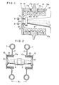
- reference numeral 10 designates a specially fabricated drum type hub which has a flange 10a at its inner end and an end plate 10c at its outer end.
- the end plate 10c is formed with holes 13 through which are extended hub bolts 12 which in turn are extended outwardly from the outer end of an axle A extending through a casing C.
- the cylindrical barrel portion 10b of the hub 10 is formed with male screw-threads 14 of a relatively large pitch and a ring-shaped or annular stop plate 15 is detachably attached by screw-threads to the outer end portion of the barrel portion 10b of the hub 10 in an opposed relationship with the inner flange 10a.
- the stop plate 15 may be so designed and constructed that it may securely be joined to the outer end of the barrel portion 10b of the hub 10 with bolts.
- An outer ring 17, which corresponds to a conventional wheel disk, is screw-engaged with the barrel portion 10b of the hub 10 and the inner surface of the boss portion 17a of the outer ring 17 is formed with female screw-threads 18 engageable with the male screw-threads 14 of the barrel portion 10b of the hub 10.
- the outer ring 17 must be engaged with the barrel portion 10b of the hub 10 and then securely held at a predetermined portion.
- Ring-shaped or annular spacer rings 19 engageable with the barrel portion 10b of the hub 10 are used as one means for securely holding the outer ring 17 in position.
- the widths of the spacer rings 19 are selected.
- the spacer rings 17 are selectively disposed between the flange 10a of the hub 10 and the outer ring 17 and/or between the outer ring 17 and the stop plate 15 so that the position of the outer ring 17 is determined.
- the spacer rings 19 are made of, for instance, cast iron.
- Buffer plates 17b are disposed at suitable positions of the side surfaces of the boss portion l7a of the outer ring 17 so that the side surfaces of the spacer rings 19 and the boss portion 17a can be prevented from being pressed too strongly against each other. Consequently, the spacer rings 17 can be displaced in the peripheral directions of the side surfaces of the boss portion 17a of the outer ring 17.
- the hub 10 is caused to rotate so that the outer ring 17 is caused to shift toward the right or left.
- the brakes can be applied to the right and left wheels independently of each other, when the wheel which is not adjusted is braked and then the axle A is rotated, the outer ring 17 can shift while' the tractor is held stationary.
- the position of the outer ring 17 can be arbitrarily selected.
- the right and left tires T (that is, the right and left outer rings 17) can be moved toward or away from each other when the tractor is.advanced forwardly or rearwardly so that the positions of the right and left outer rings 17 can be simultaneously adjusted. More particularly, when the axle A is rotated while both the right and left tires T are kept in contact with the ground, the male and female screw-threads 14 and 18 slide each other to move the right and left outer rings 17 toward or away from each other.
- the outer spacer ring 17 is fitted on the barrel portion 10b of the hub 10 outwardly of the outer ring 17 and thereafter the stop plate 15 is screw-engaged with the outer end portion of the barrel portion 10b of the hub 10.
- the outer ring 17 can be securely held in position on the hub 10 by attaching the stop plate 15.
- the buffer plates 17b are provided on the side surfaces of the boss portion 17a of the outer ring 17, the side surfaces of the spacer rings 19 can be easily separated from the side surfaces of the boss portion 17a of the outer ring 17. Therefore, the operation for separating the spacer rings 19 from the outer ring 17 is much faciliated.
- the buffer plates 17b are movable in the peripheral directions along the side surfaces of the outer ring 17, the separation between the spacer rings 17 and the outer ring 17 can be much facilitated.
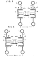
- Figs. 2 to 4 show three tread adjustment cases, respectively.
- Fig. 2 shows a case wherein the tread is set in the narrowest width (W 1 ).
- W 1 narrowest width
- each outer ring 17 contacts the inner flange 10a of the hub 10 and two space rings 19 are interposed in series between the outer ring 17 and the stop plate 15.
- Fig. 3 shows a case wherein the tread is set in the intermediate width (W 2 ) as in the case of Fig. 1.
- the right and left spacer rings 19 are disposed inwardly and outwardly of the outer ring 17, respectively.
- Fig. 4 shows a case wherein the tread is set in the widest width (W 3 ).
- each outer ring 17 contacts the stop plate 15 and two spacer rings 19 are interposed in series between the outer ring 17 and the inner flange 10a of the hub 10.
- the tread adjustment time can be reduced to about 1/20.
- furrow widths are determined as 60 cm, 66 cm and 72 cm.
- the tread can be varied in three widths as described above with reference to Figs. 2 to 4, an operator can easily and safely adjust the tractor tread depending upon the selected furrow.
- the spacer rings 19 are selectively disposed in series or spaced apart from each other if the widths of spacer rings are suitably selected. If only two spacer rings 19 are provided with respect to one hub 10, it is not necessary to use a spacer ring with a wider width even when the outer ring 17 is set in contact with the inner flange 10a of the hub or with the stop plate 15.
- the farm tractor tread adjustment device in accordance with the present invention is useful in various farm lands with different furrow widths. Especially when the area of a farm land is limited, the farm tractor tread adjustment device in accordance with the present invention is most advantageously adapted because the tread can be easily and quickly varied depending upon a furrow width.
Landscapes
- Engineering & Computer Science (AREA)
- Mechanical Engineering (AREA)
- Chemical & Material Sciences (AREA)
- Combustion & Propulsion (AREA)
- Transportation (AREA)
- Arrangement And Driving Of Transmission Devices (AREA)
- Agricultural Machines (AREA)
- Harvester Elements (AREA)
Abstract
Un moyeu en forme de tambour (10) est fixé à l'extrémité d'un essieu A d'un tracteur, et un anneau extérieur (17) qui retient le pneumatique est vissé sur une partie du moyeu en forme de tambour. L'anneau extérieur (17) est situé en un point prédéterminé sur la partie du moyeu et y est attaché par des dispositifs de fixation (10a, 15, 19). Lorsque l'essieu A du tracteur est tourné dans une position dans laquelle les dispositifs de fixation sont enlevés et l'anneau extérieur (17) est vissé sur la partie du moyeu en forme de tambour, la position de l'anneau extérieur (17) le long de la partie du moyeu en forme de tambour varie, permettant ainsi un ajustage aisé de la largeur de voie.
Applications Claiming Priority (2)
| Application Number | Priority Date | Filing Date | Title |
|---|---|---|---|
| JP28092/83U | 1983-03-01 | ||
| JP2809283U JPS59135205U (ja) | 1983-03-01 | 1983-03-01 | 農業用トラクタ−の車輪幅変装置 |
Publications (2)
| Publication Number | Publication Date |
|---|---|
| EP0136361A1 true EP0136361A1 (fr) | 1985-04-10 |
| EP0136361A4 EP0136361A4 (fr) | 1985-07-30 |
Family
ID=12239139
Family Applications (1)
| Application Number | Title | Priority Date | Filing Date |
|---|---|---|---|
| EP19840901005 Withdrawn EP0136361A4 (fr) | 1983-03-01 | 1984-03-01 | Appareil permettant de faire varier la largeur de voie d'un tracteur agricole. |
Country Status (3)
| Country | Link |
|---|---|
| EP (1) | EP0136361A4 (fr) |
| JP (1) | JPS59135205U (fr) |
| WO (1) | WO1984003476A1 (fr) |
Family Cites Families (5)
| Publication number | Priority date | Publication date | Assignee | Title |
|---|---|---|---|---|
| US2685478A (en) * | 1949-05-19 | 1954-08-03 | Morris F Booth | Tractor wheel locator |
| DE811786C (de) * | 1950-04-04 | 1951-08-23 | Bernhard Bruns | Vorrichtung zur Verstellung der Spurweite von Fahrzeugen, insbesondere Treckern |
| US2722988A (en) * | 1953-11-12 | 1955-11-08 | Ford Motor Co | Tractor wheel spacing means |
| JPS4317608Y1 (fr) * | 1965-06-10 | 1968-07-22 | ||
| JPS5411618Y2 (fr) * | 1976-05-08 | 1979-05-24 |
-
1983
- 1983-03-01 JP JP2809283U patent/JPS59135205U/ja active Granted
-
1984
- 1984-03-01 WO PCT/JP1984/000075 patent/WO1984003476A1/fr not_active Ceased
- 1984-03-01 EP EP19840901005 patent/EP0136361A4/fr not_active Withdrawn
Also Published As
| Publication number | Publication date |
|---|---|
| WO1984003476A1 (fr) | 1984-09-13 |
| JPH038481Y2 (fr) | 1991-03-01 |
| JPS59135205U (ja) | 1984-09-10 |
| EP0136361A4 (fr) | 1985-07-30 |
Similar Documents
| Publication | Publication Date | Title |
|---|---|---|
| US2472742A (en) | Adjustable axle and wheel assembly | |
| US2324681A (en) | Adjustable tractor wheel mounting means | |
| US2467482A (en) | Adjustable wheel mount | |
| EP0136361A1 (fr) | Appareil permettant de faire varier la largeur de voie d'un tracteur agricole | |
| DE69615785T2 (de) | Wendehilfsmechanismus für ein Fahrzeug | |
| DE2359636A1 (de) | Luftrad fuer fahrzeuge | |
| GB2285957B (en) | Wheel | |
| US2546453A (en) | Adjustable tractor wheel means | |
| DE1164257B (de) | Auf einem Radstern loesbar befestigte Felge fuer luftbereifte Gelaende-Fahrzeuge | |
| US2432385A (en) | Wheel with axially adjustable rim | |
| US3208798A (en) | Safety wheel | |
| US2819117A (en) | Axle adapter for adjustable wheel | |
| EP0084979A2 (fr) | Dispositif de couplage de roues jumelles | |
| US2552168A (en) | Cleat attachment for tractor wheels | |
| US2335372A (en) | Tractor wheel | |
| US2204650A (en) | Traction wheel | |
| EP0021649A2 (fr) | Appareil pour fixation d'une roue | |
| US4029423A (en) | Free-wheeling spindle adaptor | |
| US3359039A (en) | Dual wheel attachment for tractors | |
| GB1498639A (en) | Fastening construction for detachably connecting an additional wheel rim or cage wheel to a wheel of a tractor or other heavy duty vehicle | |
| US3953075A (en) | Auxiliary wheel mounting | |
| DE1296030B (de) | Zwillingsradanordnung bei mit luftbereiften Raedern ausgeruesteten Fahrzeugen und Fahrzeuganhaengern | |
| US3029862A (en) | Tire demounting apparatus | |
| US1849464A (en) | Demountable wheel rim assembly | |
| US6179388B1 (en) | Method of making a wheel |
Legal Events
| Date | Code | Title | Description |
|---|---|---|---|
| PUAI | Public reference made under article 153(3) epc to a published international application that has entered the european phase |
Free format text: ORIGINAL CODE: 0009012 |
|
| 17P | Request for examination filed |
Effective date: 19841031 |
|
| AK | Designated contracting states |
Designated state(s): DE FR GB NL |
|
| 17Q | First examination report despatched |
Effective date: 19860620 |
|
| STAA | Information on the status of an ep patent application or granted ep patent |
Free format text: STATUS: THE APPLICATION IS DEEMED TO BE WITHDRAWN |
|
| 18D | Application deemed to be withdrawn |
Effective date: 19861231 |
|
| RIN1 | Information on inventor provided before grant (corrected) |
Inventor name: FUKUZAWA, KAZUHIKOFUKUZAWA TRACTOR K. K. |