EP0136370B1 - Hydraulisches Steuersystem für eine Überbrückungskupplung - Google Patents
Hydraulisches Steuersystem für eine Überbrückungskupplung Download PDFInfo
- Publication number
- EP0136370B1 EP0136370B1 EP83109912A EP83109912A EP0136370B1 EP 0136370 B1 EP0136370 B1 EP 0136370B1 EP 83109912 A EP83109912 A EP 83109912A EP 83109912 A EP83109912 A EP 83109912A EP 0136370 B1 EP0136370 B1 EP 0136370B1
- Authority
- EP
- European Patent Office
- Prior art keywords
- lock
- spool
- clutch
- valve
- fluid pressure
- Prior art date
- Legal status (The legal status is an assumption and is not a legal conclusion. Google has not performed a legal analysis and makes no representation as to the accuracy of the status listed.)
- Expired
Links
- 239000012530 fluid Substances 0.000 claims description 28
- 230000005540 biological transmission Effects 0.000 claims description 11
- XDDAORKBJWWYJS-UHFFFAOYSA-N glyphosate Chemical group OC(=O)CNCP(O)(O)=O XDDAORKBJWWYJS-UHFFFAOYSA-N 0.000 claims description 9
- 239000000446 fuel Substances 0.000 description 2
- 230000001133 acceleration Effects 0.000 description 1
- 238000010276 construction Methods 0.000 description 1
- 230000003247 decreasing effect Effects 0.000 description 1
- 230000001419 dependent effect Effects 0.000 description 1
- 230000000994 depressogenic effect Effects 0.000 description 1
- 238000010586 diagram Methods 0.000 description 1
- 239000003607 modifier Substances 0.000 description 1
Images


Classifications
-
- F—MECHANICAL ENGINEERING; LIGHTING; HEATING; WEAPONS; BLASTING
- F16—ENGINEERING ELEMENTS AND UNITS; GENERAL MEASURES FOR PRODUCING AND MAINTAINING EFFECTIVE FUNCTIONING OF MACHINES OR INSTALLATIONS; THERMAL INSULATION IN GENERAL
- F16H—GEARING
- F16H61/00—Control functions within control units of change-speed- or reversing-gearings for conveying rotary motion ; Control of exclusively fluid gearing, friction gearing, gearings with endless flexible members or other particular types of gearing
- F16H61/14—Control of torque converter lock-up clutches
- F16H61/143—Control of torque converter lock-up clutches using electric control means
Definitions
- the present invention relates to a hydraulic control system for a lock-up clutch of a hydrodynamic device of an automatic transmission for a vehicle, according to the preamble part of claim 1.
- the second problem is in that the engine revolution speed during coasting operation is elevated when the lock-up clutch is engaged as compared to the case when the lock-up clutch is not engaged and thus fuel economy during coasting operation is poor as compared to the latter case.
- the engine revolution speed is elevated because there is no slip when the lock-up clutch is engaged during coasting operation.
- a hydraulic control system is known from EP-A-0 067 594.
- This known system comprises a lock- up control valve having a spool movable between a non-lock-up position and a lock-up position.
- Means in the form of an oil passage are provided for hydraulically engaging the lock-up clutch when said spool assumes said lock-up position and releasing the lock-up clutch when said spool assumes said non-lockup position.
- Further means in the form of a governor pressure line leading to the lock-up control valve are adapted for hydraulically actuating said spool of said lock-up control valve towards said lock-up position thereof in accordance with a predetermined basic mode of lock-up operation, i.e.
- Means being constituted by a clutch release preventing mechanism, a first control line, a second control line, a fourth control valve and a clutch release mechanism include the aforementioned solenoid operable responsive to said output signal for forcibly disengaging said lock-up clutch.
- the lock-up control valve is designed to assume the lock-up position thereof to allow line fluid pressure to be supplied to the lock-up clutch when the vehicle speed exceeds a predetermined value as is shown in Fig. 4.
- the aforementioned three spool valves are provided. These valves are not fluidly disposed in the governor fluid pressure line leading to the lock-up control valve and thus, do not constitute any element of the hydraulical actuating means.
- One valve is disopsed between the lock-up clutch and the lock-up control valve and has a bias port connected to a throttle fluid pressure line and operates such that when the throttle opening degree assumes a value as indicated by the line segment C in Fig. 4, it is shifted from its spring set position to a second position where the fluid pressure is discharged from the lock-up clutch, thereby disengaging same. Even if the throttle opening degree is above the line segment C, it is preferable to engage the lock-up clutch.
- another of the three valves is disposed in the throttle fluid pressure line to , discharge the throttle fluid pressure from the beforementioned valve when the vehicle speed is indicated by the governor fluid pressure in the line leading to the lock-up control valve exceeds a value as indicated by line segment D.
- the third valve actuable by the solenoid is disposed in the throttle fluid pressure line between the beforementioned two valves. The solenoid actuates the third valve when the accelerator is released below a throttle opening degree as indicated by line segment F in Fig. 4, thus allowing the supply of line fluid pressure, instead of throttle fluid pressure, to the first valve, which is shifted to the position where the lock-up clutch is disengaged.
- FIG. 1 there is shown a schematic view of a power transmission mechanism of a three-speed automatic transmission having three forward speed ratios and one reverse speed ratio.
- This power transmission comprises an input shaft I to which rotary power is delivered from an engine output shaft E via a torque converter T/C, an output shaft O which transmits driving power to a final drive, a first planetary gear set G1, a second planetary gear set G2, a front clutch F/C, a rear clutch R/C, a band brake B, a low and reverse brake L & R/B, and one-way clutch OWC.
- the first planetary gear set G1 comprises an internal gear R1, a sun gear S1, and a carrier PC1 carrying pinion gears P1 meshing with the sun gear S1 and internal gear R1 simultaneously.
- the second planetary gear set G2 comprises an internal gear R2, a sun gear S2, and a carrier PC2 carrying pinion gears P2.
- the carrier PC1 is connected to an output shaft 0, while the sun gear S1 is connectable with an input shaft I via the front clutch (which may be called as a high and reverse clutch) F/C, and the internal gear R1 is connectable to the input shaft I via the raer clutch R/C.
- the internal gear R2 is connectd to the output shaft 0, and the sun gear S2 is connected to the sun gear S1.
- the carrier PC2 is prevented from rotating in its reverse direction by the one-way clutch OWC.
- a low and reverse brake L & R/B is arranged to anchor the carrier PC2.
- the band brake B is arranged to anchor the sun gears S1 and S2.
- This band brake B is actuated by a servo having a servo-apply chamber S/A and a servo-release chamber S/R.
- the band brake B is applied, while when the fluid pressure is applied to the servo-release chamber S/R, the band brake B is released irrespective of the presence of the fluid pressure in the servo apply chamber S/A.
- the torque converter T/C includes a pump impeller PI, a turbine runner T, a stator ST and a lock-up clutch L.
- the pump impeller PI is connected via a torque converter cover PI' to the engine output shaft E.
- the turbine runner T is connected to the input shaft I, and the stator ST is connected via a one-way clutch SOWC to a stationary portion of the transmission.
- the lock- up clutch L connected to the turbine runner T is axially movable and defines a lock-up clutch fluid pressure chamber LC in cooperation with the torque converter cover Pl'.
- the lock-up clutch L is pressed against the torque converter cover PI' when fluid pressure in the lock-up clutch fluid pressure chamber LC is lower than that within the torque converter T/C and rotates integrally with the torque converter cover Pl'.
- the detail construction of the lock-up clutch L is described in U.S. Patent No. 4,305,487 issued Dec. 15, 1981 to Sunohara.
- the front clutch F/C, rear clutch R/C, band brake B and low and reverse brake L & R/B are engageable in the predetermined combinations shown by the following Table to provide three forward speed ratios and one reverse speed ratio.
- the sign "o" indicates for each of clutches and brakes, the clutch or brake in question is engaged or applied.
- What is denoted by a label (OWC) below the brake B1 means that the first speed ratio is established by the one-way clutch OWC even if the brake B1 is not applied. However, in this first speed ratio, it is not possible for the output shaft O to drive the engine (that is, no engine braking is provided).
- What is indicated by the sign "o" in the column below B means that the servo apply chamber S/A and/or servo release chamber S/R in question are supplied with fluid pressure.
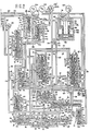
- the hydraulic control system comprises a regulator valve 1, a manual valve 2, a 1-2 shaft valve 3, a 2-3 shift valve 4, a 3-2 downshift valve 5, a line pressure booster valve 6, a pressure modifier valve 7, a throttle valve 8, a throttle fail-safe valve 9, a throttle modulator valve 10, a first manual range pressure reducing valve 11, an accumulator 12, a 3-2 timing valve 14, a front clutch pressure reducing. valve 15, governor valves 113, 114, a lock-up valve 17, a vehicle speed cut valve 18.
- valves are connected with the torque converter T/C, lock-up clutch fluid chamber LC, front clutch F/C, rear clutch R/C, servo apply chamber S/A of the band brake B, servo release chamber S/R of the band brake B, low and reverse brake L & R/B, and oil pump O/P.
- the hydraulic control system is substantially the same as that of European Pat. Appln. EP-A-59 425 filed Feb. 24, 1982 by Nissan Motor Co., Ltd. (see Fig. 2) and commonly assigned herewith.
- the hydraulic control system according to the present invention is different from that described in the European Pat. Appln. EP-A-59 425 in the provision of the lock-up valve 17 and speed cut valve 18 for controlling the lock-up clutch L.
- the vehicle speed cut valve 18 comprises a spool 22 slidably disposed in a valve bore 21 and a spring 23 biasing the spool 22 to the left as viewed in Fig. 3.
- the valve bore 21 is formed with five ports 21 a, 21b, 21c, 21d and 21e, while the spool 22 is formed with two lands 22a and 22b having the same diameter.
- the port 21 a communicates with an oil conduit 24 connected with the governor valve (113,114).
- the port 21d communicates with an oil conduit 29 connected with the high and reverse clutch F/C.
- the port 21c communicates via an oil conduit 25 with a port 26a of the lock-up valve 17.
- the port 21e communicates with an oil conduit 41 which is mentioned later.
- the port 21 b is a drain port.
- the lock-up valve 17 comprises a spool 27 slidably disposed in a valve bore 26, and a spring 28 biasing the spool 27 to the left as viewed in Fig. 3.
- the valve bore 26 is formed with five ports 26a, 26b, 26c, 26d and 26e, while the spool 27 is formed with two lands 27a and 27b having the same diameter.
- the port 26a communicates with the port 21c of the vehicle speed cut valve 18 as mentioned before.
- the port 26b communicates with an oil conduit 30 which supplies the torque converter T/C a pressurized oil from the regulator valve 1.
- the port 26c communicates via an oil conduit 31 with the lock-up clutch oil chamber LC.
- the ports 26d and 26e are drain ports, respectively.
- the torque converter supply pressure is supplied to the inside of the torque converter T/C from the oil conduit 30 and the oil within the torque converter T/C is discharged to an oil conduit 32.
- the oil in the oil conduit 32 is drained via a pressure maintaining valve 33.
- the lock-up oil chamber LC communicates with the oil conduit 31 as mentioned before.
- the solenoid valve 19 is arranged to open or close an opening 41a formed through the oil conduit 41 (i.e., an output oil conduit) which is connected via an orifice 43 with an oil conduit 42 which is supplied with a line fluid pressure from the regulator valve 1.
- the opening 41 a is closed or opened by a plunger 44a of a solenoid 44.
- the oil conduit 41 communicates with the port 21 e of the vehicle speed cut valve 18 as mentioned before.
- the solenoid 44 is electrically connected with an idle switch 45 which is actuated in response to an idle condition of the engine.
- the idle switch 45 is operatively mounted on an accelerator (see Fig. 1) and is closed or "ON" when no depression force is applied to the accelerator and otherwise "OFF".
- the solenoid 44 is "OFF", so that the oil within the oil conduit 41 is discharged through the opening 41 a and no pressure exists in the oil conduit 41. Therefore, the port 21e of the vehicle speed cut valve 18 is drained.
- the spool 4b of the 2-3 shift valve 4 is disposed in the position indicated by the right half thereof as viewed in Fig. 2 and no oil pressure is supplied to the high and reverse clutch F/C and thus no oil pressure exists in the oil conduit 29.
- no oil pressure acts through the oil conduit 25 on the port 26a of the lock-up valve 17 irrespective of the position of the vehicle speed cut valve 18. Therefore, the spool 27 of the lock-up valve 17 assumes the position indicated by the upper half thereof as viewed in Fig. 3 under the action of the spring 28.
- the spool 27 of the lock-up valve 17 switches to the position indicated by the bottom half thereof as viewed in Fig. 3.
- the port 26c is allowed to communicate with the port 26d which is a drain port and thus the oil within the lock-up clutch oil chamber LC is discharged through the oil conduit 31, thus putting the lock-up clutch into the engagement state thereof.
- the system operates in the following manner.
- the idle switch 45 is turned “ON” to put the solenoid 44 into “ON”.
- the solenoid 44 urges the plunger 44a to close the opening 41a.
- the oil pressure in the oil conduit 41 output oil pressure
- the line pressure acts on the port 21 e of the vehicle speed cut valve 18.
- the spool 22 of the vehicle speed cut valve 18 always switches to or is forced to assume the position indicated by the upper half thereof as viewed in Fig. 3, thus suspending the supply of the oil pressure to the oil conduit 25 so as to allow the spring 28 to push back the spool 28 of the lock-up valve 17 to the position indicated by the upper half thereof as viewed in Fig. 3. Therefore, the oil conduit 30 is allowed to communicate with the oil conduit 31 so as to release the lock-up clutch L.
- the lock-up clutch L is released always whenever the idle switch 45 is turned “ON”. Owing to this operation, the transmission of vibrations from the engine to the drive system is prevented. Further, since the engine revolution speed drops during coasting, the fuel economy improves.
- the solenoid 44 is electrically connected with a kickdown switch 45A as shown in Fig. 3.
- the kickdown switch 45a is turned “ON" when the accelerator pedal is depressed deeply into a kickdown state. If the solenoid 44 is electrically connected with the kickdown switch 45A, the lock-up clutch L is released at kickdown and engine revolution speed is elevated depending upon the degree of slip in the torque converter T/C and thus a torque multiplication by the torque converter is obtained. Therefore, a stronger acceleration is obtained for kickdown operation.
Landscapes
- Engineering & Computer Science (AREA)
- General Engineering & Computer Science (AREA)
- Mechanical Engineering (AREA)
- Control Of Fluid Gearings (AREA)
Claims (3)
Priority Applications (2)
| Application Number | Priority Date | Filing Date | Title |
|---|---|---|---|
| EP83109912A EP0136370B1 (de) | 1983-10-04 | 1983-10-04 | Hydraulisches Steuersystem für eine Überbrückungskupplung |
| DE8383109912T DE3379742D1 (en) | 1983-10-04 | 1983-10-04 | Hydraulic control system for lock-up clutch |
Applications Claiming Priority (1)
| Application Number | Priority Date | Filing Date | Title |
|---|---|---|---|
| EP83109912A EP0136370B1 (de) | 1983-10-04 | 1983-10-04 | Hydraulisches Steuersystem für eine Überbrückungskupplung |
Publications (2)
| Publication Number | Publication Date |
|---|---|
| EP0136370A1 EP0136370A1 (de) | 1985-04-10 |
| EP0136370B1 true EP0136370B1 (de) | 1989-04-26 |
Family
ID=8190721
Family Applications (1)
| Application Number | Title | Priority Date | Filing Date |
|---|---|---|---|
| EP83109912A Expired EP0136370B1 (de) | 1983-10-04 | 1983-10-04 | Hydraulisches Steuersystem für eine Überbrückungskupplung |
Country Status (2)
| Country | Link |
|---|---|
| EP (1) | EP0136370B1 (de) |
| DE (1) | DE3379742D1 (de) |
Citations (1)
| Publication number | Priority date | Publication date | Assignee | Title |
|---|---|---|---|---|
| EP0067594A1 (de) * | 1981-06-01 | 1982-12-22 | Honda Giken Kogyo Kabushiki Kaisha | Getriebe für Kraftfahrzeuge |
Family Cites Families (7)
| Publication number | Priority date | Publication date | Assignee | Title |
|---|---|---|---|---|
| JPS54132062A (en) * | 1978-04-04 | 1979-10-13 | Nissan Motor Co Ltd | Lock-up controlling apparatus for lock-up torque converter |
| US4289048A (en) * | 1978-09-11 | 1981-09-15 | Chrysler Corporation | Lock-up system for torque converter |
| DE2853115A1 (de) * | 1978-12-08 | 1980-06-26 | Bosch Gmbh Robert | Hydraulische steuervorrichtung zum schalten einer wandler-ueberbrueckungskupplung |
| DE3010509A1 (de) * | 1980-03-19 | 1981-09-24 | Volkswagenwerk Ag, 3180 Wolfsburg | Hydraulische steuereinrichtung fuer ein hydrodynamisch-mechanisches getriebe fuer kraftfahrzeuge |
| EP0037050A3 (de) * | 1980-03-27 | 1984-05-09 | Nissan Motor Co., Ltd. | Überbrückungssteueranlage für ein mit einem überbrückbaren Drehmomentwandler ausgestattetes Wechselgetriebe |
| US4478322A (en) * | 1981-04-24 | 1984-10-23 | Borg-Warner Corporation | Lockup clutch control system |
| US4596322A (en) * | 1982-02-04 | 1986-06-24 | Honda Giken Kogyo Kabushiki Kaisha | Torque converter clutch control device for vehicle |
-
1983
- 1983-10-04 EP EP83109912A patent/EP0136370B1/de not_active Expired
- 1983-10-04 DE DE8383109912T patent/DE3379742D1/de not_active Expired
Patent Citations (1)
| Publication number | Priority date | Publication date | Assignee | Title |
|---|---|---|---|---|
| EP0067594A1 (de) * | 1981-06-01 | 1982-12-22 | Honda Giken Kogyo Kabushiki Kaisha | Getriebe für Kraftfahrzeuge |
Also Published As
| Publication number | Publication date |
|---|---|
| DE3379742D1 (en) | 1989-06-01 |
| EP0136370A1 (de) | 1985-04-10 |
Similar Documents
| Publication | Publication Date | Title |
|---|---|---|
| US4513639A (en) | Creeping preventing apparatus in automatic transmission for vehicle | |
| US3890856A (en) | Creep preventing hydraulic control circuit for vehicle automatic transmission | |
| US4561328A (en) | Creeping preventing apparatus in automatic transmission for vehicle | |
| US4474084A (en) | Shift device of hydraulic control system for automatic transmission | |
| US3685372A (en) | Automatic transmission | |
| JPH0474575B2 (de) | ||
| EP0059427B1 (de) | Schaltvorrichtung bei einer hydraulischen Steuereinrichtung eines automatischen Getriebes | |
| JPS61167743A (ja) | 変速機 | |
| JPS6363783B2 (de) | ||
| EP0058407B1 (de) | Hydraulisches Steuersystem für ein automatisches Getriebe | |
| US4595088A (en) | Hydraulic control system for lock-up clutch | |
| EP0123046A2 (de) | Hydraulisches Steuersystem für automatische Getriebe mit stossloser 4-2-Schaltung | |
| US4607542A (en) | Hydraulic control system for automatic transmission with shockless 4-3 and 4-2 shiftings | |
| EP0058414B1 (de) | Hydraulische Steuerung für ein automatisches Getriebe | |
| EP0305595B1 (de) | Hydraulisches Steuersystem für ein automatisches Getriebe | |
| EP0136370B1 (de) | Hydraulisches Steuersystem für eine Überbrückungskupplung | |
| JPS5948899B2 (ja) | 自動変速機のシフトバルブ | |
| US4585100A (en) | Hydraulic control system for automatic transmission having torque converter with lock-up mechanism | |
| JPH0621648B2 (ja) | 自動変速機のロックアップ制御装置 | |
| US5095775A (en) | Hydraulic pressure control system for automatic transmission | |
| JPH02275175A (ja) | 自動変速機の変速制御装置 | |
| JP2956970B2 (ja) | 自動変速機の変速制御装置 | |
| US4585102A (en) | Hydraulic control system for automatic transmission having torque converter with lock-up mechanism | |
| JPH0660683B2 (ja) | 自動変速機の変速制御装置 | |
| US5042329A (en) | Control system for automatic transmission featuring improved downshifting characteristics with overdrive inhibitor |
Legal Events
| Date | Code | Title | Description |
|---|---|---|---|
| PUAI | Public reference made under article 153(3) epc to a published international application that has entered the european phase |
Free format text: ORIGINAL CODE: 0009012 |
|
| 17P | Request for examination filed |
Effective date: 19831004 |
|
| AK | Designated contracting states |
Designated state(s): DE FR GB |
|
| RAP1 | Party data changed (applicant data changed or rights of an application transferred) |
Owner name: NISSAN MOTOR CO., LTD. |
|
| 17Q | First examination report despatched |
Effective date: 19861003 |
|
| GRAA | (expected) grant |
Free format text: ORIGINAL CODE: 0009210 |
|
| AK | Designated contracting states |
Kind code of ref document: B1 Designated state(s): DE FR GB |
|
| REF | Corresponds to: |
Ref document number: 3379742 Country of ref document: DE Date of ref document: 19890601 |
|
| ET | Fr: translation filed | ||
| PLBE | No opposition filed within time limit |
Free format text: ORIGINAL CODE: 0009261 |
|
| STAA | Information on the status of an ep patent application or granted ep patent |
Free format text: STATUS: NO OPPOSITION FILED WITHIN TIME LIMIT |
|
| 26N | No opposition filed | ||
| PGFP | Annual fee paid to national office [announced via postgrant information from national office to epo] |
Ref country code: GB Payment date: 19910920 Year of fee payment: 9 |
|
| PGFP | Annual fee paid to national office [announced via postgrant information from national office to epo] |
Ref country code: FR Payment date: 19911007 Year of fee payment: 9 |
|
| PGFP | Annual fee paid to national office [announced via postgrant information from national office to epo] |
Ref country code: DE Payment date: 19911031 Year of fee payment: 9 |
|
| PG25 | Lapsed in a contracting state [announced via postgrant information from national office to epo] |
Ref country code: GB Effective date: 19921004 |
|
| GBPC | Gb: european patent ceased through non-payment of renewal fee |
Effective date: 19921004 |
|
| PG25 | Lapsed in a contracting state [announced via postgrant information from national office to epo] |
Ref country code: FR Effective date: 19930630 |
|
| PG25 | Lapsed in a contracting state [announced via postgrant information from national office to epo] |
Ref country code: DE Effective date: 19930701 |
|
| REG | Reference to a national code |
Ref country code: FR Ref legal event code: ST |