EP0136372B1 - Conteneur d'argent transportable actionné par une caisse enregistreuse - Google Patents
Conteneur d'argent transportable actionné par une caisse enregistreuse Download PDFInfo
- Publication number
- EP0136372B1 EP0136372B1 EP83109984A EP83109984A EP0136372B1 EP 0136372 B1 EP0136372 B1 EP 0136372B1 EP 83109984 A EP83109984 A EP 83109984A EP 83109984 A EP83109984 A EP 83109984A EP 0136372 B1 EP0136372 B1 EP 0136372B1
- Authority
- EP
- European Patent Office
- Prior art keywords
- base plate
- register
- cassette
- bottom part
- cash
- Prior art date
- Legal status (The legal status is an assumption and is not a legal conclusion. Google has not performed a legal analysis and makes no representation as to the accuracy of the status listed.)
- Expired
Links
- 238000000034 method Methods 0.000 description 3
- 230000008569 process Effects 0.000 description 3
- 230000002349 favourable effect Effects 0.000 description 2
- 230000009471 action Effects 0.000 description 1
- 230000008901 benefit Effects 0.000 description 1
- 230000008859 change Effects 0.000 description 1
- 238000000151 deposition Methods 0.000 description 1
- 238000011161 development Methods 0.000 description 1
- 230000018109 developmental process Effects 0.000 description 1
- 230000007246 mechanism Effects 0.000 description 1
- 239000002991 molded plastic Substances 0.000 description 1
- 238000004080 punching Methods 0.000 description 1
- 238000000926 separation method Methods 0.000 description 1
- 230000001960 triggered effect Effects 0.000 description 1
Images





Classifications
-
- G—PHYSICS
- G07—CHECKING-DEVICES
- G07G—REGISTERING THE RECEIPT OF CASH, VALUABLES, OR TOKENS
- G07G1/00—Cash registers
- G07G1/0018—Constructional details, e.g. of drawer, printing means, input means
- G07G1/0027—Details of drawer or money-box
Definitions
- the invention relates to a portable cash register-controlled cash cassette with a lockable cassette flap, the cassette base being assigned a cash register lock which opens the cassette flap in its first position.
- the cash drawers customary in cash registers have the disadvantage that they obstruct the operator when they are extended, since they have to step back a little each time the drawer is opened, which is particularly annoying when the operator is seated. Because of the required space under the cash register or under the cash desk when the operator is seated, the keyboard of the cash register for the arm posture comes to an unfavorable height when the cash drawer has to be arranged under the cash register. For this reason, the cash drawer has already been installed on the side of the cash register next to the cash register. However, this again has the disadvantage that arm movements in the lateral direction over longer distances are required when operating the keyboard and the cash drawer. More favorable conditions arose in the case of a cash cassette which has now been proposed and which is arranged immediately in front of the cash register, extends over the entire width of the cash register at a relatively shallow depth and is closed off by a hinged lid.
- EP-A-0014856 has already disclosed a container for banknotes and cash which can be provided with a lockable cassette flap and can be accommodated separately from the cash register.
- the disadvantage of this cassette is that the electrical connections to the electromagnetically controlled opening device must be disconnected to remove the container for transport. In addition, the container is not secured against theft in its operating position.
- the container for receiving and storing banknotes according to DE-A-30 37 516 is provided with a lock for securing the cover and another lock for theft-proof connection with a receiving frame arranged in the table top.
- This container is only an additional device to the cash drawers customary in cash registers and is used to store the banknotes that are no longer required as change.
- the object of the invention is to design the known cash register-controlled cash cassette in such a way that it is secured against theft in the operating position and can be removed from the cash register without detaching electrical connections.
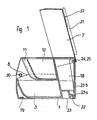
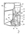
- the cash cassette (FIGS. 1 to 3) essentially consists of a cassette base part 1, the cassette flap 7 and a locking and locking device accommodated in a closed chamber 4 of the cassette base part 1, which together with devices on a base plate will be referred to below with reference to FIGS. 4 to 9 is explained in more detail.
- the molded plastic base part 1 is with two bill compartments 2 and 3 (Fig. 2 and 3) for the horizontal stacking of z. B. DM 50, - and DM 100, notes equipped, which are on both sides of the chamber 4 arranged in the middle.
- Both bill compartments 2 and 3 are each covered by a removable coin insert 5 and 6 in such a way that sufficiently wide and deep openings 8 and 9 are formed towards the front of the operator, which allow the depositing and removal of the banknotes.
- Both coin inserts have three coin trays 11 to 13 or 14 to 16, the middle coin tray 12 or 15 being set back somewhat in order to widen the openings 8 and 9 in the central region for better handling.
- the base part 1 of the cassette has two recesses 22 (FIG. 1) on the lower edge of its rear wall, each of which has an associated hook 23a of a base plate 23.
- the base plate 23 has at its rear edge a perpendicular upward bend 23b against which the base of the cassette is supported with its rear wall in the attached state.
- a vertical hook 23c (FIG. 9) which is used to lock the cassette serves on the base plate 23, which is embedded in a suitable place in front of or to the side of the cash register in the table top of a cash desk gondola or on a sales table or the like.
- Four bearing points 24 to 27 (FIGS.
- the cassette flap 7 is provided on its sides with a stop 30, preferably made of rubber, in order to dampen the impact noise when closing.
- a padded hand rest pad 31 is glued, which is provided with a slot 32 in which received bills can be visibly stored until they are finally deposited after the checkout process has been completed.
- a cranked tab 34 (FIG. 5) is fastened to the cassette flap 7, and a web 36 is formed at the lower end of this by punching out a hole 35.
- this web 36 lies in the fork 38 of a locking lever 39 which is rotatably mounted on a pin 40 and is supported with its edge 41 on a stop surface 43 of a pawl 44.
- the U-shaped pawl 44 is rotatably mounted on a bearing pin 45 and is non-positively pulled into its basic position (FIG. 5) by a tension spring 46 (FIG. 9). By lifting the leg 47 of the pawl 44, it is pivoted clockwise, so that its stop surface 43 releases the edge 41 of the locking lever 39.
- the locking lever 39 pulled by its tension spring 48 and supported by the two torsion springs 28 and 29, can pivot clockwise at the bearing points of the cassette flap 7 until the web 36 of the tab 34 out of the fork 38a (dashed position of the fork 38) slides and the stop edge 49 of a side arm of the locking lever 39 on a rubber roller 50 on a pin 51 comes to rest.
- the cassette flap 7 can open under the action of the torsion springs 28 and 29.
- the switch lever 54 (FIG. 4) which moves the switch pin 56 of the switch 57 via a lever 55 is moved to the left by a pin 53 mounted in the locking lever 39.
- This switch 57 can be used to indicate to a cash register or the like, if any, that the cash cassette is open or closed.
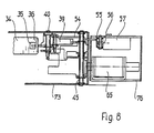
- the above-mentioned lifting of the leg 47 of the pawl 44 takes place by actuating a lock 60 (FIG. 6) arranged on the front edge of the base part 1 of the cassette in a first working position “opening the cassette flap •, by means of which a lock lever 61 (FIGS. 6 and 7 ) is pivoted, the first bend 62 lifts the leg 47 when the lock is turned in the direction of the arrow 63 and thus causes the cassette flap 7 to open.
- the opening of the cassette door 7 can also be triggered by an electrical pulse.
- a magnet 65 (FIG.
- the time in which the pawl 44 is in its open position is also very short. During this time, if the cassette door 7 is in its opening movement by e.g. an unintentional hand load or the like is hindered, a subsequent opening of the cassette flap is no longer possible because the pawl 44 has already moved back to its basic position (FIGS. 4 and 5) and locks the locking lever 39 again. In this case, the checkout process could not be ended.
- an additional pawl 70 (FIG. 9) rotatably mounted on the pin 40 is provided, which holds a leg 72 of the magnetic lever 68 in its open position 72a (dashed line in FIG. 9) with its nose 71. Only shortly before the end of the rotary movement, which the locking lever 39 executes when the cassette flap 7 is opened, does the pin 53 (FIGS. 5 and 9) hit the pawl 70 (FIG. 9, pin 53a) and pivots it a short movement in the clockwise direction until the nose 71 releases the leg 72 of the magnetic lever 68 again. The magnetic lever 68 and the pawl 44 fall back into their basic position and the cassette flap 7 can be closed again.
- the aforementioned vertical hook 23c in the front region of the base plate 23 projects into the chamber 4 or the housing 73 (FIG. 4) when the cash cassette is attached, where it serves as a support for the leg 72 of the magnetic lever 68 (FIG. 9).
- the lock 60 In the basic position of the lock 60 there is a second bend 77 of the lock lever 61 under the hook 23c of the base plate 23, so that the cash box can no longer be removed.
- the second bend 77 is pivoted out of the hook 23c and the cash cassette is unlocked.
- the cash cassette can now be raised on its front side, pulled forward from the rear hooks 23a and lifted off the base plate 23 and placed in a safe for storage, for example.
- the mechanical part of the locking device (FIGS. 4, 6, 8 and 9) with the locking lever 39, the pawl 44, the switch lever 54, the lock 60 with the lock lever 61 and the associated bearing pins 40, 45, 51, 53 and tension springs 46 , 48 is housed in a housing 73 with hooks 74 and two screws 75 in the chamber 4 of the base part 1 of the cassette, while the magnet 65 is fastened in a contact-safe manner in a further housing 76 on the base plate 23, which is fixed in place on the cash desk table of the cash register nacelle or the like.
- the base plate 23 is fastened to the cash desk or the like by a plurality of fastening screws 79. These fastening screws are not accessible when the cash cassette is attached. Disassembly is only possible with the cassette removed. This provides additional theft protection.
Landscapes
- Physics & Mathematics (AREA)
- General Physics & Mathematics (AREA)
- Cash Registers Or Receiving Machines (AREA)
Claims (4)
Priority Applications (2)
| Application Number | Priority Date | Filing Date | Title |
|---|---|---|---|
| EP83109984A EP0136372B1 (fr) | 1983-10-06 | 1983-10-06 | Conteneur d'argent transportable actionné par une caisse enregistreuse |
| AT83109984T ATE22185T1 (de) | 1983-10-06 | 1983-10-06 | Transportable registrierkassengesteuerte geldkassette. |
Applications Claiming Priority (1)
| Application Number | Priority Date | Filing Date | Title |
|---|---|---|---|
| EP83109984A EP0136372B1 (fr) | 1983-10-06 | 1983-10-06 | Conteneur d'argent transportable actionné par une caisse enregistreuse |
Publications (2)
| Publication Number | Publication Date |
|---|---|
| EP0136372A1 EP0136372A1 (fr) | 1985-04-10 |
| EP0136372B1 true EP0136372B1 (fr) | 1986-09-10 |
Family
ID=8190724
Family Applications (1)
| Application Number | Title | Priority Date | Filing Date |
|---|---|---|---|
| EP83109984A Expired EP0136372B1 (fr) | 1983-10-06 | 1983-10-06 | Conteneur d'argent transportable actionné par une caisse enregistreuse |
Country Status (2)
| Country | Link |
|---|---|
| EP (1) | EP0136372B1 (fr) |
| AT (1) | ATE22185T1 (fr) |
Cited By (3)
| Publication number | Priority date | Publication date | Assignee | Title |
|---|---|---|---|---|
| DE4207589C1 (fr) * | 1992-03-10 | 1993-04-01 | Siemens Nixdorf Informationssysteme Ag, 4790 Paderborn, De | |
| DE102005046909B4 (de) * | 2005-09-30 | 2013-04-04 | Anker Systems Gmbh | Vorrichtung zum Verriegeln und Entriegeln des Deckels einer registrierkassengesteuerten Geldkassette |
| DE102015122110A1 (de) | 2015-12-17 | 2017-06-22 | Werner Ulbts | Sicherungssystem und Verfahren zum Öffnen eines Schlosses |
Families Citing this family (6)
| Publication number | Priority date | Publication date | Assignee | Title |
|---|---|---|---|---|
| DE19743691C1 (de) * | 1997-10-02 | 1999-01-14 | Siemens Nixdorf Inf Syst | Einrichtung zum Verriegeln und Entriegeln des Deckels einer registrierkassengesteuerten Geldlade |
| DE19839977A1 (de) * | 1998-09-02 | 2000-03-09 | Siemens Nixdorf Inf Syst | Geldkassettenanordnung |
| EP1067494B1 (fr) * | 1999-07-03 | 2001-08-22 | Anker Systems GmbH | Tiroir-caisse avec déclencheur attaché au boítier |
| DE10255118B4 (de) * | 2002-11-26 | 2006-11-16 | Wincor Nixdorf International Gmbh | Verriegelungseinrichtung zum Verriegeln des Deckels einer Kassenlade an einem Kassenladenunterteil |
| JP4617709B2 (ja) * | 2004-04-28 | 2011-01-26 | セイコーエプソン株式会社 | ロック機構付きケースおよびプリンタ |
| CN104036587B (zh) | 2014-06-30 | 2016-05-11 | 广州广电运通金融电子股份有限公司 | 一种便携鼓式钞箱和一种atm机 |
Family Cites Families (4)
| Publication number | Priority date | Publication date | Assignee | Title |
|---|---|---|---|---|
| WO1979000514A1 (fr) * | 1978-01-18 | 1979-08-09 | Chubb Electronics Ltd | Caisse enregistreuse |
| DE2907801C2 (de) * | 1978-02-28 | 1985-10-31 | Sharp K.K., Osaka | Registrierkasse |
| DE2907643A1 (de) | 1979-02-27 | 1980-08-28 | Nixdorf Computer Ag | Behaelter fuer wertscheine, hartgeld u.dgl. |
| DE3037516A1 (de) | 1980-10-03 | 1982-05-13 | Kaufhof AG, 5000 Köln | Behaelter zur aufnahme und aufbewahrung von geldscheinen |
-
1983
- 1983-10-06 AT AT83109984T patent/ATE22185T1/de not_active IP Right Cessation
- 1983-10-06 EP EP83109984A patent/EP0136372B1/fr not_active Expired
Cited By (4)
| Publication number | Priority date | Publication date | Assignee | Title |
|---|---|---|---|---|
| DE4207589C1 (fr) * | 1992-03-10 | 1993-04-01 | Siemens Nixdorf Informationssysteme Ag, 4790 Paderborn, De | |
| DE102005046909B4 (de) * | 2005-09-30 | 2013-04-04 | Anker Systems Gmbh | Vorrichtung zum Verriegeln und Entriegeln des Deckels einer registrierkassengesteuerten Geldkassette |
| DE102015122110A1 (de) | 2015-12-17 | 2017-06-22 | Werner Ulbts | Sicherungssystem und Verfahren zum Öffnen eines Schlosses |
| DE102015122110B4 (de) | 2015-12-17 | 2018-08-16 | Werner Ulbts | Sicherungssystem und Verfahren zum Öffnen eines Schlosses |
Also Published As
| Publication number | Publication date |
|---|---|
| EP0136372A1 (fr) | 1985-04-10 |
| ATE22185T1 (de) | 1986-09-15 |
Similar Documents
| Publication | Publication Date | Title |
|---|---|---|
| DE69728867T2 (de) | Sichere umrahmung für einen geldautomaten | |
| DE3138732C2 (de) | Automatischer Fernbankschalter | |
| DE69804727T2 (de) | Haltevorrichtung für den Wertscheinprüfer in einem Spielautomaten und Spielautomat, der dieselbe umfasst | |
| DE2949344A1 (de) | Kassette fuer flexible blaetter | |
| EP0136372B1 (fr) | Conteneur d'argent transportable actionné par une caisse enregistreuse | |
| CA2003513A1 (fr) | Dispositif d'interverrouillage de tiroirs | |
| EP0014856B1 (fr) | Conteneur d'argent pour des caisses enregistreuses | |
| DE3227416C1 (de) | Transportable registrierkassengesteuerte Geldkassette | |
| DE102009037459A1 (de) | Behälter zur Aufnahme von Wertscheinen und Verfahren zum Verschließen eines ein Gehäuseteil und einen Deckel umfassenden Behälters zur Aufnahme von Wertscheinen | |
| DE3926132C2 (fr) | ||
| DE1474868B2 (de) | Mittels schluessel und munzen bedienbares tuerschloss | |
| US20060012184A1 (en) | Gaming machine lid/door latch | |
| CH651409A5 (de) | Tresor zur aufnahme von muenzen aus muenz-spielautomaten fuer eine aufstellung in spielhallen, hotels, restaurants, milchbars, imbissstuben und dergleichen. | |
| WO1998059328A1 (fr) | Tiroir-caisse avec insert pivotant pour billets | |
| DE3310656C1 (de) | Transportable registrierkassengesteuerte Geldkassette | |
| EP0099465B1 (fr) | Coffre de dépôt automatique pour billets de banque et monnaies | |
| EP0550546B1 (fr) | Tiroir de caisse enregistreuse | |
| EP0838567B1 (fr) | Serrure électrique de coffre-fort | |
| EP0026745B1 (fr) | Serrure actionnée par des pièces de monnaie | |
| EP0560292B1 (fr) | Dispositif pour le verrouillage et le déverrouillage du couvercle d'un tiroir-caisse actionné par caisse-enregistreuse | |
| DE102005046909B4 (de) | Vorrichtung zum Verriegeln und Entriegeln des Deckels einer registrierkassengesteuerten Geldkassette | |
| EP0977928A1 (fr) | Serrure a commande electrique de casier pour objets de valeur | |
| DE1474868C (de) | Mittels Schlüssel und Münzen bedien bares Türschloß | |
| DE2408131A1 (de) | Geldkassette | |
| DE218980C (fr) |
Legal Events
| Date | Code | Title | Description |
|---|---|---|---|
| PUAI | Public reference made under article 153(3) epc to a published international application that has entered the european phase |
Free format text: ORIGINAL CODE: 0009012 |
|
| AK | Designated contracting states |
Designated state(s): AT CH FR GB IT LI |
|
| EL | Fr: translation of claims filed | ||
| 17P | Request for examination filed |
Effective date: 19850513 |
|
| ITF | It: translation for a ep patent filed | ||
| GRAA | (expected) grant |
Free format text: ORIGINAL CODE: 0009210 |
|
| AK | Designated contracting states |
Kind code of ref document: B1 Designated state(s): AT CH FR GB IT LI |
|
| REF | Corresponds to: |
Ref document number: 22185 Country of ref document: AT Date of ref document: 19860915 Kind code of ref document: T |
|
| ET | Fr: translation filed | ||
| PLBE | No opposition filed within time limit |
Free format text: ORIGINAL CODE: 0009261 |
|
| STAA | Information on the status of an ep patent application or granted ep patent |
Free format text: STATUS: NO OPPOSITION FILED WITHIN TIME LIMIT |
|
| 26N | No opposition filed | ||
| ITTA | It: last paid annual fee | ||
| REG | Reference to a national code |
Ref country code: CH Ref legal event code: NV Representative=s name: PA ALDO ROEMPLER |
|
| REG | Reference to a national code |
Ref country code: CH Ref legal event code: PFA Free format text: ADS - ANKER GMBH TRANSFER- ANKER SYSTEMS GMBH |
|
| PGFP | Annual fee paid to national office [announced via postgrant information from national office to epo] |
Ref country code: AT Payment date: 20010803 Year of fee payment: 19 |
|
| REG | Reference to a national code |
Ref country code: FR Ref legal event code: CD |
|
| PGFP | Annual fee paid to national office [announced via postgrant information from national office to epo] |
Ref country code: GB Payment date: 20011004 Year of fee payment: 19 |
|
| PGFP | Annual fee paid to national office [announced via postgrant information from national office to epo] |
Ref country code: FR Payment date: 20011026 Year of fee payment: 19 |
|
| REG | Reference to a national code |
Ref country code: GB Ref legal event code: IF02 |
|
| PGFP | Annual fee paid to national office [announced via postgrant information from national office to epo] |
Ref country code: CH Payment date: 20020130 Year of fee payment: 19 |
|
| PG25 | Lapsed in a contracting state [announced via postgrant information from national office to epo] |
Ref country code: GB Free format text: LAPSE BECAUSE OF NON-PAYMENT OF DUE FEES Effective date: 20021006 Ref country code: AT Free format text: LAPSE BECAUSE OF NON-PAYMENT OF DUE FEES Effective date: 20021006 |
|
| PG25 | Lapsed in a contracting state [announced via postgrant information from national office to epo] |
Ref country code: LI Free format text: LAPSE BECAUSE OF NON-PAYMENT OF DUE FEES Effective date: 20021031 Ref country code: CH Free format text: LAPSE BECAUSE OF NON-PAYMENT OF DUE FEES Effective date: 20021031 |
|
| GBPC | Gb: european patent ceased through non-payment of renewal fee |
Effective date: 20021006 |
|
| REG | Reference to a national code |
Ref country code: CH Ref legal event code: PL |
|
| PG25 | Lapsed in a contracting state [announced via postgrant information from national office to epo] |
Ref country code: FR Free format text: LAPSE BECAUSE OF NON-PAYMENT OF DUE FEES Effective date: 20030630 |
|
| REG | Reference to a national code |
Ref country code: FR Ref legal event code: ST |