EP0136403B1 - Vorrichtung zum Einführen einer Warenbahn in eine Behandlungsmaschine - Google Patents
Vorrichtung zum Einführen einer Warenbahn in eine Behandlungsmaschine Download PDFInfo
- Publication number
- EP0136403B1 EP0136403B1 EP84106688A EP84106688A EP0136403B1 EP 0136403 B1 EP0136403 B1 EP 0136403B1 EP 84106688 A EP84106688 A EP 84106688A EP 84106688 A EP84106688 A EP 84106688A EP 0136403 B1 EP0136403 B1 EP 0136403B1
- Authority
- EP
- European Patent Office
- Prior art keywords
- edge strip
- web
- edge
- knife
- pair
- Prior art date
- Legal status (The legal status is an assumption and is not a legal conclusion. Google has not performed a legal analysis and makes no representation as to the accuracy of the status listed.)
- Expired
Links
- 239000000463 material Substances 0.000 claims abstract description 6
- 230000037431 insertion Effects 0.000 claims 1
- 238000003780 insertion Methods 0.000 claims 1
- 238000007664 blowing Methods 0.000 description 1
- 239000011111 cardboard Substances 0.000 description 1
- 238000000034 method Methods 0.000 description 1
- 239000011087 paperboard Substances 0.000 description 1
- 238000000926 separation method Methods 0.000 description 1
Images
Classifications
-
- B—PERFORMING OPERATIONS; TRANSPORTING
- B26—HAND CUTTING TOOLS; CUTTING; SEVERING
- B26D—CUTTING; DETAILS COMMON TO MACHINES FOR PERFORATING, PUNCHING, CUTTING-OUT, STAMPING-OUT OR SEVERING
- B26D7/00—Details of apparatus for cutting, cutting-out, stamping-out, punching, perforating, or severing by means other than cutting
- B26D7/18—Means for removing cut-out material or waste
-
- Y—GENERAL TAGGING OF NEW TECHNOLOGICAL DEVELOPMENTS; GENERAL TAGGING OF CROSS-SECTIONAL TECHNOLOGIES SPANNING OVER SEVERAL SECTIONS OF THE IPC; TECHNICAL SUBJECTS COVERED BY FORMER USPC CROSS-REFERENCE ART COLLECTIONS [XRACs] AND DIGESTS
- Y10—TECHNICAL SUBJECTS COVERED BY FORMER USPC
- Y10T—TECHNICAL SUBJECTS COVERED BY FORMER US CLASSIFICATION
- Y10T83/00—Cutting
- Y10T83/202—With product handling means
- Y10T83/2074—Including means to divert one portion of product from another
- Y10T83/2083—Deflecting guide
-
- Y—GENERAL TAGGING OF NEW TECHNOLOGICAL DEVELOPMENTS; GENERAL TAGGING OF CROSS-SECTIONAL TECHNOLOGIES SPANNING OVER SEVERAL SECTIONS OF THE IPC; TECHNICAL SUBJECTS COVERED BY FORMER USPC CROSS-REFERENCE ART COLLECTIONS [XRACs] AND DIGESTS
- Y10—TECHNICAL SUBJECTS COVERED BY FORMER USPC
- Y10T—TECHNICAL SUBJECTS COVERED BY FORMER US CLASSIFICATION
- Y10T83/00—Cutting
- Y10T83/202—With product handling means
- Y10T83/2092—Means to move, guide, or permit free fall or flight of product
- Y10T83/2209—Guide
- Y10T83/2216—Inclined conduit, chute or plane
-
- Y—GENERAL TAGGING OF NEW TECHNOLOGICAL DEVELOPMENTS; GENERAL TAGGING OF CROSS-SECTIONAL TECHNOLOGIES SPANNING OVER SEVERAL SECTIONS OF THE IPC; TECHNICAL SUBJECTS COVERED BY FORMER USPC CROSS-REFERENCE ART COLLECTIONS [XRACs] AND DIGESTS
- Y10—TECHNICAL SUBJECTS COVERED BY FORMER USPC
- Y10T—TECHNICAL SUBJECTS COVERED BY FORMER US CLASSIFICATION
- Y10T83/00—Cutting
- Y10T83/546—Interrelated tool actuating and work guide moving means
-
- Y—GENERAL TAGGING OF NEW TECHNOLOGICAL DEVELOPMENTS; GENERAL TAGGING OF CROSS-SECTIONAL TECHNOLOGIES SPANNING OVER SEVERAL SECTIONS OF THE IPC; TECHNICAL SUBJECTS COVERED BY FORMER USPC CROSS-REFERENCE ART COLLECTIONS [XRACs] AND DIGESTS
- Y10—TECHNICAL SUBJECTS COVERED BY FORMER USPC
- Y10T—TECHNICAL SUBJECTS COVERED BY FORMER US CLASSIFICATION
- Y10T83/00—Cutting
- Y10T83/647—With means to convey work relative to tool station
- Y10T83/6476—Including means to move work from one tool station to another
- Y10T83/6489—Slitter station
- Y10T83/6491—And transverse cutter station
Definitions
- the invention relates to a device for inserting a web into a treatment machine, which comprises a separating knife for separating at least one edge strip and means for guiding this edge strip.
- Such a device is e.g. known from DE-OS 3218306.
- the severed edge strip is blown onto guide plates by blowing with compressed air flowing from nozzle openings, which guide it then to the desired treatment machine. If the edge strip is inserted into the treatment machine, the cutting off of the edge strip is interrupted and the full width of the web is then drawn into the treatment machine into which the edge strip was already threaded.
- the invention is based on the object of specifying means which enable an exact and trouble-free guiding of the edge strip separated from the material web for the introduction thereof into any subsequent treatment machines.
- the device according to the invention enables the detached edge strip of a web of material to be reliably detected and exactly continued in any subsequent treatment machines.
- This process can be controlled fully automatically.
- the entire device is pivoted outwards about a vertical axis, so that the edge strip runs away from the rest of the material web. Both the material web and the separated edge strips run into the pulper.
- the cross section knife By actuating the cross section knife, the edge strip is cut off, and the new beginning of the edge strip formed thereby is conveyed by the guide surfaces on the cross section knife, which are preferably adapted to the radius of the one roller of the pressure roller pair, onto a transfer table or into a cable shear which cuts it into the desired position guide the subsequent treatment machine.
- the device can also be expedient to mount the device so that it can be pivoted about a horizontal axis, so that the edge strip can be deflected upwards or downwards.
- the edge strip 2 is pivoted outward into the transfer position into the transfer position (FIG. 2) by actuating the cylinder / piston unit 8 about the vertical axes 9.
- the separation process is initiated in the horizontal direction via a prestressed compressed air cylinder 10, which moves the cross-section knife 11 in the direction of the edge strip 2.
- the cutting speed of the knife 11 is almost matched to the speed of the web 3.
- the profile of the knife 11 is adapted to the roll 5, so that the direction of the run is specified at the beginning of the cut edge strip 2.
- the edge strip 2 is deflected from the vertical into the horizontal and is guided on the guide table 13 to the cable shear 14, which further promotes it.
- the entire device can be used to achieve certain shooting positions, e.g. Swivel up or down about an axis via bellows cylinders to other angular positions.
Landscapes
- Life Sciences & Earth Sciences (AREA)
- Forests & Forestry (AREA)
- Engineering & Computer Science (AREA)
- Mechanical Engineering (AREA)
- Separation, Sorting, Adjustment, Or Bending Of Sheets To Be Conveyed (AREA)
- Paper (AREA)
- Replacement Of Web Rolls (AREA)
- Making Paper Articles (AREA)
- Treatment Of Fiber Materials (AREA)
- Electron Beam Exposure (AREA)
- Display Devices Of Pinball Game Machines (AREA)
- Control And Other Processes For Unpacking Of Materials (AREA)
Description
- Die Erfindung betrifft eine Vorrichtung zum Einführen einer Warenbahn in eine Behandlungsmaschine, die ein Trennmesser zum Abtrennen mindestens eines Randstreifens und Mittel zum Führen dieses Randstreifens umfasst.
- Eine solche Vorrichtung ist z.B. aus der DE-OS 3218306 bekannt. Bei dieser bekannten Vorrichtung wird der abgetrennte Randstreifen durch Anblasen mit aus Düsenöffnungen strömender Pressluft auf Leitbleche geblasen, die ihn dann zu der gewünschten Behandlungsmaschine führen. Ist der Randstreifen in die Behandlungsmaschine eingeführt, wird das Abtrennen des Randstreifens unterbrochen und die Bahn wird dann in voller Breite in die Behandlungsmaschine, in die der Randstreifen bereits eingefädelt war, eingezogen.
- Das Arbeiten mit Pressluft zum Führen des Randstreifens bringt einige Nachteile mit sich. Eine exakte Führung des Randstreifens ist auch schwierig, da er seitlich aus seiner ursprünglichen Laufrichtung herausgeführt werden muss, damit er seitlich an nachfolgenden Behandlungsmaschinen, durch die die Bahn hindurchgeführt werden soll, vorbeigeführt werden kann.
- Der Erfindung liegt nun die Aufgabe zugrunde, Mittel anzugeben, die ein exaktes und störungsfreies Führen des von der Warenbahn abgetrennten Randstreifens zum Einführen desselben in beliebige nachfolgende Behandlungsmaschinen ermöglicht.
- Zur Lösung dieser Aufgabe wird erfindungsgemäss eine gattungsgemässe Vorrichtung mit den im Anspruch 1 gekennzeichneten Merkmalen vorgeschlagen. Bevorzugte Ausgestaltungen sind in den Unteransprüchen gekennzeichnet.
- Die erfindungsgemässe Vorrichtung ermöglicht ein sicheres Erfassen und genaues Weiterführen des abgetrennten Randstreifens einer Warenbahn in beliebige nachfolgende Behandlungsmaschinen. Dabei kann dieser Vorgang vollautomatisch gesteuert werden. Nach dem Erfassen des abgetrennten Randstreifens durch das Druckrollenpaar wird die gesamte Vorrichtung um eine vertikale Achse nach aussen geschwenkt, so dass der Randstreifen von dem Rest der Warenbahn wegläuft. Beide, Warenbahn und abgetrennter Randstreifen, laufen dabei in den Pulper. Durch Betätigen des Querteilmessers wird der Randstreifen abgeschnitten, und der dabei gebildete neue Anfang des Randstreifens wird durch die Leitflächen am Querteilmesser, die bevorzugt dem Radius der einen Rolle des Druckrollenpaares angepasst sind, auf einen Überführungstisch oder in eine Seilschere befördert, die ihn in die gewünschte nachfolgende Behandlungsmaschine führen.
- Zum besseren Vorbeiführen an nachfolgenden Einrichtungen kann es auch zweckmässig sein, die Vorrichtung um eine horizontale Achse schwenkbar zu lagern, damit der Randstreifen nach oben oder unten abgelenkt werden kann.
- Anhand des in der Zeichnung dargestellten Ausführungsbeispiels wird die Erfindung näher erläutert.
- Es zeigen:
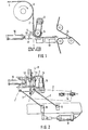
- Fig. 1 die Vorrichtung in Seitenansicht, und
- Fig. 2 in Draufsicht.
- Der von einer Walze 1 frei ablaufende Randstreifen 2 der Warenbahn 3, z. B. Papier oder Karton, wird von einem Druckrollenpaar 4, 5 geführt und hierbei in seiner Bewegung beruhigt. Die eine Rolle 5 des Druckrollenpaares wird über einen Motor 6 angetrieben. Die andere Rolle 4 ist gummiert und wird an die Rolle 5 gedrückt, so dass der ablaufende Randstreifen 2 gehalten und gleichzeitig spannungslos geführt wird.
- Z.B. über ein Parallelogrammgestänge 7 wird der Randstreifen 2 durch Betätigen der Zylinder-Kolbeneinheit 8 um die vertikalen Achsen 9 in die Übergabeposition nach aussen in die strichpunktiert eingezeichnete Stellung (Fig. 2) geschwenkt. Unmittelbar danach wird der Trennvorgang über einen vorgespannten Pressluftzylinder 10 in horizontaler Richtung eingeleitet, der das Querteilmesser 11 in Richtung auf den Randstreifen 2 zu bewegt. Die Schnittgeschwindigkeit des Messers 11 wird hierbei der Geschwindigkeit der Warenbahn 3 nahezu angeglichen. Das Profil des Messers 11 ist der Rolle 5 angepasst, so dass dem Anfang des geschnittenen Randstreifens 2 die Ablaufrichtung vorgegeben wird. Durch den zwischen den Leitflächen 12 am vorgeschobenen Messer 11 (gestrichelt angedeutet) und der Rolle 5 gebildeten Spalt wird der Randstreifen 2 aus der Vertikalen in die Horizontale umgelenkt und auf dem Führungstisch 13 zu der Seilschere 14 geleitet, die ihn weiterfördert.
- Um bestimmte Einschiesspositionen zu erreichen, lässt sich in Sonderfällen die Gesamtvorrichtung z.B. über Balgzylinder um eine Achse in andere Winkelstellungen hoch- oder herunterschwenken.
Claims (3)
Priority Applications (1)
| Application Number | Priority Date | Filing Date | Title |
|---|---|---|---|
| AT84106688T ATE29702T1 (de) | 1983-08-19 | 1984-06-12 | Vorrichtung zum einfuehren einer warenbahn in eine behandlungsmaschine. |
Applications Claiming Priority (2)
| Application Number | Priority Date | Filing Date | Title |
|---|---|---|---|
| DE3329987A DE3329987C1 (de) | 1983-08-19 | 1983-08-19 | Vorrichtung zum Einfuehren einer Warenbahn in eine Behandlungsmaschine |
| DE3329987 | 1983-08-19 |
Publications (2)
| Publication Number | Publication Date |
|---|---|
| EP0136403A1 EP0136403A1 (de) | 1985-04-10 |
| EP0136403B1 true EP0136403B1 (de) | 1987-09-16 |
Family
ID=6206962
Family Applications (1)
| Application Number | Title | Priority Date | Filing Date |
|---|---|---|---|
| EP84106688A Expired EP0136403B1 (de) | 1983-08-19 | 1984-06-12 | Vorrichtung zum Einführen einer Warenbahn in eine Behandlungsmaschine |
Country Status (5)
| Country | Link |
|---|---|
| US (1) | US4611518A (de) |
| EP (1) | EP0136403B1 (de) |
| AT (1) | ATE29702T1 (de) |
| DE (1) | DE3329987C1 (de) |
| FI (1) | FI77396C (de) |
Families Citing this family (18)
| Publication number | Priority date | Publication date | Assignee | Title |
|---|---|---|---|---|
| FI74315C (fi) * | 1986-04-18 | 1988-01-11 | Tampella Oy Ab | Anordning foer kapning och stypning av ett kantband vid ledandet av en pappers- eller kartongbana. |
| US5205504A (en) * | 1989-11-10 | 1993-04-27 | Mitsubishi Jukogyo Kabushiki Kaisha | Auto-threading apparatus |
| EP0427234B1 (de) * | 1989-11-10 | 1995-02-01 | Mitsubishi Jukogyo Kabushiki Kaisha | Verfahren und Vorrichtung zum automatischen Einziehen eines Films |
| FR2656289B1 (de) * | 1989-12-27 | 1993-02-19 | Sagem | |
| US5516221A (en) * | 1993-12-03 | 1996-05-14 | Lake; Richard L. | Quick-attaching edge trimmer for pin-feed paper systems |
| JP3560676B2 (ja) * | 1995-03-23 | 2004-09-02 | 富士写真フイルム株式会社 | 裁断耳自動処理装置 |
| US5622601A (en) * | 1995-09-19 | 1997-04-22 | Beloit Technologies, Inc. | Method and apparatus for effecting a clipped tail in a traveling paper web |
| DE19713540A1 (de) * | 1997-04-01 | 1998-10-08 | Voith Sulzer Papiermasch Gmbh | Streifenabschlag- und Überführeinrichtung sowie Verfahren zum Abschlagen und Überführen eines Einfädelstreifens |
| EP0937672A1 (de) * | 1998-02-20 | 1999-08-25 | E.I. Du Pont De Nemours And Company | Vorrichtung und Verfahren zum Schneiden einer zum Zuführen und Einbringen der Bahn in einer Produktionseinheit |
| DE10033456A1 (de) * | 2000-07-10 | 2002-01-24 | Voith Paper Patent Gmbh | Verfahren sowie Vorrichtung zum Überführen einer flexiblen Materialbahn |
| SE518970C2 (sv) * | 2001-04-26 | 2002-12-10 | Flaekt Ab | Förfarande och anordning vid spetsdragning av ett banformigt material |
| DE102005018767A1 (de) * | 2005-04-22 | 2006-10-26 | Voith Patent Gmbh | Schneideinrichtung |
| DE102005018769A1 (de) * | 2005-04-22 | 2006-10-26 | Voith Patent Gmbh | Schneideinrichtung |
| SE529703C8 (sv) * | 2006-03-23 | 2007-11-27 | Andritz Tech & Asset Man Gmbh | Sätt och anordning för överföring av en spets av en cellulosabaserad fibrös bana |
| WO2012127940A1 (ja) * | 2011-03-24 | 2012-09-27 | デュプロ精工株式会社 | 用紙加工装置の制御方法 |
| US9808951B2 (en) * | 2015-04-14 | 2017-11-07 | Braner Usa, Inc. | Scrap winder |
| CN108908471B (zh) * | 2018-07-26 | 2020-05-05 | 务川县天门山农业开发有限公司 | 一种白芨生产加工装置 |
| ES3036086T3 (en) * | 2019-12-18 | 2025-09-12 | Heidelberger Druckmasch Ag | Method for operating a flat bed press for cutting out |
Family Cites Families (9)
| Publication number | Priority date | Publication date | Assignee | Title |
|---|---|---|---|---|
| DE7234602U (de) * | 1975-03-13 | Stahlwerke Peine Salzgitter Ag | Vorrichtung zum Besäumen überstehender Beschichtungsränder, insbesondere bei der Herstellung kunststoffbeschichteter Bleche | |
| US2507144A (en) * | 1948-04-02 | 1950-05-09 | Peter J Christman | Web winding machine |
| US2512900A (en) * | 1948-04-21 | 1950-06-27 | Edwin M Kwitek | Paper winding machine sealing mechanism |
| US3103843A (en) * | 1958-07-02 | 1963-09-17 | Donnelley & Sons Co | Web feed apparatus for a case forming machine for books |
| GB1372653A (en) * | 1973-04-30 | 1974-11-06 | Reed International Ltd | Web feeding apparatus |
| JPS54108998A (en) * | 1978-02-14 | 1979-08-27 | Hashimoto Denki Co Ltd | Continuous cutter of veneer |
| DE3115688C2 (de) * | 1981-04-18 | 1983-11-10 | Herbert Ing.(Grad.) 4358 Haltern Gawarecki | Vorrichtung zum Trennen von aus einer Materialbahn zu lösenden Nutzen und Abfällen |
| FI62695C (fi) * | 1981-05-15 | 1983-02-10 | Valmet Oy | Anordning i en pappersmaskin foer kapning och styrning av en pappersbanans kantremsa |
| US4444362A (en) * | 1982-03-05 | 1984-04-24 | Beloit Corporation | Apparatus and method for starting successive leading ends on travelling web in a winder |
-
1983
- 1983-08-19 DE DE3329987A patent/DE3329987C1/de not_active Expired
-
1984
- 1984-06-12 AT AT84106688T patent/ATE29702T1/de not_active IP Right Cessation
- 1984-06-12 EP EP84106688A patent/EP0136403B1/de not_active Expired
- 1984-07-18 FI FI842891A patent/FI77396C/fi not_active IP Right Cessation
- 1984-08-20 US US06/642,240 patent/US4611518A/en not_active Expired - Fee Related
Also Published As
| Publication number | Publication date |
|---|---|
| US4611518A (en) | 1986-09-16 |
| DE3329987C1 (de) | 1984-12-13 |
| FI77396C (fi) | 1989-03-10 |
| FI77396B (fi) | 1988-11-30 |
| EP0136403A1 (de) | 1985-04-10 |
| ATE29702T1 (de) | 1987-10-15 |
| FI842891A0 (fi) | 1984-07-18 |
| FI842891A7 (fi) | 1985-02-20 |
Similar Documents
| Publication | Publication Date | Title |
|---|---|---|
| EP1110724B1 (de) | Vorrichtung zum Einziehen einer Papierbahn | |
| DE69612392T2 (de) | Trennvorrichtung für trägerbandlose etiketten | |
| EP0136403A1 (de) | Vorrichtung zum Einführen einer Warenbahn in eine Behandlungsmaschine | |
| DE3010808C2 (de) | Beschnittführung für eine Streifenschneide-/Anritzmaschine | |
| EP0827931B1 (de) | Vorrichtung und Verfahren zum dynamischen Führen von flachen produkten | |
| DE69911714T2 (de) | Beutel-Wickelmaschine und Verfahren dazu | |
| EP0031515A1 (de) | Vorrichtung zum Herstellen von Packungs-Zuschnitten durch Abtrennen von einer fortlaufenden Bahn | |
| DE3229765A1 (de) | Vorrichtung zum entfernen einer banderole von einem blattbuendel | |
| EP1245729A1 (de) | Verfahren und Vorrichtung zum Überführen einer Bahn | |
| DE2812579C2 (de) | Vorrichtung zum Einführen des freien Endes einer kontinuierlich geförderten Kunststoffbahn in eine Streck- und Fixierstation | |
| DE3002092C2 (de) | Vorrichtung zum Zuführen von bandförmigem Verpackungsmaterial | |
| DE1511715B1 (de) | Vorrichtung zum Zufuehren eines Bogens Verpackungsmaterials zu einem Stapel,Paket oder anderen Gegenstand | |
| DE2409492A1 (de) | Vorrichtung zum ausziehen und zum einschieben von in laengsrichtung gefoerderten wellpappbahnen in querschneidervorrichtungen | |
| DE19931797C1 (de) | Verfahren und Vorrichtung zum Kürzen der Fahne im Anschluß an einen fliegenden Rollenwechsel | |
| DE102012206848B4 (de) | Entnahmevorrichtung zur Entnahme von Flachteilen | |
| DE1461203A1 (de) | Schneid- und Foerdervorrichtung fuer Bogenmaterial | |
| EP0227896B1 (de) | Vorzugseinheit für Papier- und/oder Folienschlauchmaschine | |
| EP1424441B1 (de) | Verfahren und Vorrichtung zum Überführen einer Papierbahn | |
| DE3123136A1 (de) | "bandagentrenneinrichtung" | |
| CH692730A5 (de) | Einrichtung zum Fälzeln oder Hinterkleben von Buchblocks. | |
| DE3226627C2 (de) | Vorrichtung zum Erfassen und Transportieren von einen Rotationsquerschneider verlassenden Bogen | |
| DE10146538A1 (de) | Verfahren und Vorrichtung zum Überführen einer Papierbahn | |
| DE19605339C1 (de) | Vorrichtung zum Schneiden einer Endlospapierbahn | |
| DE2407848A1 (de) | Verfahren zum einebnen und ebenflaechigen weiterfuehren von einer oder mehreren in papierverarbeitungsmaschinen freischwebend gefuehrten materialbahnen | |
| DE3727358A1 (de) | Verfahren und vorrichtung zur stabilisierung von extrem duennem packmittel |
Legal Events
| Date | Code | Title | Description |
|---|---|---|---|
| PUAI | Public reference made under article 153(3) epc to a published international application that has entered the european phase |
Free format text: ORIGINAL CODE: 0009012 |
|
| AK | Designated contracting states |
Designated state(s): AT CH GB IT LI SE |
|
| RTI1 | Title (correction) | ||
| RAP1 | Party data changed (applicant data changed or rights of an application transferred) |
Owner name: JAGENBERG AG |
|
| 17P | Request for examination filed |
Effective date: 19850912 |
|
| 17Q | First examination report despatched |
Effective date: 19860224 |
|
| GRAA | (expected) grant |
Free format text: ORIGINAL CODE: 0009210 |
|
| AK | Designated contracting states |
Kind code of ref document: B1 Designated state(s): AT CH GB IT LI SE |
|
| REF | Corresponds to: |
Ref document number: 29702 Country of ref document: AT Date of ref document: 19871015 Kind code of ref document: T |
|
| GBT | Gb: translation of ep patent filed (gb section 77(6)(a)/1977) | ||
| ITF | It: translation for a ep patent filed | ||
| RAP4 | Party data changed (patent owner data changed or rights of a patent transferred) |
Owner name: JAGENBERG AKTIENGESELLSCHAFT |
|
| PLBE | No opposition filed within time limit |
Free format text: ORIGINAL CODE: 0009261 |
|
| STAA | Information on the status of an ep patent application or granted ep patent |
Free format text: STATUS: NO OPPOSITION FILED WITHIN TIME LIMIT |
|
| 26N | No opposition filed | ||
| PGFP | Annual fee paid to national office [announced via postgrant information from national office to epo] |
Ref country code: CH Payment date: 19930512 Year of fee payment: 10 |
|
| ITTA | It: last paid annual fee | ||
| PG25 | Lapsed in a contracting state [announced via postgrant information from national office to epo] |
Ref country code: LI Effective date: 19940630 Ref country code: CH Effective date: 19940630 |
|
| EAL | Se: european patent in force in sweden |
Ref document number: 84106688.9 |
|
| REG | Reference to a national code |
Ref country code: CH Ref legal event code: PL |
|
| PGFP | Annual fee paid to national office [announced via postgrant information from national office to epo] |
Ref country code: GB Payment date: 19950515 Year of fee payment: 12 |
|
| PGFP | Annual fee paid to national office [announced via postgrant information from national office to epo] |
Ref country code: AT Payment date: 19950520 Year of fee payment: 12 |
|
| PGFP | Annual fee paid to national office [announced via postgrant information from national office to epo] |
Ref country code: SE Payment date: 19950529 Year of fee payment: 12 |
|
| PG25 | Lapsed in a contracting state [announced via postgrant information from national office to epo] |
Ref country code: GB Effective date: 19960612 Ref country code: AT Effective date: 19960612 |
|
| PG25 | Lapsed in a contracting state [announced via postgrant information from national office to epo] |
Ref country code: SE Effective date: 19960613 |
|
| GBPC | Gb: european patent ceased through non-payment of renewal fee |
Effective date: 19960612 |
|
| EUG | Se: european patent has lapsed |
Ref document number: 84106688.9 |