EP0136426A2 - Ruban de mesurage - Google Patents
Ruban de mesurage Download PDFInfo
- Publication number
- EP0136426A2 EP0136426A2 EP84108250A EP84108250A EP0136426A2 EP 0136426 A2 EP0136426 A2 EP 0136426A2 EP 84108250 A EP84108250 A EP 84108250A EP 84108250 A EP84108250 A EP 84108250A EP 0136426 A2 EP0136426 A2 EP 0136426A2
- Authority
- EP
- European Patent Office
- Prior art keywords
- spring
- cover
- tape
- disk
- tne
- Prior art date
- Legal status (The legal status is an assumption and is not a legal conclusion. Google has not performed a legal analysis and makes no representation as to the accuracy of the status listed.)
- Withdrawn
Links
Images



Classifications
-
- G—PHYSICS
- G01—MEASURING; TESTING
- G01B—MEASURING LENGTH, THICKNESS OR SIMILAR LINEAR DIMENSIONS; MEASURING ANGLES; MEASURING AREAS; MEASURING IRREGULARITIES OF SURFACES OR CONTOURS
- G01B3/00—Measuring instruments characterised by the use of mechanical techniques
- G01B3/10—Measuring tapes
- G01B3/1005—Means for controlling winding or unwinding of tapes
-
- G—PHYSICS
- G01—MEASURING; TESTING
- G01B—MEASURING LENGTH, THICKNESS OR SIMILAR LINEAR DIMENSIONS; MEASURING ANGLES; MEASURING AREAS; MEASURING IRREGULARITIES OF SURFACES OR CONTOURS
- G01B3/00—Measuring instruments characterised by the use of mechanical techniques
- G01B3/10—Measuring tapes
- G01B3/1041—Measuring tapes characterised by casings
-
- G—PHYSICS
- G01—MEASURING; TESTING
- G01B—MEASURING LENGTH, THICKNESS OR SIMILAR LINEAR DIMENSIONS; MEASURING ANGLES; MEASURING AREAS; MEASURING IRREGULARITIES OF SURFACES OR CONTOURS
- G01B3/00—Measuring instruments characterised by the use of mechanical techniques
- G01B3/10—Measuring tapes
- G01B3/1041—Measuring tapes characterised by casings
- G01B3/1043—Details of internal structure thereof, e.g. means for coupling separately moulded casing halves
-
- G—PHYSICS
- G01—MEASURING; TESTING
- G01B—MEASURING LENGTH, THICKNESS OR SIMILAR LINEAR DIMENSIONS; MEASURING ANGLES; MEASURING AREAS; MEASURING IRREGULARITIES OF SURFACES OR CONTOURS
- G01B3/00—Measuring instruments characterised by the use of mechanical techniques
- G01B3/10—Measuring tapes
- G01B3/1041—Measuring tapes characterised by casings
- G01B3/1046—Details of external structure thereof, e.g. shapes for ensuring firmer hold
-
- G—PHYSICS
- G01—MEASURING; TESTING
- G01B—MEASURING LENGTH, THICKNESS OR SIMILAR LINEAR DIMENSIONS; MEASURING ANGLES; MEASURING AREAS; MEASURING IRREGULARITIES OF SURFACES OR CONTOURS
- G01B3/00—Measuring instruments characterised by the use of mechanical techniques
- G01B3/10—Measuring tapes
- G01B3/1005—Means for controlling winding or unwinding of tapes
- G01B2003/1023—Winding mechanisms
- G01B2003/103—Winding mechanisms operated by springs
-
- G—PHYSICS
- G01—MEASURING; TESTING
- G01B—MEASURING LENGTH, THICKNESS OR SIMILAR LINEAR DIMENSIONS; MEASURING ANGLES; MEASURING AREAS; MEASURING IRREGULARITIES OF SURFACES OR CONTOURS
- G01B3/00—Measuring instruments characterised by the use of mechanical techniques
- G01B3/10—Measuring tapes
- G01B3/1005—Means for controlling winding or unwinding of tapes
- G01B2003/1033—Means for activating the locking, braking or releasing of the tape, e.g. buttons
- G01B2003/1035—Means for activating the locking, braking or releasing of the tape, e.g. buttons by pivotal operation
Definitions
- the present invention relates to a gearless tape measure having an adjustable tension and a brake.
- United States Patent 3,054,573 discloses an improved tape measure which eliminates projecting parts, such as handles by using gears within the tape to augment the spring tension.
- the spring and driving gears are separated in sealed compartments.
- this gear-type tape measure still presents serious problems to economical construction and efficient use.
- the gears of the tape measure can foul with dirt during logging and other uses of the tape measure.
- Modern improvements in spring metal have eliminated the necessity of using a gear system to provide necessary spring tensioning force to retract even long tapes.
- the advent of the modern springs has allowed improvements to the tape measure, especially the removal of gears, which are incorporated in the improved tape measure of this invention.
- the tape measure includes a generally disk-shaped dust cover having a centrally disposed hub which projects upwardly substantially perpendicular to the cover from one side of the cover.
- a revolvable, spring-retaining disk which has a diameter slighlty less than the diameter of the cover, is seated on the cover around the hub and nas a spring-retaining well whose outer periphery is defined by an upraised wall.
- the wall is substantially concentric with the disk and has at least one slot to allow passage of the spring or tape through the wall.
- a spiral spring is retained within the well of the spring-retaining disk.
- One end of the spring is affixed to the hub, preferably by placing a tang of the spring in a slot of the hub.
- the other end of the spring is attached to a graduated tape.
- the tape passes through the slot in the wall of the spring-retaining disk and is wound about the outer periphery of the wall. Thus, the tape is exposed and the tape measure is "open-faced.”
- the slotted wall protects the spring from fouling by dirt.
- an input tensioning assembly is incorporated into the improved tape measure.
- the input tensioning assembly includes a revolvable input disk which has a diameter slightly less than the diameter of the cover and which is seated atop the wall of the spring-retaining disk about the hub.
- the spring-retaining disk When the input disk is compressed tightly against the top of the wall of the spring-retaining disk and is revolved, the spring-retaining disk also turns. Because the spring is constrained in the hub, which is fixed, the spring either tightens or loosens as the disk turns relative to the hub, since it winds or unwinds about the hub.
- a generally disK-snaped cover plate which has a diameter slightly less than the diameter of the cover, rests atop the input disk and allows revolution of the input disk and spring-retaining disk during use of the tape while being compressible down upon the input disk so that the tension of the spring may be adjusted. That is, the cover plate is capable of turning both the input disk and the spring-retaining disk when it is compressed tightly against the input disk and is turned relative to the cover.
- a pair of compression lock rings sand- wicn the edge of the cover plate. Eacn lock ring has an outside diameter substantially equal to the diameter of tne bottom cover.
- the lock rings When compressed against the top cover plate, the lock rings hold the cover plate and Keep it from revolving. when loosened, tne lock rings allow the cover plate to be pressed against the input disk and turned to simultaneously turn tne input disK and spring-retaining disk.
- Fasteners join the two lock rings and bottom cover in substantially parallel, axially aligned positions. These fasteners allow holding of the cover plate tightly between the lock rings during normal use of the tape measure, but allow the cover plate to be compressed against the input disk when desired. After a tension adjustment, the fasteners allow refastening of the lock rings to hold the cover plate and to allow normal use of the tape measure.
- the fasteners include a plurality of collars positionable at predetermined locations around the periphery of the cover and a plurality of screws to fasten the lock rings or the cover to the collars, depending upon the side of the tape measure being considered.
- tne tape measure nas a generally disk-shaped dust cover which nas a central nub-receiving well.
- a revolvaole spring-retaining disk and an input disk overlie tne cover.
- a cover plate completes the tape measure ana includes a centrally disposed hub which projects downwardly substantially perpendicular to the cover plate. The spring is attached to the hub. As previously described, the cover plate has a diameter slightly less than the diameter of the cover and is retained in locking rings. When tne rings are loosened, the cover plate may be turned to tighten or to loosen the spring.
- a slide ridge may be aaaed to the spring-retaining disk to abut the cover and to reduce the frictional surface area of contact between the spring-retaining disk and the cover.
- This slide ridge ensures that the spring-retaining disk is easier to revolve about the hub.
- the input disk may include an inset groove to mate with the top of the wall so that the wall revolves in the groove in the input disk when the tape measure is assembled. This groove helps to limit wobble of the spring-retaining disk.
- the input disk may also include a plurality of stabilizers which project upwardly from the input disk between its top and the cover plate to reduce wobble of the input disk.
- the tape measure may also include a friction brake which will hold the tape when it is pulled from the spring-retaining disk.
- the brake bears against the tape to counter the spring tension tnat seeks to automatically retract the tape.
- a g earless, open-faced, direct-drive, spring-rewound tape measure is easily constructea and is a decidea improvement over existing tape measures.
- Tne entire tape measure may be mace from aluminum or plastic and, therefore, may be much lighter and less expensive.
- the tape measure is thinner than earlier tape measures because gears or handles are eliminated through use of the improved spiral spring.
- a simple and quick means is employed to adjust the spring tension without use of gears.
- the tape measure is less susceptible to fouling by dirt and is less susceptible to damage even when placed in heavy use.
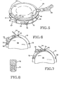
- a gearless, open-faced, direct-drive, spring-rewound tape measure lU has a cover 12 as a base. Positioned centrally within the disk-shaped cover 12 is a hub 14 having a slot 16 which is capable of receiving the tang of a spiral spring.
- the hub 14 projects upwardly substantially perpendicular to the cover 12 from one side of the cover 12.
- the hub 14 attaches to the cover 12 with a wedge and stake assembly (as best shown in Figure 2).
- a spring-retaining disk 18 seats on the cover 12 around the hub 14. Tne inside diameter of the central opening of the spring-retaining disk is substantially equal to the outside diameter of the hub 14.
- a slide ridge 20 depends downwardly from the spring-retaining disk 18.
- a spring-retaining well 22 is formed by an intermediate upraised wall 24.
- Tne wall 24 is substantially circular in plan view and extends upwardly a distance at least slightly greater than tne thickness of tne spring or tape.
- a slot 26 in the wall 24 of tne spring-retaining disk 18 allows threading of the tape or spring through the wall so that tne spring and tape may communicate between tne spring-retaining well 22 and tne outside of tne spring-retaining disk 1d.
- a spiral spring 28 is placea within the spring-retaining well 22 and is affixed to the hub 14 by placing a tang 30 of the spring 28 into the slot 16 of the hub 14.
- a slot 32 is cut into the middle of the spring 28 at its other end.
- the tape 34 is generally a graduated measuring tape and has a tongue 36 that links with the slot 32 of the spiral spring 28.
- the tape 24 is wound around the outer periphery of the wall 24 of the spring-retaining disk 18 (as shown in Figure 2), thus making the assembled tape measure 10 "open-faced.”
- An input disk 38 rests above the spring-retaining disk 18.
- An inset groove 40 of the input disk 38 preferably mates with the top of the wall 24 of the spring-retaining disk 18.
- the input disk 38 is of a diameter slightly less than that of the cover 12 and is positioned around the hub 14 to permit concentric turning.
- the input disk 38 is the first part of the input tensioning assembly which allows pretensioning of the spring 28 and which allows adjustment of the spring tension during use of the tape measure 10.
- the input disk 38 is revolvable about the hub 14 and is capable of revolving the spring-retaining disk 18 when the input disk 38 is compressed tightly against the top of the wall 24.
- a plurality of spaced stabilizers 42 project upwardly from the top surface of the input disk 38 into the space between the input disk 38 and a cover plate.
- the input tensioning assembly is completed with a generally disk-shaped cover plate 44 which is sandwiched between two compression lock rings 46 and 48.
- the cover plate 44 has a diameter slightly less than the diameter of the cover 12 and is capable of being compressed to contact the input disk 38 and to revolve the input disk 38 and spring-retaining disk 18 simultaneously to adjust the tension of the spring 28 within the spring-retaining well 22.
- the lock rings 46 and 48 have an outside diameter substantially equal to the diameter of the cover 12. In common use, the cover plate 44 is retained against revolution by the lock rings 46 and 48.
- a downwardly depending flange 50 on the upper lock ring 48 helps to retain the cover plate 44 between the lock rings 46 and 48.
- Fasteners such as a plurality of collars 52, are positioned at predetermined locations about the periphery of the lock rings 46 and 48 and cover 12 to join the cover 12 and lock rings 46 and 48 in substantially parallel, axially aligned positions.
- Screws 54 are used to connect the cover 12 to the collars 52 and the lock rings 46 and 48 to the collars 52 (as best shown in Figure 2).
- the screws 54 fit through corresponding openings on the cover 12 and lock rings 46 and 48 and thread into the spacer collars 52.
- the plurality of collars 52 help to confine the tape 34 within the outside diameter of the cover 12 unless the end is pulled.
- the screws 54 connecting the lock rings 46 and 48 to the collars 52 are loosened to remove the compression of the upper lock ring 48 against the cover plate 44.
- the cover plate will be revolvable in its seat upon the lower lock ring 46. Pressing the center of the cover plate 44 against the input disk 38 will exert a downward force upon the spring-retaining disk so that revolution of the cover plate 44 relative to the cover 12 will simultaneously revolve the input disk 38 and the spring-retaining disk 18.
- the spring 28 will become more tightly or more loosely wound, depending upon the direction of revolution, since the disk 18 revolves and the tape 34 passes through a slot 26 in the disk 18.
- the screws 52 are tightened to compress the rings 46 and 48 against the cover plate 44, thereby eliminating its revolution. The compression is then relieved, allowing the disks to revolve when the tape 34 is pulled.
- a handle 56 or a hook 57 (Fig. 5) on the exposed end of tape 34 constrains the tape's end from entering the well 22. Also, there is sufficient friction within the assembled tape measure 10 to constrain the spring-retaining disk 18 from revolving until a sufficient force is supplied to withdraw the tape 34. That is, the pretensioning of the spring 28 never exceeds the static friction which the spring-retaining disk 18 has with respect to the cover 12. This predetermined static friction may be varied by the thickness of the slide ridge 20 or in other known ways.
- a clip receiver 58 and clip 59 may be placed upon the tape measure 10 above and below the cover 12 and cover plate 44 at a collar 52.
- nas a generally aisx-snaped cover 62 tnat may have a central nub-receiving well 64.
- a spring-retaining disK 18 and input disk 3b witn spring 28 and tape 3 4 are mounted above the cover 60 and are held in position by a hub 66 which is downwardly depending from a cover plate 68.
- the cover plate 68 has a diameter slightly less than the diameter of the cover 62.
- lock rings 46 and 48 are used to retain the cover plate 68. When the rings 46 and 48 are loosened, the cover plate 68 may be turned to adjust the tension of the spring 28.
- the spring 28 is connected to the hub 66 and will be tightened or loosened as the hub 66 revolves because the spring-retaining disk 18 remains stationary.
- the well 64 has a diameter just slightly greater than the diameter of the hub 66.
- a lubricant such as grapnite or oil, may be used, if desired.
- a collar 52 may include a nylon sleeve 70 which rotates when the tape 34 rubs against the sleeve.
- a brake mechanism preferably includes a nylon base 72 having a slot 74.
- the base fits between the cover 12 and the lower lock ring 46 and clips to a collar 52, as shown in Figures 6 and 7.
- the other end of the base 72 is attached with screws 76 to the cover 12 and lock rings 46 and 48.
- the base 72 enos before the next collar 52 to create an opening for tr.e tape 34.
- a tongue 78 having an end which extends through the slot 74 may be moved to apply pressure against tne tape 34 at a collar 52.
- the tongue 78 is retracted and the tape 34 is free to wind or unwind.
- the tongue 7 d can engage the tape 34 and can wedge it against the collar 52 to hold it.
- Other mechanisms for applying a brake for the tape measure will be apparent.
- the brake shown and described allows controlled rewinding of the tape by adjusting the friction encountered by the position of the tongue 78 in its slot 74.
Landscapes
- Physics & Mathematics (AREA)
- General Physics & Mathematics (AREA)
- Tape Measures (AREA)
Applications Claiming Priority (2)
| Application Number | Priority Date | Filing Date | Title |
|---|---|---|---|
| US53763883A | 1983-09-30 | 1983-09-30 | |
| US537638 | 1983-09-30 |
Publications (2)
| Publication Number | Publication Date |
|---|---|
| EP0136426A2 true EP0136426A2 (fr) | 1985-04-10 |
| EP0136426A3 EP0136426A3 (fr) | 1986-04-02 |
Family
ID=24143491
Family Applications (1)
| Application Number | Title | Priority Date | Filing Date |
|---|---|---|---|
| EP84108250A Withdrawn EP0136426A3 (fr) | 1983-09-30 | 1984-07-13 | Ruban de mesurage |
Country Status (2)
| Country | Link |
|---|---|
| EP (1) | EP0136426A3 (fr) |
| FI (1) | FI841396L (fr) |
Cited By (3)
| Publication number | Priority date | Publication date | Assignee | Title |
|---|---|---|---|---|
| FR2578641A1 (fr) * | 1985-03-07 | 1986-09-12 | Fisco Products Ltd | Ruban de mesure |
| CN106705779A (zh) * | 2017-03-21 | 2017-05-24 | 宁波宏迪尺业有限公司 | 一种卷尺尺芯 |
| CN115077662A (zh) * | 2022-06-09 | 2022-09-20 | 中国煤炭地质总局第一勘探局科教中心 | 一种水文地质勘探地下水位观测装置 |
Family Cites Families (4)
| Publication number | Priority date | Publication date | Assignee | Title |
|---|---|---|---|---|
| US2172043A (en) * | 1938-12-19 | 1939-09-05 | Bastian Brothers Company | Spring reel tape measure |
| US3054573A (en) * | 1960-06-10 | 1962-09-18 | Roy E Spencer | Tape measure apparatus |
| US3450367A (en) * | 1967-12-08 | 1969-06-17 | Porter Co Inc H K | Tape rule pushbutton lock |
| CA1154588A (fr) * | 1982-02-15 | 1983-10-04 | Robert D. Lamson | Ruban de mesurage |
-
1984
- 1984-04-09 FI FI841396A patent/FI841396L/fi not_active Application Discontinuation
- 1984-07-13 EP EP84108250A patent/EP0136426A3/fr not_active Withdrawn
Cited By (3)
| Publication number | Priority date | Publication date | Assignee | Title |
|---|---|---|---|---|
| FR2578641A1 (fr) * | 1985-03-07 | 1986-09-12 | Fisco Products Ltd | Ruban de mesure |
| CN106705779A (zh) * | 2017-03-21 | 2017-05-24 | 宁波宏迪尺业有限公司 | 一种卷尺尺芯 |
| CN115077662A (zh) * | 2022-06-09 | 2022-09-20 | 中国煤炭地质总局第一勘探局科教中心 | 一种水文地质勘探地下水位观测装置 |
Also Published As
| Publication number | Publication date |
|---|---|
| FI841396A7 (fi) | 1985-03-31 |
| EP0136426A3 (fr) | 1986-04-02 |
| FI841396L (fi) | 1985-03-31 |
| FI841396A0 (fi) | 1984-04-09 |
Similar Documents
| Publication | Publication Date | Title |
|---|---|---|
| US4730783A (en) | Tape measure | |
| EP0087497A2 (fr) | Bande de mesure flexible | |
| US4372432A (en) | Bi-directional clutch | |
| US5581821A (en) | Reelable ear plugs for construction helmets | |
| JPS62100989U (fr) | ||
| US20020189107A1 (en) | Grass-cutting head with reloading of the line without removal of the spool | |
| EP0676126B1 (fr) | Appareil à couper du type filament | |
| CA2090353A1 (fr) | Dispositif de blocage pour metre a ruban | |
| US5756912A (en) | Angle adjustment device for cymbal mounting frames | |
| JPS6228068B2 (fr) | ||
| US4235419A (en) | Storing device for a cable fixed on either of its ends | |
| GB2194560A (en) | Spool rewinder | |
| WO1983001809A1 (fr) | Mecanisme de retour d'un store a enrouleur | |
| EP0136426A2 (fr) | Ruban de mesurage | |
| US4531688A (en) | Coilable device | |
| DE2816699C3 (de) | Einrichtung zur Konstanthaltung des Bandzugs für Aufnahme- und Wiedergabegeräte | |
| US6053447A (en) | Tape measure | |
| US4507979A (en) | Arrangement for rotating the shaft of an electrical component | |
| EP0133013A1 (fr) | Appareil d'enregistrement et/ou de reproduction pour cassettes de bande | |
| US5887812A (en) | Cassette recorder that can take cassettes of various sizes | |
| US4936522A (en) | Collapsible rewind spindle | |
| CA1286273C (fr) | Cassette de bande magnetique a mecanisme de controle du rebobinage | |
| SU1576109A1 (ru) | Рыболовна катушка | |
| JPH02218380A (ja) | 引張りケーブル巻き装置 | |
| JPS628481Y2 (fr) |
Legal Events
| Date | Code | Title | Description |
|---|---|---|---|
| PUAI | Public reference made under article 153(3) epc to a published international application that has entered the european phase |
Free format text: ORIGINAL CODE: 0009012 |
|
| AK | Designated contracting states |
Designated state(s): DE FR GB IT SE |
|
| PUAL | Search report despatched |
Free format text: ORIGINAL CODE: 0009013 |
|
| AK | Designated contracting states |
Kind code of ref document: A3 Designated state(s): DE FR GB IT SE |
|
| STAA | Information on the status of an ep patent application or granted ep patent |
Free format text: STATUS: THE APPLICATION IS DEEMED TO BE WITHDRAWN |
|
| 18D | Application deemed to be withdrawn |
Effective date: 19861203 |
|
| RIN1 | Information on inventor provided before grant (corrected) |
Inventor name: LAMSON, ROBERT D. |