EP0136434A1 - Frein à disque - Google Patents
Frein à disque Download PDFInfo
- Publication number
- EP0136434A1 EP0136434A1 EP84108553A EP84108553A EP0136434A1 EP 0136434 A1 EP0136434 A1 EP 0136434A1 EP 84108553 A EP84108553 A EP 84108553A EP 84108553 A EP84108553 A EP 84108553A EP 0136434 A1 EP0136434 A1 EP 0136434A1
- Authority
- EP
- European Patent Office
- Prior art keywords
- rotors
- friction pad
- rotor
- axially
- radially extending
- Prior art date
- Legal status (The legal status is an assumption and is not a legal conclusion. Google has not performed a legal analysis and makes no representation as to the accuracy of the status listed.)
- Granted
Links
- 230000000694 effects Effects 0.000 claims description 3
- 239000002783 friction material Substances 0.000 claims description 2
- 230000009977 dual effect Effects 0.000 abstract description 4
- 239000000463 material Substances 0.000 description 7
- 239000012080 ambient air Substances 0.000 description 4
- 239000012530 fluid Substances 0.000 description 3
- 239000002184 metal Substances 0.000 description 3
- 239000003570 air Substances 0.000 description 2
- 241000239290 Araneae Species 0.000 description 1
- 239000012809 cooling fluid Substances 0.000 description 1
- 230000037431 insertion Effects 0.000 description 1
- 238000003780 insertion Methods 0.000 description 1
- 239000007788 liquid Substances 0.000 description 1
Images

Classifications
-
- F—MECHANICAL ENGINEERING; LIGHTING; HEATING; WEAPONS; BLASTING
- F16—ENGINEERING ELEMENTS AND UNITS; GENERAL MEASURES FOR PRODUCING AND MAINTAINING EFFECTIVE FUNCTIONING OF MACHINES OR INSTALLATIONS; THERMAL INSULATION IN GENERAL
- F16D—COUPLINGS FOR TRANSMITTING ROTATION; CLUTCHES; BRAKES
- F16D65/00—Parts or details
- F16D65/02—Braking members; Mounting thereof
- F16D65/04—Bands, shoes or pads; Pivots or supporting members therefor
- F16D65/092—Bands, shoes or pads; Pivots or supporting members therefor for axially-engaging brakes, e.g. disc brakes
-
- F—MECHANICAL ENGINEERING; LIGHTING; HEATING; WEAPONS; BLASTING
- F16—ENGINEERING ELEMENTS AND UNITS; GENERAL MEASURES FOR PRODUCING AND MAINTAINING EFFECTIVE FUNCTIONING OF MACHINES OR INSTALLATIONS; THERMAL INSULATION IN GENERAL
- F16D—COUPLINGS FOR TRANSMITTING ROTATION; CLUTCHES; BRAKES
- F16D55/00—Brakes with substantially-radial braking surfaces pressed together in axial direction, e.g. disc brakes
- F16D55/24—Brakes with substantially-radial braking surfaces pressed together in axial direction, e.g. disc brakes with a plurality of axially-movable discs, lamellae, or pads, pressed from one side towards an axially-located member
- F16D55/26—Brakes with substantially-radial braking surfaces pressed together in axial direction, e.g. disc brakes with a plurality of axially-movable discs, lamellae, or pads, pressed from one side towards an axially-located member without self-tightening action
-
- F—MECHANICAL ENGINEERING; LIGHTING; HEATING; WEAPONS; BLASTING
- F16—ENGINEERING ELEMENTS AND UNITS; GENERAL MEASURES FOR PRODUCING AND MAINTAINING EFFECTIVE FUNCTIONING OF MACHINES OR INSTALLATIONS; THERMAL INSULATION IN GENERAL
- F16D—COUPLINGS FOR TRANSMITTING ROTATION; CLUTCHES; BRAKES
- F16D55/00—Brakes with substantially-radial braking surfaces pressed together in axial direction, e.g. disc brakes
- F16D2055/0004—Parts or details of disc brakes
-
- F—MECHANICAL ENGINEERING; LIGHTING; HEATING; WEAPONS; BLASTING
- F16—ENGINEERING ELEMENTS AND UNITS; GENERAL MEASURES FOR PRODUCING AND MAINTAINING EFFECTIVE FUNCTIONING OF MACHINES OR INSTALLATIONS; THERMAL INSULATION IN GENERAL
- F16D—COUPLINGS FOR TRANSMITTING ROTATION; CLUTCHES; BRAKES
- F16D55/00—Brakes with substantially-radial braking surfaces pressed together in axial direction, e.g. disc brakes
- F16D2055/0004—Parts or details of disc brakes
- F16D2055/0062—Partly lined, i.e. braking surface extending over only a part of the disc circumference
-
- F—MECHANICAL ENGINEERING; LIGHTING; HEATING; WEAPONS; BLASTING
- F16—ENGINEERING ELEMENTS AND UNITS; GENERAL MEASURES FOR PRODUCING AND MAINTAINING EFFECTIVE FUNCTIONING OF MACHINES OR INSTALLATIONS; THERMAL INSULATION IN GENERAL
- F16D—COUPLINGS FOR TRANSMITTING ROTATION; CLUTCHES; BRAKES
- F16D2125/00—Components of actuators
- F16D2125/18—Mechanical mechanisms
- F16D2125/20—Mechanical mechanisms converting rotation to linear movement or vice versa
- F16D2125/22—Mechanical mechanisms converting rotation to linear movement or vice versa acting transversely to the axis of rotation
- F16D2125/26—Cranks
-
- F—MECHANICAL ENGINEERING; LIGHTING; HEATING; WEAPONS; BLASTING
- F16—ENGINEERING ELEMENTS AND UNITS; GENERAL MEASURES FOR PRODUCING AND MAINTAINING EFFECTIVE FUNCTIONING OF MACHINES OR INSTALLATIONS; THERMAL INSULATION IN GENERAL
- F16D—COUPLINGS FOR TRANSMITTING ROTATION; CLUTCHES; BRAKES
- F16D2125/00—Components of actuators
- F16D2125/18—Mechanical mechanisms
- F16D2125/20—Mechanical mechanisms converting rotation to linear movement or vice versa
- F16D2125/34—Mechanical mechanisms converting rotation to linear movement or vice versa acting in the direction of the axis of rotation
- F16D2125/40—Screw-and-nut
Definitions
- the present invention relates to a disc brake and more specifically to an improved dual rotor disc brake utilizing spot or segment type friction pads.
- Spot or segment friction pads are utilized in disc brakes to provide friction means adjacent oppositely disposed surfaces of a rotor at a predetermined spot or segment of the rotor thereby permitting a substantial portion of the rotor which is not located between the friction pads to rotate through and be exposed to ambient air in the vicinity of the vehicle wheel to dissepate thermal energy resulting from the pressurized contact of the friction pads with the rotor.
- Such an arrangement provides an efficient air cooled brake for use on automotive vehicles since actuation is required only in the area of the spot or segment type friction pads and the rotor may be continually cooled during use by ambient air adjacent the wheel.
- friction pad and “friction pad means” shall mean a rigid, usually metal, backing plate having friction lining material secured to one or both surfaces thereof with the circumferentially spaced lateral edges of the friction lining material contained within a 90° segment of the rotor to be engaged by the friction pad.
- Disc brakes have been known and used with considerable success on automotive vehicles for over the highway use as well as off highway use.
- Disc brakes utilized in over the highway type vehicles have usually employed a single rotor and a pair of friction pads disposed opposite radially extending surfaces of the rotor and moved into frictional contact with the rotor by fixed or floating actuating means.
- One such disc brake is disclosed in Patent No. 4,352,414 and Application Serial No. 212,000 filed December 1, 1980 and assigned to the assignee of the present applciation.
- Off highway vehicle and some aircraft disc brakes have utilzed a plurality of axially movable rotors fixed for rotation with the vehicle wheel and annular type friction rings located between adjacent rotors and secured against rotation to effect a full 360° surface contact between the friction rings and the rotors when the brake is actuated.
- These vehicles and service requirements are such that the full 360° friction contact between the friction discs and the rotors is generally satisfactory although there have been many efforts to provide means for dissipating thermal energy generated during braking: Some of these have involved the use of cooling fluid where the discs and rotors rotate through a bath of oil.
- Other systems have utilized pumps for moving liquid collant into the region of the friction discs and rotors to absorb the thermal energy during actuation of the brake.
- the space available in the vicinity of an over the road type vehicle wheel and the industry and service requirements for such a vehicle brake are such as to mitigate against the use of a multiple rotor disc brake utilizing a full 360° of surface contact between the
- the present invention provides an improved dual rotor disc brake for automotive type vehicles which utilizes spot or segment type friction pads and thereby maintains the efficiency of requiring actuating means only in the area of the friction pads increasing braking torque through the use of two rotors with a single actuation and providing a substantial area of the rotors which are not located between the spot or segment type friction pads and therefore dissipate thermal energy as they rotate freely through ambient air in the vicinity of the wheel.
- the present invention provides a brake for a vehicle wheel mounted for rotation on an axle comprising a pair of axially aligned rotors mounted for rotation with the wheel, each of the rotors having a first radially extending surface axially spaced from a first radially extending surface of the other rotor, a support fixed to the axle, and actuating means carried by the support and including axially movable force transmitting means disposed adjacent a second radially extending surface of one of the rotors.
- a first axially movable friction pad is disposed between the force transmitting means and the second radially extending surface of the one rotor.
- a second axially movable friction pad is disposed adjacent a second radially extending surface of the other rotor.
- a third axially movable friction pad is disposed between the first radially extending surfaces of both rotors.
- the first, second and third friction pads are mounted substantially in axial alignment with means preventing rotation of the friction pads.
- An abutment limits axial movement of the second friction pad away from the adjacent rotor, and actuation of the actuating means moves the first, second and third friction pads and both rotors axially until the second friction pad contacts the abutment and the third friction pad is pressed between the first radially extending surfaces of both rotors.
- the actuating means are supported by a housing mounted for axial movement relative to the support with the housing extending over the radially outer periphery of both rotors and having a leg extending radially inward adjacent a second radially extending surface of the other rotor and reaction abutment means are provided between the actuating means and the housing.
- the housing leg serves as an abutment limiting axial movement of the second friction pad and, during actuation of the brake, as the first friction pad is moved into contact with one rotor, the reaction abutment means moves the housing and the radially extending leg which moves the second friction pad into contact with the other rotor and the first and second friction pads move at least one of the rotors to effect friction contact between both of the rotors and the third friction pad.
- both rotors are annular in form and are axially movable along a plurality of ways and grooves provided between the rotor and an axially extending cylindrical section of an annular adapter secured to the wheel.
- a substantially rectangular opening is provided through the housing radially outward from the rotors and the three friction pads are non-rotatably and slidably supported by two circumferentially spaced axially extending edges of the rectangular opening.
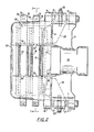
- Fig. 1 is a front elevation partly in section of a disc brake incorporating the present invention
- Figures 1 and 2 show a disc brake assembly generally designated by the numeral 10.
- the assembly 10 includes a floating caliper 12 mounted by means of circumferentially spaced, axially aligned pairs of bosses 14 and 15, and 16 and 17, on slide pins 19 and 20.
- the slide pins 19 and 20 are respectively secured by draw pins 23 within bores provided to bosses 21, 22 at the radially outer extremities of circumferentially spaced, radially extending arms 24, 25 of the brake supporting torque plate or spider 26.
- the torque plate 26 is provided with a circular array of apertures which receive a plurality of bolts 28 which in turn secure the support or torque plate 26 to a flange welded to a vehicle axle 29.
- a pair of rotors 30, 31 having first axially spaced radially extending oppositely disposed friction braking surfaces 32 and 34 are axially slidably mounted to an adapter 40 secured by means of a plurality of bolts 41 to a flange 44 of a wheel hub rotatably mounted in conventional manner by bearings provided at the end of the vehicle axle 29.
- the radially inward extending flange of a wheel 42 is also secured to the hub flange 44 by bolts 41.
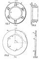
- the adapter 40 as best shown in Figures 3 and 4 has a radially extending mounting flange 46 and an axially extending cylindrical portion 48.
- Six axially extending ways 49 are evenly spaced around the circumference of the axially extending cylindrical portion 48.
- Rotors 30, 31 both of which are identical in structure and one of which is shown in Figures 5 and 6 are also annular or ring like in form having an inner periphery 38 and six radially outwardly directed grooves 39.
- the grooves 39 are evenly spaced about the inner periphery 38 of each rotor and are dimensioned to provide an axially sliding fit with the ways 49 provided to the adaptor 40.
- the rotor grooves 39 and the adaptor ways 49 thus provide a spline type mounting between the rotors 30, 31 and the adapter 40 which provide a rotary driving connection between the rotors and the adapter while permitting axial movement of each rotor relative to the axially extending cylindrical portion 48 of the adapter 40.
- the outline of a friction pad is also shown by phantom lines in Figure 5 to illustrate the general location and size of a friction pad relative to the rotor and that the outline and lateral edges of a spot or segment type friction pad of the present invention are contained within a 90° segment of the rotor 30 as represented by the angle L. f
- the caliper 12 is a cast metal component comprised of a depending leg 50 extending radially inward adjacent a second friction surface 36 of the rotor 30, an oppositely disposed depending leg or surface 51 adjacent a second radially extending friction surface 38 of rotor 31 and a bridge 52 extending over the radially outer periphery of the rotors 30, 31 and joining the leg 50 to the surface 51.
- the caliper 12 is formed with a generally cylindrical housing 54 extending to the right of the wall 51 as shown in Figure 2.
- the housing 54 is provided with a cylindrical bore 55 slidably mounting a piston 56 formed integrally with a load plate 58.
- the piston 56 and load plate 58 may be moved in the direction of the rotors 30, 31 by suitable hydraulic or mechanical actuating means.
- a powerscrew actuating means is utilized in the preferred embodiment.
- a powerscrew 60 having an integrally formed radially extending flange 61 seated against a radially extending surface 62 of a cap 64 bolted to the caliper 12 is utilized to move the piston 56 axially in the bore 55.
- Powerscrew 60 is splined at one end 65 for connection to an actuating lever 66 connected by means of a clevis to the push rod of an air motor 68.
- the powerscrew is provided with a multiple lead thread 69 which engages corresponding threads provided internally of a nut 70.
- the bridge 52 of caliper 12 is provided with an aperture 74 defined by a radially disposed edge 75, a pair of circumferentially spaced, axially extending, radially converging edges 76 and 78, and the radially inwardly extending caliper leg 50.
- the circumferentially spaced edges 76, 78 converge in a radial direction at an included angle of about 32°.
- the circumferentially spaced edges 76, 78 are each provided with a slot 79, 80.
- the bottoms 81, 82 of the slots 79, 80 are substantially parallel and the slots 79, 80 are located radially outward from the periphery of the rotor 31 so as to extend at least partly across the periphery of the rotor 31 as shown by Figure 2.
- a friction pad comprised of a backing plate having friction lining material secured to a major surface thereof is disposed between the piston 56 and the radially extending surface 38 of the rotor 31.
- a friction pad 92 comprised of a backing plate having friction lining materials secured to a major surface thereof is disposed between the caliper leg 50 and the radially extending surface 36 of the rotor 30.
- a friction pad 93 comprised of a backing plate having friction lining material secured to both of the oppositely disposed major surfaces thereof is disposed between the radially extending surface 32 of rotor 30 and the radially extending surface 34 of rotor 31.
- the friction pads 91, 92 and 93 are generally of the same shape and structure, the major exception being that friction pad 93 is provided with friction lining material on both major surfaces thereof whereas friction pads 91 and 92 are provided with friction lining material on the major surfaces facing the rotors 31 and 30 respectively.
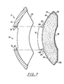
- each of the friction pads 91, 92 and 93 are comprised of a metal backing plate 94 of uniform thickness having friction material 95 secured to a major surface thereof.
- the major surface is defined by arcuate longitudinal edges 96 and 98 joined by circumferentially spaced lateral edges 99 and 100.
- the arcuate edge 98 is of greater radius than the edge 96 and extends radially outward to provide a supporting tab 101 of substantial circumferential length less than the distance between the lateral edges 99, 100.
- the supporting tab 101 is circumferentially bounded by radially converging edges 102 and 104.
- the backing plates also include abutment surfaces 105, 106 adjacent the radially converging edges 102 and 104 respectively.
- the friction pads 91, 92 and 93 are axially slidably supported in the caliper aperture 74 by means of the tabs 101.
- one of the slide pins 19, 20 is removed from its respective boss 21, 22 thereby permitting the caliper 12 to be pivoted about the other slide pin and exposing the interior of the caliper.
- the friction pads 91, 92 and 93 are installed and removed by aligning the friction pad backing plate tab 101 with the grooves 79 and 80 and in the case of insertion, to pass the tab 101 through the grooves 79 and 80 until the abutments 105, 106 contact the interior surface of the bridge 52 at which point the friction pad is displaced axially thereby axially slidably supporting the radially converging edges 102, 104 of the backing plate tab 101 on the circumferentially spaced radially converging edges 76, 78 of the caliper aperture 74.
- the radially converging edges 76, 78 of the caliper aperture 74 support the friction pads 91, 92, 93 in their previously described location relative to the rotors 30, 31 and prevent rotation of the friction pads 91, 92, 93 during actuation of the brake assembly while permitting axially slidably movement of the friction pads relative to the caliper 12.
- the brake assembly shown by Figure 1 is actuated by supplying fluid pressure to the motor 68 to rotate the lever arm 66 and powerscrew 60.
- Spline 71 provided to nut 70 prevent rotation of the nut which is then driven by the powerscrew threads to the left to move the force transmitting piston 56 and load plate 58 axially in the direction of the rotors 30, 31.
- the piston 56 moves the friction pad 91 into contact with surface 38 of rotor 31 which produces a reaction force in the powerscrew 60 which is transferred-by the powerscrew flange 61 to the radially extending surface 62 of the caliper cap 64.
- the reaction force transmitted between the abutting surfaces of the flange 61 and cap 64 moves the caliper 12 to the right as shown in Figures 1 and 2 while the powerscrew 60 continues to move the piston 56 to the left.
- the caliper leg 50 serves as an abutment limiting axial movement of the friction pad 92 away from the rotor 30 and as a result of the reaction force realized at the radially extending abutment surface 62 of the cap 64, the caliper 12 moves the friction pad 62 into contact with the surface 36 of rotor 30 and the friction pads 91 and 92 move at least one and possibly both of the rotors 30, 31 to produce frictional contact between the surfaces 32, 34 of the rotors 30, 31 and the friction pad 93.
- the brake is released by means of springs provided internally of the fluid motor 68, the piston 56 and the mechanics of the low lead angle of the powerscrew threads 69.
- the present invention thus provides a dual rotor disc brake utilizing friction pads which extend over less than 90% of the full circumference of the rotors thereby permitting actuation by means of a simple device located adjacent to friction pads and permitting the rotors to dissipate thermal energy as they rotate away from the pads in ambient air adjacent the vehicle wheel.
- the use of the two rotors and three friction pads actuated by a single power source also provides a substantial increase in the braking torque obtained by the brake assembly or the present invention that which is almost twice the braking torque obtained with a similar power source acting to engage a pair of friction padlat with a single rotor.
- the invention may also be embodied in other specific forms without departing from the spirit or essential characteritstics thereof.
- both rotors and all three friction pads be axially movable relative to the axle, the advantages offered by the present invention would still be achieved if one of the rotors or one of the friction pads were fixed against axial movement.
- the actuating means would then displace the remaining ones of the two rotors and three friction pads axially in the direction of the one which is axially fixed.
Landscapes
- Engineering & Computer Science (AREA)
- General Engineering & Computer Science (AREA)
- Mechanical Engineering (AREA)
- Braking Arrangements (AREA)
Applications Claiming Priority (2)
| Application Number | Priority Date | Filing Date | Title |
|---|---|---|---|
| US528325 | 1983-08-31 | ||
| US06/528,325 US4529067A (en) | 1983-08-31 | 1983-08-31 | Multiple disc brake |
Publications (2)
| Publication Number | Publication Date |
|---|---|
| EP0136434A1 true EP0136434A1 (fr) | 1985-04-10 |
| EP0136434B1 EP0136434B1 (fr) | 1988-04-20 |
Family
ID=24105211
Family Applications (1)
| Application Number | Title | Priority Date | Filing Date |
|---|---|---|---|
| EP84108553A Expired EP0136434B1 (fr) | 1983-08-31 | 1984-07-19 | Frein à disque |
Country Status (9)
| Country | Link |
|---|---|
| US (1) | US4529067A (fr) |
| EP (1) | EP0136434B1 (fr) |
| JP (1) | JPS6073137A (fr) |
| AU (1) | AU574369B2 (fr) |
| BR (1) | BR8404252A (fr) |
| CA (1) | CA1238585A (fr) |
| DE (1) | DE3470588D1 (fr) |
| ES (1) | ES535536A0 (fr) |
| MX (1) | MX160292A (fr) |
Cited By (3)
| Publication number | Priority date | Publication date | Assignee | Title |
|---|---|---|---|---|
| FR2643959A1 (fr) * | 1989-03-02 | 1990-09-07 | Sbarro Mottas Eng | Dispositif de freinage pour vehicule a deux roues ou vehicule automobile |
| WO1995021338A1 (fr) * | 1994-02-01 | 1995-08-10 | Lucas Industries Public Limited Company | Ensemble cylindre et frein |
| US6186286B1 (en) | 1997-12-16 | 2001-02-13 | Dr. Ing. H.C.F. Porsche Ag | Braking device |
Families Citing this family (24)
| Publication number | Priority date | Publication date | Assignee | Title |
|---|---|---|---|---|
| FR2567976B1 (fr) * | 1984-07-20 | 1990-05-18 | Dba | Frein a disque a etrier coulissant partiellement pivotant |
| US4727964A (en) * | 1986-10-08 | 1988-03-01 | Rockwell International Corporation | Air disc brake assembly with shortened end cap and integral cast air chamber bracket |
| US4865162A (en) * | 1986-12-15 | 1989-09-12 | Opus Acquisition Corporation | Electrically actuated aircraft brakes |
| US4844206A (en) * | 1987-12-18 | 1989-07-04 | Allied-Signal Inc. | Dual disk brake |
| US5046589A (en) * | 1990-04-10 | 1991-09-10 | Bright Larry G | Reduction of caliper lining wear in air brakes |
| US5348123A (en) * | 1991-09-02 | 1994-09-20 | Akebono Brake Industry Co., Ltd. | Brake actuating apparatus for a vehicle |
| US5348122A (en) * | 1993-02-01 | 1994-09-20 | The B. F. Goodrich Company | Sliding back leg brake |
| GB9625862D0 (en) | 1996-12-12 | 1997-01-29 | T & N Technology Ltd | Disc brake |
| FR2760809B1 (fr) * | 1997-03-14 | 1999-04-23 | Bosch Syst Freinage | Systeme de freinage multidisque hybride |
| DE19804426C2 (de) * | 1997-12-16 | 2000-06-08 | Porsche Ag | Bremseinrichtung |
| US6095293A (en) * | 1998-02-13 | 2000-08-01 | The B. F. Goodrich Company | Aircraft brake and method with electromechanical actuator modules |
| JP3911656B2 (ja) * | 1998-03-30 | 2007-05-09 | 株式会社日立製作所 | ディスクブレーキ |
| US6530625B2 (en) | 1999-08-27 | 2003-03-11 | Alliedsignal Inc. | Electrically actuated brake with vibration damping |
| SE0002316D0 (en) * | 2000-06-21 | 2000-06-21 | Haldex Brake Prod Ab | Disc brake |
| SE521910C2 (sv) * | 2000-07-12 | 2003-12-16 | Volvo Constr Equip Components | Uppsättning av våta bromsar och fordon med nämnda bromsuppsättning |
| US20040108174A1 (en) * | 2001-03-27 | 2004-06-10 | Baylis Christopher Stanford | Method and apparatus for disc brake construction |
| US6991075B2 (en) * | 2002-07-24 | 2006-01-31 | Delphi Technologies, Inc. | Electrically actuated disc brake assembly |
| AU2003292256A1 (en) * | 2002-12-23 | 2004-07-22 | Haldex Brake Products Ab | Brake gear for a disc brake |
| US20060151266A1 (en) * | 2005-01-12 | 2006-07-13 | Robert Bosch Corporation | A Corner Assembly for a Vehicle |
| DE102005006298A1 (de) * | 2005-02-11 | 2006-08-24 | Audi Ag | Mehrscheibenbremse für Fahrzeuge, insbesondere Doppelscheibenbremse für Kraftfahrzeuge |
| WO2009035348A1 (fr) * | 2007-09-14 | 2009-03-19 | Bas Manufacturing Limited | Améliorations apportées à des ensembles freins de roues |
| US8800726B2 (en) * | 2012-02-10 | 2014-08-12 | Eaton Corporation | Dual-rotor force transmitting assembly |
| SE537115C2 (sv) * | 2012-07-05 | 2015-01-20 | Scania Cv Ab | Lagerkonsolkonfiguration för trumbroms och metod för montering av en lagerkonsolkonfiguration |
| DE102023123185A1 (de) * | 2023-08-29 | 2025-03-06 | Schaeffler Technologies AG & Co. KG | Bremsvorrichtung für ein Fahrzeug mit mehreren Bremsscheiben und Kühlstruktur sowie Fahrzeug mit der Bremsvorrichtung |
Citations (1)
| Publication number | Priority date | Publication date | Assignee | Title |
|---|---|---|---|---|
| US3707207A (en) * | 1969-09-06 | 1972-12-26 | Aisin Seiki | Spot disc brakes for vehicles |
Family Cites Families (8)
| Publication number | Priority date | Publication date | Assignee | Title |
|---|---|---|---|---|
| US2934174A (en) * | 1957-07-09 | 1960-04-26 | Sarl Rech S Etudes Production | Multi-disc brake |
| US3237724A (en) * | 1964-01-31 | 1966-03-01 | Lambert & Brake Corp | Cam-operated, spot brake structure |
| US3295647A (en) * | 1964-11-23 | 1967-01-03 | Borg Warner | Multiple disc spot clutch with booster |
| GB1519980A (en) * | 1975-12-29 | 1978-08-02 | Goodrich Co B F | Disc brake |
| GB2049845B (en) * | 1979-05-16 | 1983-04-27 | Lucas Industries Ltd | Disc brakes |
| JPS5712135A (en) * | 1980-06-25 | 1982-01-22 | Nissin Kogyo Kk | Multiple-disk brake for vehicle |
| US4352414A (en) * | 1980-12-01 | 1982-10-05 | Rockwell International Corporation | Friction pad and support for a disc brake |
| US4406352A (en) * | 1980-12-01 | 1983-09-27 | Rockwell International Corporation | Disc brake actuator |
-
1983
- 1983-08-31 US US06/528,325 patent/US4529067A/en not_active Expired - Lifetime
-
1984
- 1984-07-19 DE DE8484108553T patent/DE3470588D1/de not_active Expired
- 1984-07-19 EP EP84108553A patent/EP0136434B1/fr not_active Expired
- 1984-07-23 AU AU30953/84A patent/AU574369B2/en not_active Ceased
- 1984-07-25 CA CA000459670A patent/CA1238585A/fr not_active Expired
- 1984-08-17 MX MX202419A patent/MX160292A/es unknown
- 1984-08-24 BR BR8404252A patent/BR8404252A/pt unknown
- 1984-08-30 ES ES535536A patent/ES535536A0/es active Granted
- 1984-08-30 JP JP59179481A patent/JPS6073137A/ja active Pending
Patent Citations (1)
| Publication number | Priority date | Publication date | Assignee | Title |
|---|---|---|---|---|
| US3707207A (en) * | 1969-09-06 | 1972-12-26 | Aisin Seiki | Spot disc brakes for vehicles |
Cited By (4)
| Publication number | Priority date | Publication date | Assignee | Title |
|---|---|---|---|---|
| FR2643959A1 (fr) * | 1989-03-02 | 1990-09-07 | Sbarro Mottas Eng | Dispositif de freinage pour vehicule a deux roues ou vehicule automobile |
| WO1995021338A1 (fr) * | 1994-02-01 | 1995-08-10 | Lucas Industries Public Limited Company | Ensemble cylindre et frein |
| US5819885A (en) * | 1994-02-01 | 1998-10-13 | Lucas Industries Public Limited Company | Brake and actuator assembly |
| US6186286B1 (en) | 1997-12-16 | 2001-02-13 | Dr. Ing. H.C.F. Porsche Ag | Braking device |
Also Published As
| Publication number | Publication date |
|---|---|
| BR8404252A (pt) | 1985-07-23 |
| DE3470588D1 (en) | 1988-05-26 |
| AU574369B2 (en) | 1988-07-07 |
| ES8506386A1 (es) | 1985-07-01 |
| EP0136434B1 (fr) | 1988-04-20 |
| MX160292A (es) | 1990-01-25 |
| JPS6073137A (ja) | 1985-04-25 |
| AU3095384A (en) | 1985-03-07 |
| CA1238585A (fr) | 1988-06-28 |
| ES535536A0 (es) | 1985-07-01 |
| US4529067A (en) | 1985-07-16 |
Similar Documents
| Publication | Publication Date | Title |
|---|---|---|
| US4529067A (en) | Multiple disc brake | |
| US3048250A (en) | Friction disc for brakes, clutches and the like | |
| US5012901A (en) | Self-energizing disc brakes | |
| RU2269695C2 (ru) | Дисковый тормоз с жесткозакрепленным суппортом, имеющий малый коэффициент взаимного перекрытия | |
| KR100471909B1 (ko) | 디스크 브레이크 시스템 | |
| US4352414A (en) | Friction pad and support for a disc brake | |
| US4282952A (en) | Wheel assembly | |
| US3780834A (en) | Disc brake assembly | |
| GB2064066A (en) | Friction brake | |
| US3261429A (en) | Brake | |
| US4234061A (en) | Disc brakes for vehicles | |
| EP0096553A1 (fr) | Assemblages de disque pour freins | |
| WO2001036835A1 (fr) | Rotor avec ailettes pour ensemble frein a disque | |
| US4214648A (en) | Vehicle disc brake | |
| US3303911A (en) | Fluid cooled brake mechanism | |
| EP0135696B1 (fr) | Frein à disque, mâchoire et support de stabilisation | |
| GB2163500A (en) | Disk brake | |
| US4516666A (en) | Disc brake anti-rattle means | |
| GB2088500A (en) | Disc brake anti-rattle spring clip | |
| US3346075A (en) | Guide means for a caliper of a disc brake | |
| US3782508A (en) | Releasable caliper retaining means for a disc brake | |
| US3311198A (en) | Disc brake | |
| EP0139890B1 (fr) | Mâchoire et support pour un frein à disque | |
| EP0385744A1 (fr) | Freins à disque pour véhicules | |
| CA1038308A (fr) | Frein a disque a l'epreuve des pannes |
Legal Events
| Date | Code | Title | Description |
|---|---|---|---|
| PUAI | Public reference made under article 153(3) epc to a published international application that has entered the european phase |
Free format text: ORIGINAL CODE: 0009012 |
|
| AK | Designated contracting states |
Designated state(s): BE CH DE FR GB IT LI NL SE |
|
| 17P | Request for examination filed |
Effective date: 19850927 |
|
| 17Q | First examination report despatched |
Effective date: 19861128 |
|
| GRAA | (expected) grant |
Free format text: ORIGINAL CODE: 0009210 |
|
| AK | Designated contracting states |
Kind code of ref document: B1 Designated state(s): BE CH DE FR GB IT LI NL SE |
|
| REF | Corresponds to: |
Ref document number: 3470588 Country of ref document: DE Date of ref document: 19880526 |
|
| ET | Fr: translation filed | ||
| ITF | It: translation for a ep patent filed | ||
| PLBE | No opposition filed within time limit |
Free format text: ORIGINAL CODE: 0009261 |
|
| STAA | Information on the status of an ep patent application or granted ep patent |
Free format text: STATUS: NO OPPOSITION FILED WITHIN TIME LIMIT |
|
| 26N | No opposition filed | ||
| PGFP | Annual fee paid to national office [announced via postgrant information from national office to epo] |
Ref country code: SE Payment date: 19890619 Year of fee payment: 6 |
|
| PGFP | Annual fee paid to national office [announced via postgrant information from national office to epo] |
Ref country code: DE Payment date: 19890706 Year of fee payment: 6 |
|
| PGFP | Annual fee paid to national office [announced via postgrant information from national office to epo] |
Ref country code: FR Payment date: 19890707 Year of fee payment: 6 |
|
| PGFP | Annual fee paid to national office [announced via postgrant information from national office to epo] |
Ref country code: CH Payment date: 19890710 Year of fee payment: 6 |
|
| PGFP | Annual fee paid to national office [announced via postgrant information from national office to epo] |
Ref country code: BE Payment date: 19890714 Year of fee payment: 6 |
|
| ITTA | It: last paid annual fee | ||
| PGFP | Annual fee paid to national office [announced via postgrant information from national office to epo] |
Ref country code: NL Payment date: 19890731 Year of fee payment: 6 Ref country code: GB Payment date: 19890731 Year of fee payment: 6 |
|
| PG25 | Lapsed in a contracting state [announced via postgrant information from national office to epo] |
Ref country code: GB Effective date: 19900719 |
|
| PG25 | Lapsed in a contracting state [announced via postgrant information from national office to epo] |
Ref country code: SE Effective date: 19900720 |
|
| PG25 | Lapsed in a contracting state [announced via postgrant information from national office to epo] |
Ref country code: LI Effective date: 19900731 Ref country code: CH Effective date: 19900731 Ref country code: BE Effective date: 19900731 |
|
| BERE | Be: lapsed |
Owner name: ROCKWELL INTERNATIONAL CORP. Effective date: 19900731 |
|
| PG25 | Lapsed in a contracting state [announced via postgrant information from national office to epo] |
Ref country code: NL Effective date: 19910201 |
|
| NLV4 | Nl: lapsed or anulled due to non-payment of the annual fee | ||
| GBPC | Gb: european patent ceased through non-payment of renewal fee | ||
| REG | Reference to a national code |
Ref country code: CH Ref legal event code: PL |
|
| PG25 | Lapsed in a contracting state [announced via postgrant information from national office to epo] |
Ref country code: FR Effective date: 19910329 |
|
| PG25 | Lapsed in a contracting state [announced via postgrant information from national office to epo] |
Ref country code: DE Effective date: 19910403 |
|
| REG | Reference to a national code |
Ref country code: FR Ref legal event code: ST |
|
| EUG | Se: european patent has lapsed |
Ref document number: 84108553.3 Effective date: 19910402 |