EP0136436A1 - Kolbenstangenloser Arbeitszylinder - Google Patents
Kolbenstangenloser Arbeitszylinder Download PDFInfo
- Publication number
- EP0136436A1 EP0136436A1 EP84108577A EP84108577A EP0136436A1 EP 0136436 A1 EP0136436 A1 EP 0136436A1 EP 84108577 A EP84108577 A EP 84108577A EP 84108577 A EP84108577 A EP 84108577A EP 0136436 A1 EP0136436 A1 EP 0136436A1
- Authority
- EP
- European Patent Office
- Prior art keywords
- braking device
- braking
- cylinder tube
- actuating device
- power take
- Prior art date
- Legal status (The legal status is an assumption and is not a legal conclusion. Google has not performed a legal analysis and makes no representation as to the accuracy of the status listed.)
- Granted
Links
Images

Classifications
-
- F—MECHANICAL ENGINEERING; LIGHTING; HEATING; WEAPONS; BLASTING
- F15—FLUID-PRESSURE ACTUATORS; HYDRAULICS OR PNEUMATICS IN GENERAL
- F15B—SYSTEMS ACTING BY MEANS OF FLUIDS IN GENERAL; FLUID-PRESSURE ACTUATORS, e.g. SERVOMOTORS; DETAILS OF FLUID-PRESSURE SYSTEMS, NOT OTHERWISE PROVIDED FOR
- F15B15/00—Fluid-actuated devices for displacing a member from one position to another; Gearing associated therewith
- F15B15/08—Characterised by the construction of the motor unit
- F15B15/084—Characterised by the construction of the motor unit the motor being of the rodless piston type, e.g. with cable, belt or chain
-
- A—HUMAN NECESSITIES
- A47—FURNITURE; DOMESTIC ARTICLES OR APPLIANCES; COFFEE MILLS; SPICE MILLS; SUCTION CLEANERS IN GENERAL
- A47L—DOMESTIC WASHING OR CLEANING; SUCTION CLEANERS IN GENERAL
- A47L15/00—Washing or rinsing machines for crockery or tableware
- A47L15/42—Details
- A47L15/4229—Water softening arrangements
-
- B—PERFORMING OPERATIONS; TRANSPORTING
- B23—MACHINE TOOLS; METAL-WORKING NOT OTHERWISE PROVIDED FOR
- B23Q—DETAILS, COMPONENTS, OR ACCESSORIES FOR MACHINE TOOLS, e.g. ARRANGEMENTS FOR COPYING OR CONTROLLING; MACHINE TOOLS IN GENERAL CHARACTERISED BY THE CONSTRUCTION OF PARTICULAR DETAILS OR COMPONENTS; COMBINATIONS OR ASSOCIATIONS OF METAL-WORKING MACHINES, NOT DIRECTED TO A PARTICULAR RESULT
- B23Q1/00—Members which are comprised in the general build-up of a form of machine, particularly relatively large fixed members
- B23Q1/25—Movable or adjustable work or tool supports
- B23Q1/26—Movable or adjustable work or tool supports characterised by constructional features relating to the co-operation of relatively movable members; Means for preventing relative movement of such members
- B23Q1/28—Means for securing sliding members in any desired position
-
- F—MECHANICAL ENGINEERING; LIGHTING; HEATING; WEAPONS; BLASTING
- F15—FLUID-PRESSURE ACTUATORS; HYDRAULICS OR PNEUMATICS IN GENERAL
- F15B—SYSTEMS ACTING BY MEANS OF FLUIDS IN GENERAL; FLUID-PRESSURE ACTUATORS, e.g. SERVOMOTORS; DETAILS OF FLUID-PRESSURE SYSTEMS, NOT OTHERWISE PROVIDED FOR
- F15B15/00—Fluid-actuated devices for displacing a member from one position to another; Gearing associated therewith
- F15B15/20—Other details, e.g. assembly with regulating devices
- F15B15/26—Locking mechanisms
- F15B15/262—Locking mechanisms using friction, e.g. brake pads
-
- F—MECHANICAL ENGINEERING; LIGHTING; HEATING; WEAPONS; BLASTING
- F15—FLUID-PRESSURE ACTUATORS; HYDRAULICS OR PNEUMATICS IN GENERAL
- F15B—SYSTEMS ACTING BY MEANS OF FLUIDS IN GENERAL; FLUID-PRESSURE ACTUATORS, e.g. SERVOMOTORS; DETAILS OF FLUID-PRESSURE SYSTEMS, NOT OTHERWISE PROVIDED FOR
- F15B15/00—Fluid-actuated devices for displacing a member from one position to another; Gearing associated therewith
- F15B15/20—Other details, e.g. assembly with regulating devices
- F15B15/26—Locking mechanisms
- F15B15/265—Locking mechanisms specially adapted for rodless pistons or slotted cylinders
Definitions
- the invention relates to a braking device for axial movements, which acts on the surface of a cylinder tube, preferably for working cylinders or the like.
- the braking device is integrated in its power take-off, and its metered control is preferably carried out by means of a fluid.
- Braking devices for working cylinders are known, for example DE-OS 2945133 shows such a braking device which is integrated in the power take-off of the working cylinder and is supported on the cylinder tube.
- Such a brake is not suitable for universal use for several reasons. This is particularly the case when positioning in the fluid-controlled brake system by means of targeted, metered pressure release and, at the same time, safety braking must be possible in the event of pressure loss.
- a brake system for working cylinders is set up for operation at a pressure of 6 bar, this operating pressure enables trouble-free operation up to about 5 bar.
- the braking effect starts and is fully effective at a pressure of around 1 bar, i.e. the full braking effect is available. If, for example, the pressure in the brake system drops to this value, this means a malfunction and the braking device will go into its active position with full braking force.
- the invention is therefore based on the object of having a braking device for working cylinders with which G Renz events are manageable and holding the working cylinder when the pressure loss and also the same for the positioning is appropriate.
- a brake member is wrapped around the outer jacket of the working cylinder and is under the action of a prestressed actuator.
- the braking member is advantageously a rope.
- An embodiment variant provides that instead of a rope, a band or a chain serves as a braking link.
- the advantage of the brake device for working cylinders proposed by the invention lies in the fact that they can be used universally, and even borderline cases can be detected.
- the subject matter of the invention can also be used advantageously in neighboring fields of technology, e.g. as a safety device on axially moving machine parts, in flow and conveyor technology, on vehicle parts, in automation etc.
- the working cylinder shown in the figures consists essentially of a cylinder tube 1 and one Power take-off 2, as well as a drive for this power take-off.
- drives and power transmission members for example, steel strips 3, which are suspended on the fluid-actuated piston 4 and on the power take-off 2, come into question.
- Pins, etc., attached to the piston 4 are also common as power transmission members, they may also serve as a power take-off and protrude through the cylinder wall.
- a guide bushing which comprises the tube 1 of the working cylinder and, in addition to the power take-off 2, also carries a base plate 6 for the braking device.
- the braking device consists of a fluid-actuated bellows 7, which is supported at the top against a pressure plate 8 and at the bottom against an intermediate plate 9, a retaining ring 10 for the bellows 7 being arranged on the intermediate plate 9, which in turn is fixed in position by means of screws 11.
- the bolts 12a and 12b are anchored in the intermediate plate 6 and serve as a guide for the intermediate plate 9, which is pressed upwards onto the bellows 7 by plate springs 13a and 13b pulled over the bolts 12a and 12b.
- the actual brake member 14 preferably consists of ' one or more wire cables which are fastened in the holder 15 and are guided around the cylinder tube 1 with at least one loop. Between the cylinder tube 1 and the brake member 14 there are 5 brake bodies 16 in the guide bushing. The brake bodies 16, supported in the guide bush 5, are effectively supported against axially acting forces.
- a cover plate 17 is provided above the pressure plate 8, the adjusting screws 18a and 18b for the pressure plate 8 contains.
- screw bolts 19a and 19b are provided in the base plate 6 and penetrate the cover plate 17.
- two guide bands 20a and 20b are arranged in the guide bush 5.
- the length of the fluid-actuated bellows 7 is sufficiently dimensioned at approx. 5.0 bar pressurization at approx. 10 cm and at a width of 4 cm.
Landscapes
- Engineering & Computer Science (AREA)
- Mechanical Engineering (AREA)
- Physics & Mathematics (AREA)
- Fluid Mechanics (AREA)
- General Engineering & Computer Science (AREA)
- Actuator (AREA)
- Washing And Drying Of Tableware (AREA)
Abstract
Description
- Die Erfindung bezieht sich auf eine Bremseinrichtung für axiale Bewegungsabläufe, die auf die Oberfläche eines Zylinderrohres einwirkt, vorzugsweise für Arbeitszylinder oder dergl., wobei die Bremseinrichtung in dessen Kraftabnahme integriert ist, und wobei deren dosierte Steuerung vorzugsweise mittels eines Fluids vorgenommen ist.
- Bremseinrichtungen für Arbeitszylinder sind bekannt, so zeigt beispielsweise die DE-OS 2945133 eine solche Bremseinrichtung, die in die Kraftabnahme des Arbeitszylinders integriert ist und sich am Zylinderrohr abstützt.
- Für universellen Einsatz ist eine solche Bremse aus mehreren Gründen nicht geeignet. Dies besonders dann, wenn mittels gezielter, dosierter Druckwegnahme im fluidgesteuerten Bremssystem positioniert werden soll und gleichzeitig bei Druckausfall eine Sicherheitsbremsung möglich sein muß. Beispielsweise ist ein solches Bremssystem für Arbeitszylinder für einen Betrieb mit einem Druck von.6 bar eingerichtet, dieser Betriebsdruck ermöglicht ein einwandfreies Arbeiten bis etwa 5 bar. Bei geringeren Werten setzt die Bremswirkung ein und ist bei einnem Druck von etwa 1 bar voll wirksam, d.h. es steht die volle Bremswirkung zur Verfügung. Fällt beispielsweise der Druck im Bremssystem auf diesen Wert ab, bedeutet dies einen Störungsfall und die Bremseinrichtung wird mit voller Bremskraft in ihre Wirkstellung gehen.
- Der Erfindung liegt daher die Aufgabe zugrunde, eine Bremseinrichtung für Arbeitszylinder zu besitzen, mit der auch Grenzfälle beherrschbar sind und die bei Druckausfall den Arbeitszylinder anhält und außerdem für das Positionieren desselben geeignet ist.
- Erfindungsgemäß wird dies dadurch erreicht, daß ein Bremsglied um den Außenmantel des Arbeitszylinders geschlungen ist und unter der Wirkung eines vorgespannten Betätigungsgliedes steht.
- Vorteilhafterweise ist das Bremsglied ein Seil.
- Eine Ausführungsvariante sieht vor, daß anstelle eines Seiles, ein Band oder eine Kette als Bremsglied dient.
- Der Vorteil, der mit der Erfindung vorgeschlagenen Bremseinrichtung für Arbeitszylinder liegt in deren universellen Einsatzmöglichkeit, wobei sogar Grenzfälle erfaßt werden können. Auch auf benachbarten Gebieten der Technik, ist der Erfindungsgegenstand mit Vorteil einsetzbar, so z.B. als Sicherheitseinrichtung an axial bewegten Maschinenteilen, in der Strömungs- und Fördertechnik, an Fahrzeugteilen, in der Automation etc.
- Der Erfindung ist nachstehend anhand eines in den Abbildungen dargestellten Ausführungsbeispieles näher erläutert.
- Es zeigt:
- Fig. 1 einen Längsschnitt durch den Erfindungsgegenstand und
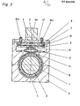
- Fig. 2 einen Schnitt durch die Fig. 1 in Richtung A-A
- Der in den Abbildungen dargestellte Arbeitszylinder besteht im wesentlichen aus einem Zylinderrohr 1 und einer Kraftabnahme 2, sowie einem Antrieb für diese Kraftabnahme. Als Antriebe und Kraftübertragungsglieder kommen beispielsweise Stahlbänder 3, die am fluidbetätigen Kolben 4 und an der Kraftabnahme 2 eingehängt sind, in Frage. Auch am Kolben 4 befestigte Zapfen etc. sind als Kraftübertragungsglieder üblich, sie dienen ggf. gleichzeitig als Kraftabnahme und ragen durch die Zylinderwand.
- Mit 5 ist eine Führungsbuchse bezeichnet, die das Rohr 1 des Arbeitszylinders umfasst und außer der Kraftabnahme 2 noch eine Grundplatte 6 für die Bremseinrichtung trägt.
- Die Bremseinrichtung besteht aus einem fluidbetätigten Balg 7, der sich oben gegen eine Druckplatte 8 und unten gegen eine Zwischenplatte 9 abstützt, wobei auf der Zwischenplatte 9 ein Haltering 10 für den Balg 7 angeordnet ist, der seinerseits mittels Schrauben 11 in seiner Lage fixiert ist.
- Die Bolzen 12a und 12b sind in der Zwischenplatte 6 verankert und dienen der Zwischenplatte 9 als Führung, die von über die Bolzen 12a und 12b gezogenen Tellerfedern 13a und 13b nach oben auf den Balg 7 gedrückt wird.
- Das eigentliche Bremsglied 14 besteht vorzugsweise aus' einem oder mehreren Drahtseilen, die in der Halterung 15 befestigt und um das Zylinderrohr 1 mit mindestens einer Schlinge geführt sind. Zwischen dem Zylinderrohr 1 und dem Bremsglied 14 befinden sich in der Führungsbuchse 5 Bremskörper 16. Diese Bremskörper 16 sind außen metallisch belegt, um ein einwandfreies Gleiten z.B. der Drahtzeile auf dem Bremskörper zu ermöglichen. Gegen axial wirkende Kräfte sind die Bremskörper 16, in der Führungsbuchse 5 gelagert, wirksam abgestützt.
- Oberhalb der Druckplatte 8 ist eine Deckplatte 17 vorgesehen, die Justierschrauben 18a und 18b für die Druckplatte 8 enthält. Zum Einregulieren der Vorspannung der Bremseinrichtung sind Schraubbolzen 19a und 19b in der Grundplatte 6 vcrgesehen, die die Deckplatte 17 durchdringen. Um ein gutes Gleiten der Kraftabnahme mit ihrer Bremseinrichtung auf dem Zylinderrohr 1 zu gewährleisten, sind zwei Führungsbänder 20a und 20b in der Führungsbuchse 5 angeordnet.
- Die Wirkungsweise der erfindungsgemäßen Bremseinrichtung ist wie folgt:
- Fällt der-Druck in dem mit einem unter Druck stehenden Fluid gefüllten Balg 7a ab, so wird durch die Spannung der Tellerfedern 13a und 13b die Zwischenplatte 9 gegen die Druckplatte 8 gehoben, wodurch das Seil 14 gespannt wird und sich fest um das Zylinderrohr 1 schlingt. Dabei wird der Bremsbelag 16.gegen die Oberfläche des Zylinderrohres 1 gedrückt. Dies hat eine rasch ansprechende und stark wirkende Abbremsung der Bewegung der Kraftabnahme 2 zur Folge. Die Bremseinrichtung kann selbstverständlich auch umgekehrt arbeitend ausgebildet sein, d.h. das Bremsglied 14 geht bei Druckerhöhung im Bremssystem in Wirkstellung.
- Beispiel:
- Beträgt die benötigte Bremskraft beispielsweise 700 N, der Reibungskoeffizient ϑ ca. 0,2 , so wird eine Anpresskraft von ca. 3500 N benötigt. Die zugehörige Zugkraft beträgt bei einmaliger Umschlingung des Zylinderrohres ca. 900 N je Seilende (2 Seile). Bei zweimaliger Umschlingung des Zylinderrohres 1 durch die beiden Drahtseile beträgt die benötigte Zugkraft ca.450 N je Seilende, die Bremskraft, wie gefordert, unter Berücksichtigung der Eigenreibung im System also ca 700 N, wobei ausreichende Sicherheit gegeben ist.
- Die Länge des fluidbetätigten Balges 7 ist bei ca. 5,0 bar Druckbeaufschlagung mit ca. 10cm und bei einer Breite von 4cm ausreichend bemessen.
- Durch mehrmaliges Umschlingen des Zylinderrohres 1 mit dem Drahtseil 14 oder dergl. kann somit ein sehr großer Bremseffekt bei geringem Druckaufwand erzielt werden.
Claims (8)
Applications Claiming Priority (2)
| Application Number | Priority Date | Filing Date | Title |
|---|---|---|---|
| DE19833328352 DE3328352A1 (de) | 1983-08-05 | 1983-08-05 | Bremseinrichtung fuer arbeitszylinder oder dergl. |
| DE3328352 | 1983-08-05 |
Publications (2)
| Publication Number | Publication Date |
|---|---|
| EP0136436A1 true EP0136436A1 (de) | 1985-04-10 |
| EP0136436B1 EP0136436B1 (de) | 1987-12-02 |
Family
ID=6205903
Family Applications (1)
| Application Number | Title | Priority Date | Filing Date |
|---|---|---|---|
| EP84108577A Expired EP0136436B1 (de) | 1983-08-05 | 1984-07-20 | Kolbenstangenloser Arbeitszylinder |
Country Status (3)
| Country | Link |
|---|---|
| EP (1) | EP0136436B1 (de) |
| DE (2) | DE3328352A1 (de) |
| IT (1) | IT1176548B (de) |
Cited By (4)
| Publication number | Priority date | Publication date | Assignee | Title |
|---|---|---|---|---|
| FR2612311A1 (fr) * | 1987-03-12 | 1988-09-16 | Menissier Pierre | Dispositif a declenchement brusque utilisant un verin actionne par un fluide primaire et verrouillable par un deuxieme fluide |
| EP0554727A1 (de) * | 1992-01-23 | 1993-08-11 | Smc Corporation | Kolbenstangenlose Zylindereinheit mit Bremse |
| EP0965764A3 (de) * | 1998-06-17 | 2000-11-02 | Luciano Migliori | Feder- Verriegelungsvorrichtung |
| DE102006034469A1 (de) * | 2005-12-28 | 2007-07-05 | Volkswagen Ag | Befestigungssystem zur aktiven radialen Klemmung von axial verschiebbaren Lagerelementen |
Citations (4)
| Publication number | Priority date | Publication date | Assignee | Title |
|---|---|---|---|---|
| US3362505A (en) * | 1965-02-10 | 1968-01-09 | Avco Corp | Band brake |
| DE2322038A1 (de) * | 1973-05-02 | 1974-11-07 | Stahl Aufzuege | Sicherheitseinrichtung fuer hydraulische aufzuege |
| EP0029188A2 (de) * | 1979-11-08 | 1981-05-27 | Robert Bosch Gmbh | Bremseinrichtung für kolbenstangenlose Arbeitszylinder |
| DE3137141A1 (de) * | 1981-09-18 | 1983-04-14 | Festo-Maschinenfabrik Gottlieb Stoll, 7300 Esslingen | "arbeitszylinder" |
-
1983
- 1983-08-05 DE DE19833328352 patent/DE3328352A1/de not_active Withdrawn
-
1984
- 1984-07-20 EP EP84108577A patent/EP0136436B1/de not_active Expired
- 1984-07-20 DE DE8484108577T patent/DE3467911D1/de not_active Expired
- 1984-08-02 IT IT22195/84A patent/IT1176548B/it active
Patent Citations (4)
| Publication number | Priority date | Publication date | Assignee | Title |
|---|---|---|---|---|
| US3362505A (en) * | 1965-02-10 | 1968-01-09 | Avco Corp | Band brake |
| DE2322038A1 (de) * | 1973-05-02 | 1974-11-07 | Stahl Aufzuege | Sicherheitseinrichtung fuer hydraulische aufzuege |
| EP0029188A2 (de) * | 1979-11-08 | 1981-05-27 | Robert Bosch Gmbh | Bremseinrichtung für kolbenstangenlose Arbeitszylinder |
| DE3137141A1 (de) * | 1981-09-18 | 1983-04-14 | Festo-Maschinenfabrik Gottlieb Stoll, 7300 Esslingen | "arbeitszylinder" |
Cited By (5)
| Publication number | Priority date | Publication date | Assignee | Title |
|---|---|---|---|---|
| FR2612311A1 (fr) * | 1987-03-12 | 1988-09-16 | Menissier Pierre | Dispositif a declenchement brusque utilisant un verin actionne par un fluide primaire et verrouillable par un deuxieme fluide |
| EP0554727A1 (de) * | 1992-01-23 | 1993-08-11 | Smc Corporation | Kolbenstangenlose Zylindereinheit mit Bremse |
| US5469940A (en) * | 1992-01-23 | 1995-11-28 | Smc Corporation | Rodless cylinder unit with brake |
| EP0965764A3 (de) * | 1998-06-17 | 2000-11-02 | Luciano Migliori | Feder- Verriegelungsvorrichtung |
| DE102006034469A1 (de) * | 2005-12-28 | 2007-07-05 | Volkswagen Ag | Befestigungssystem zur aktiven radialen Klemmung von axial verschiebbaren Lagerelementen |
Also Published As
| Publication number | Publication date |
|---|---|
| IT8422195A0 (it) | 1984-08-02 |
| EP0136436B1 (de) | 1987-12-02 |
| DE3328352A1 (de) | 1985-02-14 |
| IT1176548B (it) | 1987-08-18 |
| DE3467911D1 (en) | 1988-01-14 |
| IT8422195A1 (it) | 1986-02-02 |
Similar Documents
| Publication | Publication Date | Title |
|---|---|---|
| DE2921983C2 (de) | ||
| EP0029188B1 (de) | Bremseinrichtung für kolbenstangenlose Arbeitszylinder | |
| DE69303795T2 (de) | Ausgleicheinrichtung für roboterarme | |
| EP0464368B1 (de) | Vorrichtung zum Umwickeln eines Gutstapels mit einer gedehnten Folie | |
| EP0136435A1 (de) | Arbeitszylinder mit Bremseinrichtung | |
| DE3016696A1 (de) | Einrichtung an bandzylindern | |
| EP0136436B1 (de) | Kolbenstangenloser Arbeitszylinder | |
| DE2937293C2 (de) | Seilandruckvorrichtung für Seilscheiben | |
| EP2706032B1 (de) | Lastaufnahmevorrichtung, insbesondere Unterflasche für ein Hebezeug | |
| DE4342716A1 (de) | Hubvorrichtung für ein Handhabungsgerät | |
| DE10113561B4 (de) | Vorschubvorrichtung für eine Ramm- und/oder Bohrvorrichtung | |
| EP0569111A1 (de) | Gleitschutzvorrichtung für Kraftfahrzeuge | |
| DE2262942C3 (de) | Pendelbremse für hydraulische Greifer | |
| EP0161437B1 (de) | Seilkran | |
| CH657084A5 (de) | Rollabdeckung einer fuehrungsbahn fuer einen schlitten an einer werkzeugmaschine. | |
| DE102018105102A1 (de) | Fangzylinder sowie Lasthebemittel mit einem Fangzylinder | |
| EP0097804B1 (de) | Ankerkettenstopper | |
| DE2853460A1 (de) | Wickelvorrichtung | |
| DE2829201C2 (de) | ||
| DE2919707C2 (de) | Vorrichtung zur selbsttätigen Einhaltung einer vorgegebenen Spannkraft in einem Fahrdraht oder Tragseil von Oberleitungen elektrischer Bahnen | |
| EP0168628B1 (de) | Kippgeschirr zum Hantieren schwerer Rollen | |
| EP1736208A1 (de) | Vorrichtung zun Sichern, Auf- und Abseilen von Personen und/oder Gütern | |
| DE8514700U1 (de) | Arbeitsgerät zum Zerbrechen von Felsgestein | |
| CH670413A5 (de) | ||
| DE3640149A1 (de) | Spann- und havarieschutzeinrichtung fuer schutzabdeckungen an fuehrungsbahnen von werkzeugmaschinen |
Legal Events
| Date | Code | Title | Description |
|---|---|---|---|
| PUAI | Public reference made under article 153(3) epc to a published international application that has entered the european phase |
Free format text: ORIGINAL CODE: 0009012 |
|
| 17P | Request for examination filed |
Effective date: 19840720 |
|
| AK | Designated contracting states |
Designated state(s): DE FR GB IT |
|
| 17Q | First examination report despatched |
Effective date: 19860206 |
|
| GRAA | (expected) grant |
Free format text: ORIGINAL CODE: 0009210 |
|
| AK | Designated contracting states |
Kind code of ref document: B1 Designated state(s): DE FR GB IT |
|
| REF | Corresponds to: |
Ref document number: 3467911 Country of ref document: DE Date of ref document: 19880114 |
|
| ET | Fr: translation filed | ||
| GBT | Gb: translation of ep patent filed (gb section 77(6)(a)/1977) | ||
| ITF | It: translation for a ep patent filed | ||
| PLBE | No opposition filed within time limit |
Free format text: ORIGINAL CODE: 0009261 |
|
| STAA | Information on the status of an ep patent application or granted ep patent |
Free format text: STATUS: NO OPPOSITION FILED WITHIN TIME LIMIT |
|
| 26N | No opposition filed | ||
| PGFP | Annual fee paid to national office [announced via postgrant information from national office to epo] |
Ref country code: GB Payment date: 19910709 Year of fee payment: 8 |
|
| PGFP | Annual fee paid to national office [announced via postgrant information from national office to epo] |
Ref country code: FR Payment date: 19910730 Year of fee payment: 8 |
|
| ITTA | It: last paid annual fee | ||
| PGFP | Annual fee paid to national office [announced via postgrant information from national office to epo] |
Ref country code: DE Payment date: 19910930 Year of fee payment: 8 |
|
| PG25 | Lapsed in a contracting state [announced via postgrant information from national office to epo] |
Ref country code: GB Effective date: 19920720 |
|
| GBPC | Gb: european patent ceased through non-payment of renewal fee |
Effective date: 19920720 |
|
| PG25 | Lapsed in a contracting state [announced via postgrant information from national office to epo] |
Ref country code: FR Effective date: 19930331 |
|
| PG25 | Lapsed in a contracting state [announced via postgrant information from national office to epo] |
Ref country code: DE Effective date: 19930401 |
|
| REG | Reference to a national code |
Ref country code: FR Ref legal event code: ST |