EP0136446A1 - Vibrationsförderer - Google Patents
Vibrationsförderer Download PDFInfo
- Publication number
- EP0136446A1 EP0136446A1 EP84108772A EP84108772A EP0136446A1 EP 0136446 A1 EP0136446 A1 EP 0136446A1 EP 84108772 A EP84108772 A EP 84108772A EP 84108772 A EP84108772 A EP 84108772A EP 0136446 A1 EP0136446 A1 EP 0136446A1
- Authority
- EP
- European Patent Office
- Prior art keywords
- workpiece
- guideway
- leaf springs
- vibration
- base frame
- Prior art date
- Legal status (The legal status is an assumption and is not a legal conclusion. Google has not performed a legal analysis and makes no representation as to the accuracy of the status listed.)
- Granted
Links
Images


Classifications
-
- B—PERFORMING OPERATIONS; TRANSPORTING
- B65—CONVEYING; PACKING; STORING; HANDLING THIN OR FILAMENTARY MATERIAL
- B65G—TRANSPORT OR STORAGE DEVICES, e.g. CONVEYORS FOR LOADING OR TIPPING, SHOP CONVEYOR SYSTEMS OR PNEUMATIC TUBE CONVEYORS
- B65G27/00—Jigging conveyors
- B65G27/08—Supports or mountings for load-carriers, e.g. framework, bases, spring arrangements
Definitions
- the invention relates to a device according to the preamble of the main claim.
- Corresponding vibratory conveyors are mainly used for feeding workpieces to workpiece processing machines, partly as vibratory bowl feeders and partly as linear vibratory conveyors.
- the direction of extension of the leaf springs carrying the workpiece guideway lies obliquely upwards. This means that the oscillation has an obliquely upward component. This leads to a throwing effect on the workpiece. This causes considerable noise pollution, reduces performance, increases wear and also brings about the risk of some damage to the workpiece surface on relatively sensitive workpieces.
- the object of the invention is to design a generic device without additional effort so that the aforementioned disadvantages are avoided.
- a recoil abutment weight provided according to the invention on the base frame increases the performance or facilitates the selection of a suitable vibration drive. It influences the effect which determines the direction of conveyance of the workpieces, namely that the workpiece moves in the direction in which the displacement speed of the workpiece guideway is lower than the displacement speed in the opposite direction, ie the displacement resulting from the return speed of the springs .
- the arrangement of the vibrating armature of a corresponding magnetic drive between two leaf springs at the level of the vibration level is the cheapest spatial allocation and also avoids any leverage that adversely affects the vibration of the leaf springs.
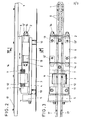
- the device shown in FIGS. 1 and 2 has a rectangular base plate 4 standing on four elastic buffers 10, on one end of which a bracket 11 for the horizontal reception of the magnetic core 12 and thus fastening of the electromagnet 3, and on the other hand two spring abutments 13, which in turn are arranged are connected to the table 6 and the latter preferably carries a workpiece guideway 1 in the center on its upper side.
- the table 6 is with the as an electric Magnet 3 trained vibration drive connected on its underside by means of a vibrating armature 7 located approximately at the level of the spring vibration level, the cross-sectional dimension of which corresponds to that of the magnetic core 12.
- the leaf springs 2 which extend transversely to the workpiece guideway 1, oscillate parallel to it and bring about the required restoring force, are carried by the two spring abutments 13 and connected to them.
- the two of the arrangement of the leaf springs 2 arranged transversely to the longitudinal extent of the workpiece guideway 1 spring abutment 13 establish a resilient connection between the base plate 4 and the workpiece guideway 1 supporting table 6 by on the one hand with the base plate 4 and on the other hand with the are connected to the supporting table 6, the table-side connection points being formed by spring abutments 13 ′ fixed on the underside of the table, alternately on two opposite sides of the workpiece guideway 1.
- the workpiece guideway 1 is firmly connected to the table 6, wherein the workpiece guideway 1 can be adjusted in relation to the supporting table 6 in the longitudinal direction.
- a recoil abutment weight 5 which is fixedly connected to it and is in the form of a metal block.
- the workpiece guideway 1 shown in FIG. 5 is designed such that a groove 8 extends from its upper side, the groove edge 8 'of which is covered by two strips 17 running along the workpiece guideway 1 and connected to it.
- the groove 8 is stepped, with a central recess 8 ′′, so that the workpieces to be conveyed rest only on the edge of the workpiece guideway 1.
Landscapes
- Engineering & Computer Science (AREA)
- Mechanical Engineering (AREA)
- Jigging Conveyors (AREA)
- Feeding Of Articles To Conveyors (AREA)
Abstract
Description
- Die Erfindung betrifft eine Vorrichtung gemäß Gattungsbegriff des Hauptanspruches.
- Entsprechende Vibrationsförderer werden vornehmlich zum Zubringen von Werkstücken zu Werkstückbearbeitungsmaschinen eingesetzt, teils als Vibrations-Wendelförderer und teils als Vibrations-Linearförderer. Die Erstreckungsrichtung der die Werkstück-Führungsbahn tragenden Blattfedern liegt schräg aufwärts. Dies bedingt, daß der Schwingung eine schräg aufwärts gerichtete Komponente innewohnt. Diese führt zu einem Wurfeffekt auf das Werkstück. Dies bringt eine erhebliche Lärmbelästigung, schmälert die Leistung, erhöht den Verschleiß und bringt auch die Gefahr einer gewissen Beschädigung der Werkstückoberfläche bei relativ empfindlichen Werkstücken. Zur Vermeidung dieser Nachteile hat man bereits versucht, alternative Schwing-Zuführsysteme zu entwickeln ("Maschinenmarkt" 1982 4 S.34-37) die diese Wurfbewegung bis auf einen Mikrowurf reduzieren bzw. die entsprechende Aufwärtskomponente der Schwingung so weit herabsetzen in Relation zum Werkstück, daß das Werkstück in einem ständigen Kontakt zur Werkstück-Führungsbahn bleibt. Der Aufprall und die damit verbundene Lärmbelästigung ist beseitigt. Die Förderleistung dieser Lösung ist jedoch äußerst gering und es ist eine spezifische Anpassung der Bewegung und/oder des Antriebes an die verschiedensten Werkstücke notwendig. Die zwar erheblich reduzierte aber immer noch auftretende Aufwärtskomponente der Schwingung verhindert aber z. B. auch nicht, daß sich kantenseitig relativ dünne Werkstücke bei der Förderung noch übereinanderschieben. Das beeinträchtigt die Fähigkeit dieser Förderer zur sicheren Vereinzelung der einer Bearbeitungsmaschine zugeführten Werkstücke.
- Aufgabe der Erfindung ist es, eine gattungsgemäße Vorrichtung ohne zusätzlichen Aufwand so auszugestalten, daß die vorerwähnten Nachteile vermieden sind.
- Gelöst ist diese Aufgabe durch die im Kennzeichen des Hauptanspruches angegebene Erfindung. Die Unteransprüche stellen vorteilhafte Weiterbildungen dar.
- Zufolge dieser Ausgestaltung ist erreicht, daß ungeachtet der relativ groß zu haltenden Amplitude der Schwingung in dieser Schwingung keine in Aufwärtsrichtung liegende Komponente mehr auftritt. Weitestgehend unabhängig vom geförderten Werkstück bleibt dieses also im ständigen Kontakt mit der Werkstück-Führungsbahn. Die Förderleistung ist größer als diejenige der gattungsgemäßen, mit der Wurfkomponente arbeitenden Förderern. Es tritt trotz dieser großen Förderleistung keine Beschädigungsgefahr für die Werkstücke bzw. Lärmentwicklung auf, auch nicht das bei den alternativen Schwing-Zuführsystemen noch in Kauf zu nehmende Übereinanderschieben einzelner kantenseitig dünner Werkstücke. Die abwechselnde Zuordnung der Enden der Blattfedern führt zu einer absoluten Linearbewegung jedes Punktes der Werkstück-Führungsbahn. Es entfällt dadurch auch jede seitwärts gerichtete Förderkomponente. Ein entsprechend der Erfindung am Grundgestell vorgesehenes Rückstoß-Widerlagergewicht steigert die Leistung bzw. erleichtert die Auswahl eines geeigneten Vibrationsantriebes. Es beeinflußt den Effekt, welcher die Förderrichtung der Werkstücke bestimmt, nämlich dahingehend, daß sich das Werkstück in der Richtung bewegt, in welcher die Verlagerungsgeschwindigkeit der Werkstück-Führungsbahn kleiner ist als die Verlagerungsgeschwindigkeit in umgekehrter Richtung, d. h. die aus der Rückstellgeschwindigkeit der Federn resultierende Verlagerung. Die Anordnung des Schwingankers eines entsprechenden Magnetantriebes zwischen zwei Blattfedern auf Höhe der Schwingungsebene ist die günstigste räumliche Zuordnung und vermeidet auch jede die Schwingung der Blattfedern ungünstig beeinflussende Hebelwirkung. Zufolge des ständigen Kontaktes der Werkstücke zur Werkstück-Führungsbahn derart, daß sogar ein Obereinanderschieben sehr flacher Werkstücke vermieden ist, ergibt sich die für den Einsatz solcher Förderer günstige Lösungsmöglichkeit, die Führungsbahn als Schiene mit übergriffenen Nutrandkanten auszubilden. Solche Nutrandkanten zum führenden Eintritt der Werkstückflanken beeinträchtigen wegen des ständigen Kontaktes der Werkstücke zur Werkstück-Führungsbahn auch nicht die Förderleistung.
- Im Folgenden wird die Erfindung anhand eines in den Zeichnungen dargestellten Ausführungsbeispieles beschrieben. Es zeigen:
- Fig. 1 eine perspektivische Darstellung der erfindungsgemäßen Vorrichtung,
- Fig. 2 eine Seitenansicht der Vorrichtung,
- Fig. 3 eine Draufsicht auf die gesamte Vorrichtung,
- Fig. 4 einen Schnitt längs IV-IV der Fig. 2 und
- Fig. 5 einen Schnitt durch die Werkstück-Zuführungsbahn der Fig. 4 in vergrößerter Darstellung der Werkstück-Zuführungsbahn.
- Die in den Fig. 1 und 2 gezeigte Vorrichtung besitzt eine auf vier elastischen Puffern 10 stehende rechteckige Grundplatte 4, an der einerends eine Konsole 11 zur horizontalen Aufnahme des Magnetkernes 12 und somit Befestigung des Elektromagneten 3, andererends zwei Federwiderlager 13 angeordnet sind, die ihrerseits mit dem Tisch 6 verbunden sind und der letztere auf seiner Oberseite vorzugsweise mittig eine Werkstück-Führungsbahn 1 trägt. Der Tisch 6 ist mit dem als Elektromagnet 3 ausgebildeten Vibrationsantrieb an seiner Unterseite mittels eines sich etwa in Höhe der Federschwingungsebene befindlichen Schwingankers 7 verbunden, dessen Querschnittsmaß demjenigen des Magnetkerns 12 entspricht.
- Die sich quer zur Werkstück-Führungsbahn 1 erstreckenden, parallel zu ihr schwingenden und die erforderliche Rückstellkraft bewirkenden Blattfedern 2 sind von den beiden Federwiderlagern 13 getragen und mit ihnen verbunden. Die zwei der Anordnung der Blattfedern 2 entsprechend quer zur Längsausdehnung der Werkstück-Führungsbahn 1 angeordneten Federwiderlager 13 stellen eine federnde Verbindung zwischen der Grundplatte 4 und dem die Werkstück-Führungsbahn 1 tragenden Tisch 6 her, indem sie einerseits mit der Grundplatte 4 und andererseits mit dem tragenden Tisch 6 verbunden sind, wobei die tischseitigen Verbindungsstellen von an der Tischunterseite festgelegten Federwiderlagern 13' gebildet sind, und zwar wechselweise auf zwei gegenüberliegenden Seiten der Werkstück-Führungsbahn 1.
- Die Werkstück-Führungsbahn 1 ist mit dem Tisch 6 fest verbunden, wobei eine Verstellmöglichkeit der Werkstück-Führungsbahn 1 zum tragenden Tisch 6 in Längsrichtung gegeben ist.
- An der der Förderrichtung abgekehrten Seite der Grundplatte 4 befindet sich ein fest mit ihr verbundenes, als ein Metallblock ausgebildetes Rückstoßwiderlagergewicht 5.
- Die in Fig. 5 gezeigte Werkstück-Führungsbahn 1 ist derart ausgebildet, daß von ihrer Oberseite eine Nut 8 ausgeht, deren Nutrandkanten 8' durch zwei längs der Werkstück-Führungsbahn 1 verlaufenden und mit ihr verbundenen Leisten 17 überdeckt sind. Die Nut 8 ist gestuft ausgebildet, mit einer mittleren Vertiefung 8", so daß die zu befördernden Werkstücke nur randseitig auf der Werkstück-Führungsbahn 1 aufliegen.
- Alle in der Beschreibung erwähnten und in der Zeichnung dargestellten neuen Merkmale sind erfindungswesentlich, auch soweit sie in den Ansprüchen nicht ausdrücklich beansprucht sind.
Claims (4)
Priority Applications (1)
| Application Number | Priority Date | Filing Date | Title |
|---|---|---|---|
| AT84108772T ATE23313T1 (de) | 1983-08-29 | 1984-07-25 | Vibrationsfoerderer. |
Applications Claiming Priority (2)
| Application Number | Priority Date | Filing Date | Title |
|---|---|---|---|
| DE3331050A DE3331050A1 (de) | 1983-08-29 | 1983-08-29 | Vorrichtung zur reihenfoermig geordneten zufuhr von werkstuecken mit einem vibrationsantrieb |
| DE3331050 | 1983-08-29 |
Publications (2)
| Publication Number | Publication Date |
|---|---|
| EP0136446A1 true EP0136446A1 (de) | 1985-04-10 |
| EP0136446B1 EP0136446B1 (de) | 1986-11-05 |
Family
ID=6207672
Family Applications (1)
| Application Number | Title | Priority Date | Filing Date |
|---|---|---|---|
| EP84108772A Expired EP0136446B1 (de) | 1983-08-29 | 1984-07-25 | Vibrationsförderer |
Country Status (5)
| Country | Link |
|---|---|
| US (1) | US4651869A (de) |
| EP (1) | EP0136446B1 (de) |
| JP (1) | JPS6077015A (de) |
| AT (1) | ATE23313T1 (de) |
| DE (2) | DE3331050A1 (de) |
Cited By (2)
| Publication number | Priority date | Publication date | Assignee | Title |
|---|---|---|---|---|
| EP0453041A1 (de) * | 1990-04-17 | 1991-10-23 | Bas Systemen B.V. | Schwingförderer |
| EP2896583A1 (de) | 2014-01-21 | 2015-07-22 | Rhein-Nadel Automation GmbH | Vibrationszuführsystem |
Families Citing this family (23)
| Publication number | Priority date | Publication date | Assignee | Title |
|---|---|---|---|---|
| DE3610139A1 (de) * | 1986-03-26 | 1987-10-01 | Karl Bergmann Gmbh Dipl Ing | Schwingfoerderer nach dem gleitfoerderprinzip |
| IT1207296B (it) * | 1986-06-17 | 1989-05-17 | Riccardo Cornara | Dispositivo meccanico costituente un contrappeso regolabile per apparecchi vibratori del tipo ad azione lineare. |
| DE3726537A1 (de) * | 1987-08-10 | 1989-02-23 | Rhein Nadel Automation | Verfahren und vorrichtung zur messung von gegenstaenden auf einer foerderstrecke |
| US5116185A (en) * | 1990-05-01 | 1992-05-26 | Lsi Logic Corp. | Vibratory tube-to-tube transfer system |
| US5154316A (en) * | 1990-11-14 | 1992-10-13 | Gregory W. Holcomb | Horizontal oscillatory feeder |
| DE4326530A1 (de) * | 1993-04-20 | 1994-10-27 | Thomas Mueller | Schwingförderer mit horizontal angeordneten Stabfederelementen und Anwendungen |
| GB9518905D0 (en) * | 1995-09-15 | 1995-11-15 | British Nuclear Fuels Plc | Apparatus for transferring objects |
| US6487036B1 (en) | 1999-08-20 | 2002-11-26 | Seagate Technology Llc | Vibratory feeder for dispensing balance correction members for securing to a disc drive disc pack |
| US6298978B1 (en) * | 2000-05-01 | 2001-10-09 | Carrier Vibrating Equipment, Inc. | Reversing natural frequency vibratory conveyor system |
| JP4590763B2 (ja) * | 2001-03-19 | 2010-12-01 | シンフォニアテクノロジー株式会社 | リニアフィーダ |
| JP4626075B2 (ja) * | 2001-03-26 | 2011-02-02 | シンフォニアテクノロジー株式会社 | リニアフィーダ |
| US8051972B1 (en) * | 2009-02-27 | 2011-11-08 | Larosa Joseph J | Non-uniform pulse-driven conveyor and method of using the same |
| JP5677784B2 (ja) * | 2010-08-16 | 2015-02-25 | Ntn株式会社 | 振動式部品搬送装置 |
| JP5677783B2 (ja) * | 2010-08-16 | 2015-02-25 | Ntn株式会社 | 振動式部品搬送装置 |
| CN103052576B (zh) * | 2010-08-16 | 2015-12-16 | Ntn株式会社 | 振动式部件输送装置 |
| TWI531515B (zh) * | 2010-09-29 | 2016-05-01 | 東洋軸承股份有限公司 | 振動式零件搬送裝置 |
| JP5718606B2 (ja) * | 2010-09-29 | 2015-05-13 | Ntn株式会社 | 振動式部品搬送装置 |
| JP2012121649A (ja) * | 2010-12-07 | 2012-06-28 | Ntn Corp | 振動式ボウルフィーダ |
| JP2013095596A (ja) * | 2011-11-07 | 2013-05-20 | Ntn Corp | 振動式部品搬送装置 |
| KR101977429B1 (ko) * | 2011-11-07 | 2019-05-10 | 엔티엔 가부시키가이샤 | 진동식 부품 반송 장치 |
| JP6081695B2 (ja) * | 2011-11-07 | 2017-02-15 | Ntn株式会社 | 振動式部品搬送装置 |
| JP6041730B2 (ja) * | 2013-03-27 | 2016-12-14 | Ntn株式会社 | 振動式部品搬送装置 |
| US11414274B2 (en) | 2018-07-16 | 2022-08-16 | Mitsuo FUKASE | Work-piece feeding assembly |
Citations (4)
| Publication number | Priority date | Publication date | Assignee | Title |
|---|---|---|---|---|
| US2102826A (en) * | 1936-03-23 | 1937-12-21 | Hugh E Wurzbach | Vibratory apparatus |
| US2939567A (en) * | 1958-01-08 | 1960-06-07 | Talon Inc | Apparatus for feeding and orienting articles |
| US3084782A (en) * | 1961-04-10 | 1963-04-09 | Raytheon Co | Vibratory orienting |
| AT263636B (de) * | 1965-07-20 | 1968-07-25 | Licentia Gmbh | Elektromagnetischer Linear-Vibrator |
Family Cites Families (9)
| Publication number | Priority date | Publication date | Assignee | Title |
|---|---|---|---|---|
| GB843925A (en) * | 1957-06-07 | 1960-08-10 | Vokes Ltd | Improvements in jigging conveyors |
| US3194392A (en) * | 1963-03-27 | 1965-07-13 | Western Electric Co | Vibratory feeder and storage device |
| US3372793A (en) * | 1965-09-16 | 1968-03-12 | Nat Res Dev | Vibratory conveyor systems |
| JPS5940331Y2 (ja) * | 1978-08-21 | 1984-11-15 | 三菱電機株式会社 | 部品整列移送装置 |
| JPS5682712A (en) * | 1979-12-07 | 1981-07-06 | Yamaha Motor Co Ltd | Parts feeder |
| US4356911A (en) * | 1980-07-18 | 1982-11-02 | Fmc Corporation | Linear drive unit for vibratory conveyor |
| JPS5767410A (en) * | 1980-10-13 | 1982-04-24 | Nippon Denso Co Ltd | Vibration type parts feeding apparatus |
| JPS58104813A (ja) * | 1982-04-30 | 1983-06-22 | Shinko Electric Co Ltd | 振動部品供給機 |
| DE3231947A1 (de) * | 1982-08-27 | 1984-03-08 | Licentia Patent-Verwaltungs-Gmbh, 6000 Frankfurt | Schwingfoerderer |
-
1983
- 1983-08-29 DE DE3331050A patent/DE3331050A1/de not_active Withdrawn
-
1984
- 1984-07-25 DE DE8484108772T patent/DE3461165D1/de not_active Expired
- 1984-07-25 EP EP84108772A patent/EP0136446B1/de not_active Expired
- 1984-07-25 AT AT84108772T patent/ATE23313T1/de not_active IP Right Cessation
- 1984-08-23 US US06/643,526 patent/US4651869A/en not_active Expired - Fee Related
- 1984-08-29 JP JP59178551A patent/JPS6077015A/ja active Granted
Patent Citations (4)
| Publication number | Priority date | Publication date | Assignee | Title |
|---|---|---|---|---|
| US2102826A (en) * | 1936-03-23 | 1937-12-21 | Hugh E Wurzbach | Vibratory apparatus |
| US2939567A (en) * | 1958-01-08 | 1960-06-07 | Talon Inc | Apparatus for feeding and orienting articles |
| US3084782A (en) * | 1961-04-10 | 1963-04-09 | Raytheon Co | Vibratory orienting |
| AT263636B (de) * | 1965-07-20 | 1968-07-25 | Licentia Gmbh | Elektromagnetischer Linear-Vibrator |
Non-Patent Citations (1)
| Title |
|---|
| MASCHINENMARKT, Band 88, Nr. 4, 1982, Würzburg D. HABENICHT UND H. AHRENS "Sichere Vibrationsförderer für die Montage: Entwicklungsstand und Tendenz", Seiten 34-37 * |
Cited By (4)
| Publication number | Priority date | Publication date | Assignee | Title |
|---|---|---|---|---|
| EP0453041A1 (de) * | 1990-04-17 | 1991-10-23 | Bas Systemen B.V. | Schwingförderer |
| EP2896583A1 (de) | 2014-01-21 | 2015-07-22 | Rhein-Nadel Automation GmbH | Vibrationszuführsystem |
| DE102014100666A1 (de) | 2014-01-21 | 2015-07-23 | Rhein-Nadel Automation Gmbh | Zuführsystem |
| DE102014100666B4 (de) | 2014-01-21 | 2024-05-08 | Rhein-Nadel Automation Gmbh | Zuführsystem |
Also Published As
| Publication number | Publication date |
|---|---|
| EP0136446B1 (de) | 1986-11-05 |
| DE3461165D1 (en) | 1986-12-11 |
| DE3331050A1 (de) | 1985-03-14 |
| US4651869A (en) | 1987-03-24 |
| JPS6077015A (ja) | 1985-05-01 |
| JPH0578488B2 (de) | 1993-10-28 |
| ATE23313T1 (de) | 1986-11-15 |
Similar Documents
| Publication | Publication Date | Title |
|---|---|---|
| EP0136446B1 (de) | Vibrationsförderer | |
| DE102014100666B4 (de) | Zuführsystem | |
| DE2526102B2 (de) | Blattfederanordnung fuer schwingfoerderer | |
| DE2532547B2 (de) | Zweimassen-Rotationsschwingförderer | |
| DE7340182U (de) | Transportvorrichtung zum abfuehren von gegenstaenden zum gebrauch mit herstellungsmaschinen o.dgl. | |
| DE69206117T2 (de) | Kettenförderer. | |
| DE10320295A1 (de) | Vorrichtung und Verfahren zum Bearbeiten von Werkstücken | |
| WO1999044407A1 (de) | Positioniereinrichtung für einen positionierkopf | |
| EP1300221B1 (de) | Vorrichtung zum Schneiden von polsterartigen Verpackungsmaterial | |
| DE69018710T2 (de) | Bogentransportvorrichtung. | |
| EP0163977B1 (de) | Vorrichtung zum Transport von Werkstücken | |
| DD201980A5 (de) | Zufuehreinrichtung fuer blechstreifenstapel | |
| DE1027000B (de) | Beschwerungsplatte fuer einen Lochkartenstapel | |
| EP0536502B1 (de) | Vibrationsförderer | |
| EP0529185B1 (de) | Vibrationsförderer | |
| DE3736535A1 (de) | Schleifkontaktanordnung, insbesondere fuer eine kohlebuerste | |
| DE1258337B (de) | Vorrichtung zum lagerichtigen Zufuehren metallischer Stanzteile | |
| DE3124846C2 (de) | ||
| EP0319950B1 (de) | Querdrahtzuführung für eine Gitterschweissmaschine | |
| DE19524485A1 (de) | Transportsystem | |
| EP1731451A1 (de) | Schwingsystem für einen Vibrations-Linearförderer zum Fördern eines Fördergutes und Vibrations-Linearförderer | |
| DE2556779A1 (de) | Elastischer schwingkoppler zum vereinzeln und vorschieben von belegen | |
| DE952336C (de) | Schwingfoerderrinne | |
| DE1959062A1 (de) | Zufuehreinrichtung fuer kartenfoermige Aufzeichnungstraeger | |
| DE1196409B (de) | Einrichtung zum Foerdern eines kontinuierlichen Streifens von Zick-Zack-Faltkarten |
Legal Events
| Date | Code | Title | Description |
|---|---|---|---|
| PUAI | Public reference made under article 153(3) epc to a published international application that has entered the european phase |
Free format text: ORIGINAL CODE: 0009012 |
|
| AK | Designated contracting states |
Designated state(s): AT BE CH DE FR GB IT LI LU NL SE |
|
| 17P | Request for examination filed |
Effective date: 19850213 |
|
| RTI1 | Title (correction) | ||
| GRAA | (expected) grant |
Free format text: ORIGINAL CODE: 0009210 |
|
| AK | Designated contracting states |
Kind code of ref document: B1 Designated state(s): AT BE CH DE FR GB IT LI LU NL SE |
|
| REF | Corresponds to: |
Ref document number: 23313 Country of ref document: AT Date of ref document: 19861115 Kind code of ref document: T |
|
| REF | Corresponds to: |
Ref document number: 3461165 Country of ref document: DE Date of ref document: 19861211 |
|
| ET | Fr: translation filed | ||
| ITF | It: translation for a ep patent filed | ||
| PLBE | No opposition filed within time limit |
Free format text: ORIGINAL CODE: 0009261 |
|
| STAA | Information on the status of an ep patent application or granted ep patent |
Free format text: STATUS: NO OPPOSITION FILED WITHIN TIME LIMIT |
|
| 26N | No opposition filed | ||
| ITTA | It: last paid annual fee | ||
| EPTA | Lu: last paid annual fee | ||
| EAL | Se: european patent in force in sweden |
Ref document number: 84108772.9 |
|
| PGFP | Annual fee paid to national office [announced via postgrant information from national office to epo] |
Ref country code: FR Payment date: 19960430 Year of fee payment: 13 |
|
| PGFP | Annual fee paid to national office [announced via postgrant information from national office to epo] |
Ref country code: CH Payment date: 19960521 Year of fee payment: 13 |
|
| PGFP | Annual fee paid to national office [announced via postgrant information from national office to epo] |
Ref country code: SE Payment date: 19960528 Year of fee payment: 13 |
|
| PGFP | Annual fee paid to national office [announced via postgrant information from national office to epo] |
Ref country code: LU Payment date: 19960601 Year of fee payment: 13 |
|
| PGFP | Annual fee paid to national office [announced via postgrant information from national office to epo] |
Ref country code: DE Payment date: 19960705 Year of fee payment: 13 |
|
| PGFP | Annual fee paid to national office [announced via postgrant information from national office to epo] |
Ref country code: AT Payment date: 19960711 Year of fee payment: 13 |
|
| PGFP | Annual fee paid to national office [announced via postgrant information from national office to epo] |
Ref country code: GB Payment date: 19960716 Year of fee payment: 13 |
|
| PGFP | Annual fee paid to national office [announced via postgrant information from national office to epo] |
Ref country code: NL Payment date: 19960731 Year of fee payment: 13 |
|
| PGFP | Annual fee paid to national office [announced via postgrant information from national office to epo] |
Ref country code: BE Payment date: 19960911 Year of fee payment: 13 |
|
| PG25 | Lapsed in a contracting state [announced via postgrant information from national office to epo] |
Ref country code: LU Free format text: LAPSE BECAUSE OF NON-PAYMENT OF DUE FEES Effective date: 19970725 Ref country code: GB Free format text: LAPSE BECAUSE OF NON-PAYMENT OF DUE FEES Effective date: 19970725 Ref country code: AT Free format text: LAPSE BECAUSE OF NON-PAYMENT OF DUE FEES Effective date: 19970725 |
|
| PG25 | Lapsed in a contracting state [announced via postgrant information from national office to epo] |
Ref country code: SE Effective date: 19970726 |
|
| PG25 | Lapsed in a contracting state [announced via postgrant information from national office to epo] |
Ref country code: LI Free format text: LAPSE BECAUSE OF NON-PAYMENT OF DUE FEES Effective date: 19970731 Ref country code: CH Free format text: LAPSE BECAUSE OF NON-PAYMENT OF DUE FEES Effective date: 19970731 Ref country code: BE Free format text: LAPSE BECAUSE OF NON-PAYMENT OF DUE FEES Effective date: 19970731 |
|
| BERE | Be: lapsed |
Owner name: RHEIN-NADEL AUTOMATION G.M.B.H. Effective date: 19970731 |
|
| PG25 | Lapsed in a contracting state [announced via postgrant information from national office to epo] |
Ref country code: NL Free format text: LAPSE BECAUSE OF NON-PAYMENT OF DUE FEES Effective date: 19980201 |
|
| REG | Reference to a national code |
Ref country code: CH Ref legal event code: PL |
|
| GBPC | Gb: european patent ceased through non-payment of renewal fee |
Effective date: 19970725 |
|
| PG25 | Lapsed in a contracting state [announced via postgrant information from national office to epo] |
Ref country code: FR Free format text: LAPSE BECAUSE OF NON-PAYMENT OF DUE FEES Effective date: 19980331 |
|
| NLV4 | Nl: lapsed or anulled due to non-payment of the annual fee |
Effective date: 19980201 |
|
| PG25 | Lapsed in a contracting state [announced via postgrant information from national office to epo] |
Ref country code: DE Free format text: LAPSE BECAUSE OF NON-PAYMENT OF DUE FEES Effective date: 19980401 |
|
| EUG | Se: european patent has lapsed |
Ref document number: 84108772.9 |
|
| REG | Reference to a national code |
Ref country code: FR Ref legal event code: ST |