EP0136505A2 - Direkte Versiegelung zwischen Niobium und Keramik - Google Patents
Direkte Versiegelung zwischen Niobium und Keramik Download PDFInfo
- Publication number
- EP0136505A2 EP0136505A2 EP84109837A EP84109837A EP0136505A2 EP 0136505 A2 EP0136505 A2 EP 0136505A2 EP 84109837 A EP84109837 A EP 84109837A EP 84109837 A EP84109837 A EP 84109837A EP 0136505 A2 EP0136505 A2 EP 0136505A2
- Authority
- EP
- European Patent Office
- Prior art keywords
- insert
- tube
- feedthrough
- sintered
- ceramic
- Prior art date
- Legal status (The legal status is an assumption and is not a legal conclusion. Google has not performed a legal analysis and makes no representation as to the accuracy of the status listed.)
- Granted
Links
Images
Classifications
-
- H—ELECTRICITY
- H01—ELECTRIC ELEMENTS
- H01J—ELECTRIC DISCHARGE TUBES OR DISCHARGE LAMPS
- H01J9/00—Apparatus or processes specially adapted for the manufacture, installation, removal, maintenance of electric discharge tubes, discharge lamps, or parts thereof; Recovery of material from discharge tubes or lamps
- H01J9/24—Manufacture or joining of vessels, leading-in conductors or bases
- H01J9/32—Sealing leading-in conductors
- H01J9/323—Sealing leading-in conductors into a discharge lamp or a gas-filled discharge device
-
- H—ELECTRICITY
- H01—ELECTRIC ELEMENTS
- H01J—ELECTRIC DISCHARGE TUBES OR DISCHARGE LAMPS
- H01J61/00—Gas-discharge or vapour-discharge lamps
- H01J61/02—Details
- H01J61/36—Seals between parts of vessels; Seals for leading-in conductors; Leading-in conductors
- H01J61/366—Seals for leading-in conductors
Definitions
- This invention pertains to high pressure discharge lamps and, more particularly, is concerned with sealing electrodes used in such lamps.
- High-pressure sodium (HPS) lamps are typically constructed with alumina or yttria translucent arc tubes hermetically sealed to a niobium electrical current feedthrough by a ceramic sealing frit consisting of A1 2 0 3 -CaO-MgO-BaO (J. F. Ross, "Ceramic Bonding," U. S. Patent No. 3,281,309, October 25, 1966; J. F. Sarver et al., “Calcia-Magnesia-Seal Compositions," U. S. Patent No. 3,441,421, April 29, 1969; and W. C. Louden, "Niobium End Seal," U. S. Patent No. 3,448,319, June 3, 1969).
- Brazing with eutectic metal alloys (A. R. Rigden, B. Heath, and J. B. Whiscombe, "Closure of Tubes of Refractory Oxide Materials," U. S. Patent No, 3,428,846, February 18, 1969; A. R. Rigden, "Niobium Alumina Sealing and Product Produced Thereby,” U. S. Patent No, 4,004,173, January 18, 1977) has also been employed on a production basis, but is no longer favored due to long-term embrittlement problems.
- the HPS high-color rendering index lamp has a cold spot temperature near 800°C, and it is possible that sodium reacts with the sealing frit limiting lamp life. Eliminating the frit would prevent this type of life- limiting reaction.
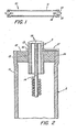
- FIG. 1 illustrates a high pressure discharge lamp tube assembly 10 incorporating one embodiment of the invention.
- the envelope of assembly 10 is a transparent ceramic tube 11.
- Each end of the tube 11 is sealed by a ceramic insert 12, each of which supports a cylindrical metal feedthrough 13.
- Niobium is the preferred metal because it is refractory, chemically compatible, and has a similar thermal coefficient to yttria and alumina.
- a tungsten electrode is positioned on one end of a feedthrough 13.
- Figure 2 represents a first end of the assembly showing in more detail the tube 11, insert 12, feedthrough 13, and electrode 14.
- the interface 15 between the insert 12 and feedthrough 13 is direct, without brazing or frit.
- insert 12 is made from a compressed mixture of fine ceramic powder (e.g., alumina or yttria) which is cold pressed or machined into a disc with an axial hole. Prior to heating the insert is in an unsintered or so-called "green" state. Upon sintering the volume of the insert 12 decreases with both its outside diameter and its inner diameter decreasing.
- fine ceramic powder e.g., alumina or yttria
- the dimensions of the unsintered insert are selected in relation to the inside diameter of the ceramic tube and the outside diameter of the feedthrough so that if the insert were to be sintered without being assembled with either the tube 11 or feedthrough 13, the sintered insert's 12 outside diameter would be 2 to 20% greater than the inside diameter of the sintered tube and the insert's inside diameter would be 2 to 20% less than the outside diameter of the feedthrough.
- the materials of the tube and insert are selected to have similar thermal expansion coefficients and to be chemically compatible. Both tube and insert may be of the same matrix material.
- the unsintered insert 12 is inserted in each end of the unsintered tube 11.
- the assembly is heated in an atmospheric furnace until both tube 11 and insert 12 are partially sintered. During sintering the diameter of tube 11 shrinks more than that of the insert 12. The tube 11 deforms slightly about the insert. As is known in the prior art, this procedure results in a bond at the tube- insert interface 16.
- the cylindrical niobium feedthrough 13 is positioned directly in the axial hole running through the insert 12 without brazing or frit.
- the feedthrough 13 is temporarily held in place by niobium wires and then the assembly is heated until both tube 11 and insert 12 are fully sintered.
- the diameter of the insert continues to contract during the sintering operation and the inner surface of the insert is forced against the feedthrough.
- the ceramic insert deforms at a lower flow stress than the niobium insert and so is deformed slightly and bulges out at the insert-feedthrough interface 15 forming thereby a brazeless, fritless hermetic seal at the interface. There appears to be both a mechanical and diffusion bond.
- the tube-insert-feedthrough assembly is heated at the temperature and time normally used to sinter the type of ceramic materials used for the tube and insert; which are about 1830°C for 2 hours for alumina, and 2150°C for 4 hours for yttria.
- Furnace atmosphere is selected not only for the ceramics, but to limit embrittlement of the niobium.
- Niobium after being heated to 2150°C for 1 hour has a hardness corresponding to atmosphere as follows: Vacuum 229 kg/mm 2 , dry Ar 385 kg/mm 2 , dry H 2 473 kg/mm , and wet H 2 563 kg/mm These values when compared with a value of 172 kg/mm2 for annealed Nb indicate that either vacuum or dry Ar furnace atmospheres are preferred, although hermetic seals may be made in a wet H 2 atmosphere.
- the feedthrough 13 has an axial hole into which the tungsten electrode 14 is inserted. One end of the tube is fitted with an electrode.
- the electrode 14 is welded to a niobium cap 18 which, in turn, is welded to the niobium insert 13.
- the tube 11 is then dosed with solid and gaseous fill materials.
- the other end is fitted with its corresponding electrode and welded closed completing the tube assembly 10.
- the direct niobium-to-ceramic seals allow the end temperature to be raised to the operating temperature limit of those materials.
- the temperature range 800-1200°C is now made available permitting many potential metal and metal halide fill ingredients to be considered.
Landscapes
- Engineering & Computer Science (AREA)
- Manufacturing & Machinery (AREA)
- Vessels And Coating Films For Discharge Lamps (AREA)
- Manufacture Of Electron Tubes, Discharge Lamp Vessels, Lead-In Wires, And The Like (AREA)
- Ceramic Products (AREA)
Applications Claiming Priority (2)
| Application Number | Priority Date | Filing Date | Title |
|---|---|---|---|
| US06/529,464 US4545799A (en) | 1983-09-06 | 1983-09-06 | Method of making direct seal between niobium and ceramics |
| US529464 | 1983-09-06 |
Publications (3)
| Publication Number | Publication Date |
|---|---|
| EP0136505A2 true EP0136505A2 (de) | 1985-04-10 |
| EP0136505A3 EP0136505A3 (en) | 1986-01-15 |
| EP0136505B1 EP0136505B1 (de) | 1988-11-02 |
Family
ID=24110029
Family Applications (1)
| Application Number | Title | Priority Date | Filing Date |
|---|---|---|---|
| EP84109837A Expired EP0136505B1 (de) | 1983-09-06 | 1984-08-17 | Direkte Versiegelung zwischen Niobium und Keramik |
Country Status (5)
| Country | Link |
|---|---|
| US (1) | US4545799A (de) |
| EP (1) | EP0136505B1 (de) |
| JP (1) | JPS6084761A (de) |
| CA (1) | CA1214491A (de) |
| DE (1) | DE3475029D1 (de) |
Cited By (7)
| Publication number | Priority date | Publication date | Assignee | Title |
|---|---|---|---|---|
| EP0175502B1 (de) * | 1984-08-31 | 1990-07-25 | Ngk Insulators, Ltd. | Entladungskolben für eine Hochdruckmetalldampfentladungslampe und Verfahren zu dessen Herstellung |
| EP0587238A1 (de) * | 1992-09-08 | 1994-03-16 | Koninklijke Philips Electronics N.V. | Hochdruckentladungslampe |
| EP0602530A3 (de) * | 1992-12-14 | 1995-01-04 | Patent Treuhand Ges Fuer Elektrische Gluehlampen Mbh | Verfahren zur Herstellung einer vakuumdichten Abdichtung zwischen einem keramischen und einem metallischen Partner, insbesondere für Entladungsgefässe und -lampen. |
| EP0887839A3 (de) * | 1997-06-27 | 1999-03-31 | Patent-Treuhand-Gesellschaft für elektrische Glühlampen mbH | Hochdruckentladungslampe mit keramischem Entladungsgefäss |
| EP1182681A1 (de) * | 2000-08-23 | 2002-02-27 | General Electric Company | Spritzgegossene Keramikbogenröhre zum Einsatz in einer Metallhalogenidlampe mit einem nicht-konischen Ende und zugehöriges Herstellungsverfahren |
| WO2002037531A1 (en) * | 2000-11-06 | 2002-05-10 | Koninklijke Philips Electronics N.V. | High-pressure discharge lamp |
| EP2073246A1 (de) * | 2007-12-21 | 2009-06-24 | Osram Sylvania, Inc. | Keramisches Entladungsgefäß mit Durchführung aus Molybdänlegierung |
Families Citing this family (53)
| Publication number | Priority date | Publication date | Assignee | Title |
|---|---|---|---|---|
| US4704093A (en) * | 1984-06-18 | 1987-11-03 | General Electric Company | High pressure sodium vapor lamp with improved ceramic arc tube |
| US4707636A (en) * | 1984-06-18 | 1987-11-17 | General Electric Company | High pressure sodium vapor lamp with PCA arc tube and end closures |
| JPS61284048A (ja) * | 1985-06-03 | 1986-12-15 | ジ−・テイ−・イ−・プロダクツ・コ−ポレイシヨン | セラミツク放電ランプ用高温度のテ−パ−状インリ−ド |
| ZA859137B (de) * | 1985-11-28 | 1986-06-16 | ||
| US4975620A (en) * | 1985-11-28 | 1990-12-04 | Iwasaki Electric Co., Ltd. | Metal vapor discharge lamp and method of producing the same |
| US4804889A (en) * | 1987-12-18 | 1989-02-14 | Gte Products Corporation | Electrode feedthrough assembly for arc discharge lamp |
| US5188554A (en) * | 1988-05-13 | 1993-02-23 | Gte Products Corporation | Method for isolating arc lamp lead-in from frit seal |
| DE68927594T2 (de) * | 1988-05-13 | 1997-07-24 | Gte Prod Corp | Bogenkolben für Hochdruckmetalldampfentladungslampen, Lampe mit einem solchen Kolben und Verfahren zur Herstellung |
| US5208509A (en) * | 1988-05-13 | 1993-05-04 | Gte Products Corporation | Arc tube for high pressure metal vapor discharge lamp |
| US5178808A (en) * | 1988-10-05 | 1993-01-12 | Makar Frank B | End seal manufacture for ceramic arc tubes |
| US5055361A (en) * | 1989-03-17 | 1991-10-08 | Gte Laboratories Incorporated | Bonded ceramic-metal article |
| US4883218A (en) * | 1989-03-17 | 1989-11-28 | Gte Laboratories Incorporated | Method of brazing a ceramic article to a metal article |
| US4883217A (en) * | 1989-03-17 | 1989-11-28 | Gte Laboratories Incorporated | Method of bonding a ceramic article to a metal article |
| US5057048A (en) * | 1989-10-23 | 1991-10-15 | Gte Laboratories Incorporated | Niobium-ceramic feedthrough assembly and ductility-preserving sealing process |
| EP0505472A1 (de) * | 1989-12-14 | 1992-09-30 | Gte Products Corporation | Verbindungsband für elektrodendurchführungsröhre für bogenentladungslampe |
| DE4127555A1 (de) * | 1991-08-20 | 1993-02-25 | Patent Treuhand Ges Fuer Elektrische Gluehlampen Mbh | Hochdruckentladungslampe |
| US5404078A (en) * | 1991-08-20 | 1995-04-04 | Patent-Treuhand-Gesellschaft Fur Elektrische Gluhlampen Mbh | High-pressure discharge lamp and method of manufacture |
| DE9112690U1 (de) * | 1991-10-11 | 1991-12-05 | Patent-Treuhand-Gesellschaft für elektrische Glühlampen mbH, 8000 München | Hochdruckentladungslampe |
| DE9207816U1 (de) * | 1992-06-10 | 1992-08-20 | Patent-Treuhand-Gesellschaft für elektrische Glühlampen mbH, 8000 München | Hochdruckentladungslampe |
| US5426343A (en) * | 1992-09-16 | 1995-06-20 | Gte Products Corporation | Sealing members for alumina arc tubes and method of making the same |
| EP0609477B1 (de) * | 1993-02-05 | 1999-05-06 | Patent-Treuhand-Gesellschaft für elektrische Glühlampen mbH | Keramisches Entladungsgefäss für Hochdruckentladungslampe und Herstellungsverfahren derselben und damit verbundene Dichtungsmaterialien |
| US5621275A (en) * | 1995-08-01 | 1997-04-15 | Osram Sylvania Inc. | Arc tube for electrodeless lamp |
| US5592048A (en) * | 1995-08-18 | 1997-01-07 | Osram Sylvania Inc. | Arc tube electrodeless high pressure sodium lamp |
| US6126889A (en) * | 1998-02-11 | 2000-10-03 | General Electric Company | Process of preparing monolithic seal for sapphire CMH lamp |
| US6004503A (en) * | 1998-10-02 | 1999-12-21 | Osram Sylvania Inc. | Method of making a ceramic arc tube for metal halide lamps |
| US6346495B1 (en) * | 1999-12-30 | 2002-02-12 | General Electric Company | Die pressing arctube bodies |
| US7132797B2 (en) * | 2002-12-18 | 2006-11-07 | General Electric Company | Hermetical end-to-end sealing techniques and lamp having uniquely sealed components |
| US7215081B2 (en) * | 2002-12-18 | 2007-05-08 | General Electric Company | HID lamp having material free dosing tube seal |
| US7839089B2 (en) * | 2002-12-18 | 2010-11-23 | General Electric Company | Hermetical lamp sealing techniques and lamp having uniquely sealed components |
| JP3953431B2 (ja) * | 2003-03-10 | 2007-08-08 | 日本碍子株式会社 | 高圧放電灯用発光容器および高圧放電灯 |
| WO2004086443A1 (ja) * | 2003-03-27 | 2004-10-07 | Matsushita Electric Industrial Co., Ltd. | 高圧放電ランプの製造方法、この製造方法を用いて製造された高圧放電ランプ、ランプユニットおよび画像表示装置 |
| WO2005055269A2 (en) * | 2003-12-01 | 2005-06-16 | Mbda Uk Limited | Improvements in or relating to an electron gun and an electron beam window |
| CN1969366B (zh) * | 2004-06-14 | 2011-06-08 | 皇家飞利浦电子股份有限公司 | 陶瓷金属卤化物放电灯 |
| US7358666B2 (en) * | 2004-09-29 | 2008-04-15 | General Electric Company | System and method for sealing high intensity discharge lamps |
| US7432657B2 (en) * | 2005-06-30 | 2008-10-07 | General Electric Company | Ceramic lamp having shielded niobium end cap and systems and methods therewith |
| US7852006B2 (en) | 2005-06-30 | 2010-12-14 | General Electric Company | Ceramic lamp having molybdenum-rhenium end cap and systems and methods therewith |
| US7615929B2 (en) | 2005-06-30 | 2009-11-10 | General Electric Company | Ceramic lamps and methods of making same |
| US7378799B2 (en) * | 2005-11-29 | 2008-05-27 | General Electric Company | High intensity discharge lamp having compliant seal |
| DE102005058895A1 (de) * | 2005-12-09 | 2007-06-14 | Patent-Treuhand-Gesellschaft für elektrische Glühlampen mbH | Metallhalogenidlampe |
| US20090212704A1 (en) * | 2008-02-27 | 2009-08-27 | Osram Sylvania Inc. | Ceramic discharge vessel with chromium-coated niobium feedthrough and discharge lamp containing same |
| US9163883B2 (en) | 2009-03-06 | 2015-10-20 | Kevlin Thermal Technologies, Inc. | Flexible thermal ground plane and manufacturing the same |
| US20110177747A1 (en) * | 2010-01-21 | 2011-07-21 | Thomas Patrician | Method of Making a Fritless Seal in a Ceramic Arc Tube for a Discharge Lamp |
| EP2880678A2 (de) | 2012-08-03 | 2015-06-10 | Koninklijke Philips N.V. | Hochdruckentladungslampe mit einem uv-verstärker und herstellungsverfahren dafür |
| US12523431B2 (en) * | 2014-09-15 | 2026-01-13 | Kelvin Thermal Technologies, Inc. | Polymer-based microfabricated thermal ground plane |
| US11988453B2 (en) | 2014-09-17 | 2024-05-21 | Kelvin Thermal Technologies, Inc. | Thermal management planes |
| US11598594B2 (en) | 2014-09-17 | 2023-03-07 | The Regents Of The University Of Colorado | Micropillar-enabled thermal ground plane |
| CN106794562B (zh) * | 2014-09-17 | 2019-07-23 | 科罗拉多州立大学董事会法人团体 | 启用微柱的热接地平面 |
| US12385697B2 (en) | 2014-09-17 | 2025-08-12 | Kelvin Thermal Technologies, Inc. | Micropillar-enabled thermal ground plane |
| US12104856B2 (en) | 2016-10-19 | 2024-10-01 | Kelvin Thermal Technologies, Inc. | Method and device for optimization of vapor transport in a thermal ground plane using void space in mobile systems |
| CN110192273B (zh) | 2016-11-08 | 2023-07-28 | 开尔文热技术股份有限公司 | 用于在热接地平面中散布高热通量的方法和设备 |
| WO2018208801A1 (en) | 2017-05-08 | 2018-11-15 | Kelvin Thermal Technologies, Inc. | Thermal management planes |
| DE212019000445U1 (de) | 2018-12-11 | 2021-08-17 | Kelvin Thermal Technologies | Dampfkammer |
| US12464679B2 (en) | 2020-06-19 | 2025-11-04 | Kelvin Thermal Technologies, Inc. | Folding thermal ground plane |
Family Cites Families (16)
| Publication number | Priority date | Publication date | Assignee | Title |
|---|---|---|---|---|
| US2561520A (en) * | 1940-03-27 | 1951-07-24 | Hartford Nat Bank & Trust Co | Vacuumtight seal for electrical apparatus and method of forming such seals |
| DE866371C (de) * | 1941-03-08 | 1953-02-09 | Patra Patent Treuhand | Verfahren zur Herstellung von Hochdruckentladungslampen aus Quarzglas |
| US2699594A (en) * | 1952-02-27 | 1955-01-18 | Sylvania Electric Prod | Method of assembling semiconductor units |
| US3035372A (en) * | 1957-04-05 | 1962-05-22 | Philips Electronic Pharma | Method for making a glass to metal seal |
| US3281309A (en) * | 1961-12-12 | 1966-10-25 | Gen Electric | Ceramic bonding |
| GB1107764A (en) * | 1965-01-07 | 1968-03-27 | Gen Electric Co Ltd | Improvements in or relating to the closure of tubes of refractory oxide material |
| US4004173A (en) * | 1965-12-27 | 1977-01-18 | Sydney Alfred Richard Rigden | Niobium alumina sealing and product produced thereby |
| US3441421A (en) * | 1966-10-24 | 1969-04-29 | Gen Electric | Calcia-magnesia-alumina seal compositions |
| US3448319A (en) * | 1966-10-31 | 1969-06-03 | Gen Electric | Niobium end seal |
| DE1923138B2 (de) * | 1968-05-17 | 1973-07-19 | Corning, Glass Works, Corning, N Y V St A ) | Verfahren zur herstellung einer hermetischen verbindung wenigstens zweier polykristalliner koerper aus al tief 2 o tief 3 |
| US3564328A (en) * | 1968-07-29 | 1971-02-16 | Corning Glass Works | Ceramic articles and method of fabrication |
| GB1196899A (en) * | 1969-04-18 | 1970-07-01 | Thorn Lighting Ltd Formerly Kn | Seals between Sintered Ceramic Parts |
| US3872859A (en) * | 1973-04-04 | 1975-03-25 | Sono Therapy Inst Inc | Method and device for stimulating the organs associated with the human scalp |
| JPS5928942B2 (ja) * | 1974-04-10 | 1984-07-17 | 株式会社日立製作所 | 熱的異方性部材よりなる容器 |
| NL7511416A (nl) * | 1975-09-29 | 1977-03-31 | Philips Nv | Elektrische ontladingslamp. |
| JPS5517466A (en) * | 1978-07-24 | 1980-02-06 | Nissin High Voltage Co Ltd | Particle beam irradiator |
-
1983
- 1983-09-06 US US06/529,464 patent/US4545799A/en not_active Expired - Lifetime
-
1984
- 1984-08-17 DE DE8484109837T patent/DE3475029D1/de not_active Expired
- 1984-08-17 EP EP84109837A patent/EP0136505B1/de not_active Expired
- 1984-09-05 JP JP59184729A patent/JPS6084761A/ja active Granted
- 1984-09-05 CA CA000462497A patent/CA1214491A/en not_active Expired
Cited By (9)
| Publication number | Priority date | Publication date | Assignee | Title |
|---|---|---|---|---|
| EP0175502B1 (de) * | 1984-08-31 | 1990-07-25 | Ngk Insulators, Ltd. | Entladungskolben für eine Hochdruckmetalldampfentladungslampe und Verfahren zu dessen Herstellung |
| EP0587238A1 (de) * | 1992-09-08 | 1994-03-16 | Koninklijke Philips Electronics N.V. | Hochdruckentladungslampe |
| EP0602530A3 (de) * | 1992-12-14 | 1995-01-04 | Patent Treuhand Ges Fuer Elektrische Gluehlampen Mbh | Verfahren zur Herstellung einer vakuumdichten Abdichtung zwischen einem keramischen und einem metallischen Partner, insbesondere für Entladungsgefässe und -lampen. |
| EP0887839A3 (de) * | 1997-06-27 | 1999-03-31 | Patent-Treuhand-Gesellschaft für elektrische Glühlampen mbH | Hochdruckentladungslampe mit keramischem Entladungsgefäss |
| US6181065B1 (en) | 1997-06-27 | 2001-01-30 | Patent-Treuhand-Gesellschaft F. Elektrische Gluehlampen Mbh | Metal halide or sodium high pressure lamp with cermet of alumina, molybdenum and tungsten |
| EP1182681A1 (de) * | 2000-08-23 | 2002-02-27 | General Electric Company | Spritzgegossene Keramikbogenröhre zum Einsatz in einer Metallhalogenidlampe mit einem nicht-konischen Ende und zugehöriges Herstellungsverfahren |
| WO2002037531A1 (en) * | 2000-11-06 | 2002-05-10 | Koninklijke Philips Electronics N.V. | High-pressure discharge lamp |
| EP2073246A1 (de) * | 2007-12-21 | 2009-06-24 | Osram Sylvania, Inc. | Keramisches Entladungsgefäß mit Durchführung aus Molybdänlegierung |
| US7710038B2 (en) | 2007-12-21 | 2010-05-04 | Osram Sylvania Inc. | Ceramic discharge vessel having molybdenum alloy feedthrough |
Also Published As
| Publication number | Publication date |
|---|---|
| CA1214491A (en) | 1986-11-25 |
| JPS6084761A (ja) | 1985-05-14 |
| JPH0542769B2 (de) | 1993-06-29 |
| DE3475029D1 (en) | 1988-12-08 |
| EP0136505A3 (en) | 1986-01-15 |
| EP0136505B1 (de) | 1988-11-02 |
| US4545799A (en) | 1985-10-08 |
Similar Documents
| Publication | Publication Date | Title |
|---|---|---|
| US4545799A (en) | Method of making direct seal between niobium and ceramics | |
| US5075587A (en) | High-pressure metal vapor discharge lamp, and method of its manufacture | |
| US5404078A (en) | High-pressure discharge lamp and method of manufacture | |
| US5426343A (en) | Sealing members for alumina arc tubes and method of making the same | |
| US5810635A (en) | High-pressure discharge lamp, method of its manufacture, and sealing material used with the method and the resulting lamp | |
| US6528945B2 (en) | Seal for ceramic metal halide discharge lamp | |
| JPS6213792B1 (de) | ||
| US4160930A (en) | Electric discharge lamp with annular current conductor | |
| JP2001058882A (ja) | 接合体、高圧放電灯およびその製造方法 | |
| JP2008124037A (ja) | 高圧放電ランプ | |
| JP2004356098A (ja) | モリブデン電極を備える冷陰極蛍光ランプ | |
| US5057048A (en) | Niobium-ceramic feedthrough assembly and ductility-preserving sealing process | |
| JP4772050B2 (ja) | セラミックメタルハライド放電ランプ | |
| US5198722A (en) | High-pressure discharge lamp with end seal evaporation barrier | |
| US7741780B2 (en) | Ceramic discharge vessel having a sealing composition | |
| US5095246A (en) | Niobium-ceramic feedthrough assembly | |
| EP1146537B1 (de) | Hochdruckbogenentladungslampenröhre und deren herstellungsverfahren | |
| JP2002326878A (ja) | 接合体および高圧放電灯 | |
| EP0341749B1 (de) | Bogenkolben für Hochdruckmetalldampfentladungslampen, Lampe mit einem solchen Kolben und Verfahren zur Herstellung | |
| JP5264057B2 (ja) | タングステン合金製フィードスルーを有するセラミック放電容器 | |
| US5188554A (en) | Method for isolating arc lamp lead-in from frit seal | |
| US8299709B2 (en) | Lamp having axially and radially graded structure | |
| JP3462458B2 (ja) | 高圧放電灯およびその製造方法 | |
| JP2001283778A (ja) | 金属蒸気放電灯 | |
| JPS62243235A (ja) | 高圧ナトリウムランプ |
Legal Events
| Date | Code | Title | Description |
|---|---|---|---|
| PUAI | Public reference made under article 153(3) epc to a published international application that has entered the european phase |
Free format text: ORIGINAL CODE: 0009012 |
|
| 17P | Request for examination filed |
Effective date: 19840817 |
|
| AK | Designated contracting states |
Designated state(s): DE FR GB NL |
|
| PUAL | Search report despatched |
Free format text: ORIGINAL CODE: 0009013 |
|
| AK | Designated contracting states |
Designated state(s): DE FR GB NL |
|
| 17Q | First examination report despatched |
Effective date: 19870514 |
|
| GRAA | (expected) grant |
Free format text: ORIGINAL CODE: 0009210 |
|
| AK | Designated contracting states |
Kind code of ref document: B1 Designated state(s): DE FR GB NL |
|
| REF | Corresponds to: |
Ref document number: 3475029 Country of ref document: DE Date of ref document: 19881208 |
|
| EN | Fr: translation not filed | ||
| PLBE | No opposition filed within time limit |
Free format text: ORIGINAL CODE: 0009261 |
|
| STAA | Information on the status of an ep patent application or granted ep patent |
Free format text: STATUS: NO OPPOSITION FILED WITHIN TIME LIMIT |
|
| 26N | No opposition filed | ||
| PGFP | Annual fee paid to national office [announced via postgrant information from national office to epo] |
Ref country code: GB Payment date: 19920817 Year of fee payment: 9 |
|
| PGFP | Annual fee paid to national office [announced via postgrant information from national office to epo] |
Ref country code: FR Payment date: 19920827 Year of fee payment: 9 |
|
| PGFP | Annual fee paid to national office [announced via postgrant information from national office to epo] |
Ref country code: NL Payment date: 19920831 Year of fee payment: 9 |
|
| PGFP | Annual fee paid to national office [announced via postgrant information from national office to epo] |
Ref country code: DE Payment date: 19920930 Year of fee payment: 9 |
|
| REG | Reference to a national code |
Ref country code: FR Ref legal event code: TP |
|
| NLS | Nl: assignments of ep-patents |
Owner name: GTE PRODUCTS CORPORATION TE DANVERS, MASSACHUSETTS |
|
| PG25 | Lapsed in a contracting state [announced via postgrant information from national office to epo] |
Ref country code: GB Effective date: 19930817 |
|
| PG25 | Lapsed in a contracting state [announced via postgrant information from national office to epo] |
Ref country code: NL Effective date: 19940301 |
|
| GBPC | Gb: european patent ceased through non-payment of renewal fee |
Effective date: 19930817 |
|
| NLV4 | Nl: lapsed or anulled due to non-payment of the annual fee | ||
| PG25 | Lapsed in a contracting state [announced via postgrant information from national office to epo] |
Ref country code: FR Effective date: 19940429 |
|
| PG25 | Lapsed in a contracting state [announced via postgrant information from national office to epo] |
Ref country code: DE Effective date: 19940503 |
|
| REG | Reference to a national code |
Ref country code: FR Ref legal event code: ST |