EP0136604B1 - Dekodierverfahren und Vorrichtung dafür. - Google Patents
Dekodierverfahren und Vorrichtung dafür. Download PDFInfo
- Publication number
- EP0136604B1 EP0136604B1 EP84110958A EP84110958A EP0136604B1 EP 0136604 B1 EP0136604 B1 EP 0136604B1 EP 84110958 A EP84110958 A EP 84110958A EP 84110958 A EP84110958 A EP 84110958A EP 0136604 B1 EP0136604 B1 EP 0136604B1
- Authority
- EP
- European Patent Office
- Prior art keywords
- error
- decoding
- column
- decoding mode
- flags
- Prior art date
- Legal status (The legal status is an assumption and is not a legal conclusion. Google has not performed a legal analysis and makes no representation as to the accuracy of the status listed.)
- Expired
Links
- 238000000034 method Methods 0.000 title claims description 69
- 238000012937 correction Methods 0.000 claims description 51
- 238000001514 detection method Methods 0.000 claims description 40
- 239000011159 matrix material Substances 0.000 claims description 16
- 238000010586 diagram Methods 0.000 description 10
- 230000005540 biological transmission Effects 0.000 description 6
- 150000001875 compounds Chemical class 0.000 description 6
- 230000003287 optical effect Effects 0.000 description 3
- 230000001419 dependent effect Effects 0.000 description 2
- 238000010276 construction Methods 0.000 description 1
- 238000003672 processing method Methods 0.000 description 1
Images




Classifications
-
- H—ELECTRICITY
- H03—ELECTRONIC CIRCUITRY
- H03M—CODING; DECODING; CODE CONVERSION IN GENERAL
- H03M13/00—Coding, decoding or code conversion, for error detection or error correction; Coding theory basic assumptions; Coding bounds; Error probability evaluation methods; Channel models; Simulation or testing of codes
- H03M13/29—Coding, decoding or code conversion, for error detection or error correction; Coding theory basic assumptions; Coding bounds; Error probability evaluation methods; Channel models; Simulation or testing of codes combining two or more codes or code structures, e.g. product codes, generalised product codes, concatenated codes, inner and outer codes
-
- G—PHYSICS
- G11—INFORMATION STORAGE
- G11B—INFORMATION STORAGE BASED ON RELATIVE MOVEMENT BETWEEN RECORD CARRIER AND TRANSDUCER
- G11B20/00—Signal processing not specific to the method of recording or reproducing; Circuits therefor
- G11B20/10—Digital recording or reproducing
- G11B20/18—Error detection or correction; Testing, e.g. of drop-outs
- G11B20/1833—Error detection or correction; Testing, e.g. of drop-outs by adding special lists or symbols to the coded information
Definitions
- the present invention relates generally to a decoding method and system, and particularly to a decoding system capable of high speed decoding suitable for use in parity checking in digital information data transmission or recording with high reliability.
- a data sequence is blocked into blocked data of a predetermined length, and coding is performed for each blocked data.
- a reliability and error characteristic of the transmission line or recording medium is not sufficient, there is a need to correct compound error wherein random error and burst error may exist together. Then, by randomizing the burst error into random error by means of interleaving the random errors are corrected.
- the object of error correction is only the random errors, or the compound errors, higher error correction capability for random errors contribute to higher reliability of digital information data.
- a product code has a characteristic that decoding the component code is easy with respect to its correction capability, and is good in harmonizing with the interleaving for correction of the compound error. Therefore the product code is being used more often for error correction in the system of transmission or recording of digital information data.
- the code comprised of two or more component codes such as the product code
- it is necessary that decodings of the component codes of the code must organically cooperate. For instance, in decoding of a product code constituted by two component codes, such repeated operation becomes necessary that after decoding a first component code, decoding a second component code is carried out by utilizing the result of the first decoding, and when necessary, decoding the first component code is repeated.
- distances Hamming distances between the received sequence including error and the correct code word are calculated, and it is assumed that the nearest code to the received sequence is the true code, thereby replacing the error code by the true code. If two or more of the nearest code words exist, error correction cannot performed and the error correction circuit detects the error.
- distance between the code words is the most important parameter. and especially the minimum distance of all distances, namely t of the present invention, is the parameter to determine the ability of correction for this code.
- the distance from the code word means number of errors from that, and the code of the minimum distance t means that none of the code words becomes to other code words unless more than t errors occur. Also, it may happen that changing to other code word does not occur in spite of occurrence of more than t errors. That is, there exist many cases depending on many error patterns. Therefore, a distance to the nearest code word (i.e. number of apparent errors) is not determined.
- correct operation is performed only at the time when errors of less than ⁇ (t-1)/2 ⁇ occur in the code word in the correction circuit that the minimum distance is t. But, when more than ⁇ (t-1)/2 ⁇ errors occur, correct operation is not guaranteed. That is, when more than ⁇ (t-1)/2 ⁇ errors occur, both the nearest code word to the received sequence and the distance (number of errors) to this code word are not determined. If it happens that the distance to a non-corresponding code word becomes less than ⁇ (t-1)/2 ⁇ . wrong correction is made to the code word, and if there are two or more code words of the nearest, such a state is detected that correction can not be performed. It is dependent upon the error pattern that which state is selected.
- the object of the present invention is to provide a decoding system capable of high speed decoding of a product code of minimum distance 2t constituted with two codes with minimum distance 2 and minimum distance t, wherein, with respect to information of (kxl) symbols arranged in a matrix with k rows and l columns, in each row a checksum symbol of l symbols is added for constituting code with minimum distance 2, and in each of (l+1) columns including a column for said added checksum symbols a set of parity check symbols are added for constituting a code with minimum distance t.
- the decoding system in accordance with the present invention performs a first decoding of (l+1)column codes in column direction by a first decoder, and then a deciding on the decoding mode among three decoding modes by statistical processing of the error number flags issued from the first decoder, and finally a second decoding in which, responding to the decided decoding mode, the decoding is made as assertion of simple error detection, or single erasure error correction by using row codes, or error detection by using codes in row direction.
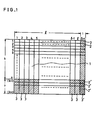
- FIG. 1 is a diagram showing principle of constitution of a product code to which the decoding system in accordance with the present invention is applied.
- FIG. 2 is a flow chart showing process of decoding in the decoding system in accordance with the present invention.
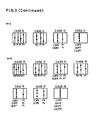
- FIG. 3 is a set of schematical diagrams showing error corrections of various kinds in the decoding system in accordance with the present invention.
- FIG. 4 is a block diagram showing one embodiment of the decoding system in accordance with the present invention.
- FIG. 5 is a block diagram of an inner code decoder 4 of FIG. 4.
- FIG. 6(a) is a block diagram showing an example of error number flag counter 7 of FIG. 4.
- FIG. 6(b) is a waveform diagram showing waveform of input signal to the error number flag counter of FIG. 6(a).
- FIG. 7 is a circuit diagram showing one example of circuit configuration of a pointer generator 9 of the decoding system of FIG. 4.
- FIG. 8 is a circuit block diagram of another embodiment in accordance with the present invention.
- FIG. 1 is a diagram showing a construction of a product code to which the present invention is applied.
- the information data 1 are disposed in a matrix having k rows and l columns.
- the component elements of the matrix are referred to as symbols here, wherein one above-mentioned symbol is represented by i-bit tuple.
- the checksum symbols 2 are obtained by performing exclusive ORs between respective i-bit elements of l symbols in each row of the matrix. Then, the next coding is made with respect to each column of the matrix comprising the symbols (k x [l+1]) for making a column code of minimum distance t, and parity check symbols 3 consisting of r symbols are added to each of the (l+1) columns, thereby obtaining rows of distance(k+r) symbols.
- the matrix having ([k+r] x [l+1]) becomes a product code having minimum distance 2t.
- parity check symbols 3' for each of the r symbols are added to the (l+1)-th column to constitute checksum symbols 2' for the (k+1)-th row through (k+r)-th row.
- the order of coding between the rows and the columns does not limit the gist of the invention.
- coding in rows is referred to as outer code and coding in columns are referred to as inner code; but these namings are not limited to the above-mentioned,and may be interchanged.
- Decoding of the product code in accordance with the decoding system embodying the present invention is carried out along the process shown in a decoding flow chart of FIG. 2.
- a decoding process is carried out for the inner codes. Error number flags are issued as a result of the decoding of the inner codes.
- error correction can be made for or less and error detection can be made for or more, wherein the expression ⁇ x ⁇ represents a largest integer which is equal to or less than x.
- the below-mentioned error number flags Fi are set.
- error number flags Fi are counted for each of the error numbers. Provided that a number of occurrences of error number flags Fi is Ci, then the following equation (1) holds The above-mentioned statistical processing and subsequent processing are elucidated.
- This decoding is referred to as the first type decoding method.
- a pointer is put on a column of the inner code whereat an error number flag Fi for the Ci of the highest priority order in non-zero Ci's is 1. Then, (k+r) pieces of checksums are obtained by making exclusive-OR operation between every corresponding bits of the (l+1) symbols of each row which are outer codes of the received sequence or the read out sequence, and each of the checksums is added to the column, on which the pointer is put, through the exclusive-OR operation. Alternatively, the checksum of the outer codes of respective rows except the column on which the pointer is put is obtained, and the resultant checksum is substituted in place of the column on which the pointer is put.
- (k+r) pieces of checksums are obtained by making exclusive-OR operation between every corresponding bits of the (l+1) symbols of each row which are outer codes of the received sequence or the read out sequence.
- a pointer is put on a column of the inner code whereat an error number flag Fi for the Ci of the highest priority order in non-zero Ci's is 1. Then, (k+r) pieces of checksums are obtained by making exclusive-OR operation between every corresponding bits of the (l+1) symbols of each row which are outer codes of the received sequence or the read out sequence, and each of the checksums is added to the column, on which the pointer is put, through the exclusive-OR operation. Alternatively, the checksum of the outer codes of respective rows except the column on which the pointer is put is obtained, and the resultant checksum is substituted in place of the column on which the pointer is put.
- (k+r) pieces of checksums are obtained by making exclusive-OR operation between every corresponding bits of the (l+1) symbols of each row which are outer codes of the received sequence or the read out sequence.
- This second type decoding method can be considered as a method which is simplified to the utmost extent from the first type decoding method.
- the first type decoding method in classifying of the decoding mode, all of Fi for i within the range of is noted; while in the second type decoding method, in classifying of the decoding mode,only one error number flag is noted.
- a third type decoding method which is intermediate between the first type decoding method and the second type decoding method, wherein, for instance, in classifying of the decoding mode two error number flags are noticed or three error number flags and are noticed, and so on, may be considered.
- the intermediate method naturally has a performance more close to the first type decoding method rather than the second type decoding method.
- error number flags to be noted is not of a consecutive priority order, for instance, a method to note appearance of and F1, but such method has lower performance in at least random error correction capability in comparison with the method noticing occurrences of .
- FIG. 3 shows patterns for all cases of errors of 5 or less symbols.
- cases are classified by error number e occurring in the whole of the product code and further by error numbers of inner code in respective colums.
- the error number flags generated by decoding of the inner code are shown at the position below the respective columns.
- the decoding mode III is for detecting whether the error is appropriately corrected or not using the inner code, and detection of an uncorrectable errors are asserted only for the CASEs 16 (iii) 17 (ii) and 18(iv).
- classification becomes as follows.
- each of the CASEs classified into the decoding mode II it is different from the decoding mode II of the first type decoding method that the error always remains in the column on which the pointer is put, whereas other columns except the column on which the pointer is put are corrected. Since non-corrected column is only one on which the pointer is put, this column can be also corrected by process of the erasure error correction using the outer code.
- This third type decoding method which is an intermediate decoding method between the first type decoding method and the second type decoding method, a decoding method noticing the occurrence of two error number flags of and is considered.
- This third type decoding method also has the following three decoding modes.
- FIG. 4 is a block diagram of the actual embodiment of the decoding system in accordance with the present invention.
- An input signal to this decoding system is a product code which has been transmitted or recorded in the direction of the row, that is, in the direction of outer codes which are sequentially received or reproduced is inputted.
- the input information data are firstly stored in a memory in the form of a matrix shown in FIG. 1, and the information data are sequentially read out in the direction of columns and input as the input signal 101 to the inner code decoder, wherein decoding of the inner code is carried out for (k+r) symbols in every column. Then the decoded sequence data 102 are stored in a temporary memory 6.
- the checksum generator 5 receives the decoded data sequence 102 and generates a checksum signal for each row.
- checksum symbols 103 which are obtained through exclusive OR operation of (l+1) symbols at every row, are completed.
- the inner code decoder 4 issues error number flags 104 upon decoding of the inner code.
- the error number flag counter 7 counts error number flags 104 in every class and sends the occurrence number data 105 of the error number flags to the decoding mode decision circuit 8 upon completion of the decoding of the input sequence data 101 having [l+1] x [k+r] symbols by the inner decoder 4.
- the decoding mode decision circuit 8 decides the decoding modes corresponding to the occurrence number data 105 of the error number flags.
- the decoding mode decision circuit 8 will determine a decoding mode as one of the aforementioned first type decoding method, second type decoding method or third type decoding method.
- the error detection flag generator 11 issues uncorrectable error detection flag 106 to the output terminal.
- a zero criterion circuit 10 decides whether the checksum data 103 is zero or non-zero, and if the decision result is zero a no error condition in the temporary memory 6 is determined. At this time, the data contents of the temporary memory 6 are issued as the output data sequence 107 to the external output terminal. On the other hand, when the decision result is not zero, the zero decision circuit 10 issues a signal to cause an error detection flag generator 11 to issue an uncorrectable error detection flag 106 to the output circuit.
- each content of (k+r) pieces of symbols of the column which is designated by the pointer determined in the pointer generation circuit 9 by the error number flags 104, is transmitted to the checksum generator 5 by means of the temporary memory 6, and the content of the symbols is added to the content of the corresponding symbols to checksums of respective rows through the exclusive OR operation.
- the resultant EX-OR data are stored in the temporary memory at the address designated by the pointer 108, and thereafter the contents of the temporary memory are issued as the output data sequence 107 to the external output terminal.
- the inner decoder 4 can be schematically represented as shown in FIG. 5.
- the input sequence 101 is input to a sequential buffer 401 and error enumerator 402, and the error enumerator 402 issues error position and error value of the codeword upon every completion of input of code word of one inner code.
- the error enumerator 402 issues a number of errors occurring in the codeword as the error number flags 104 (comprising
- the correction unit 405 performs error correction against an input data sequence 101 of one codeword stored in the buffer memory 401, and issues a decoded data sequence 102.
- the most important process in the decoding system of the present invention is the determination of the decoding mode through statistical processing of the error number flags.
- one practical example to carry out the statistical processing of the error number flags for the product code having the minimum distance 10 is described.
- FIG. 6a shows one example of the error number flag counter 7 for the error number flag Fi.
- This circuit is provided respectively to count the occurrences of each of the error number flag outputs of error enumerator 402 shown in FIG. 5.
- the circuit shown in FIG. 6a counts the error number.
- the number Ci of the occurrences of Fi are decided as shown in the following truth table.
- the decoding mode decision circuit 8 decides the decoding mode using the following logic.
- the decoding mode I, decoding mode II and decoding mode III are represented respectively by M1, M2 and M3.
- the decoding mode decision circuit 8 can be realized by combinations of simple AND and OR logic circuits.
- an address latch signal generating circuit which is a main part of the pointer generator 9 is elucidated with reference to FIG. 7
- the pointer is necessary only when the case is the decoding mode II, and the decoding mode is not determined until completion of the decoding of (l+1) inner codes. Therefore, a provisional pointer is put on the inner code allowing the possibility of the pointer being put on, and when error number flags of higher priority order arise , the provisional pointer is revised.
- Fig. 7 is an example of an actual circuit of the pointer generation circuit.
- the circuit has three D-flip-flops 121, 122 and 123, output terminals which are connected to a 4-bit cascadeable priority register 13(SN74278, made by TEXAS Instrument Inc.) , and the D-flip-flops 121, 122 and 123 are cleared up by initial clear signal and set by the error number flags initially input thereto.
- the error number flags F1, F2 and F3 are input to the D-flip-flops 121, 122 and 123, respectively, and the outputs from the flip-flops 121, 122 and 123 are input to the 4-bit cascadeable priority register 13 in the priority order of the error number flags.
- the register 13 changes its output only when an input of a higher priority order is inputted thereto.
- Output signals of the 4-bit cascadeable priority register 13 are given to the D-flip-flops 141, 142 and 143 and also to the HAND gates 151, 152 and 153, which when the output of the register 13 is changed from L-level to H-level, issue a short pulse.
- the short pulse is given to the AND gate 16, which accordingly issues output short signal PNT only when error number flag of higher priority order firstly arises.
- the address of the temporary memory 6 to which the decoded sequence 102 is temporarily stored is latched.
- the address of the temporary memory 6 which is latched by the last generated output PNT becomes a candidate of the pointer, and when the case is decided to be the decoding mode II, the latched address becomes the real pointer.
- the error number flag to be noted is only F3, and accordingly the pointer generation circuit 9 can become simple as shown in FIG. 8.
- Optical information recording/reproducing apparatus or the like does not necessarily have satisfactory reliability, and there is inherent error characteristics in its recording medium. Accordingly, there is a severe demand to correct compound errors wherein random errors and burst errors should exist mixed together. Accordingly, in order to obtain error correction of the optical recording/reproducing apparatus, the product codes on which the decoding system in accordance with the present invention is applicable is very suitable. For instance, a case where a sector of error correction unit consists of 525 bytes which is the total of 512 bytes user data and 13 byte control data is considered.
- the control data is that which is to be used in sector identification or file identification or sector management by the optical information recording/reproducing apparatus, and for instance, this is data which is not accessible to users.
- the 525 bytes of data to be decoded is considered by symbol units of 4-bit symbols, and 1050 symbols are arranged to be represented by a matrix of 10 rows and 105 columns.
- 1050 symbols are arranged to be represented by a matrix of 10 rows and 105 columns.
- checksums of 105 symbols are obtained, and the resultant checksums are added to the right ends, namely, at the 106 columns as the checksum symbols.
- the codings are made with a Reed-Solomon code of code length 15, information symbol number 10 and minimum distance 6 defined on Galois field (GF(24)) wherein generator polynominal G(x) of the Reed-Solomon is given
- G(x) Galois field
- the data to be recorded are coded into a product code with minimum distance 12 represented by a matrix of (15 x 106).
- the coded data are stored in the direction of the row, and the stored coded data are decoded by using the aforementioned first decoding method in accordance with the present invention, random errors in the sectors until five symbols are completely corrected, and in the view point of probability the random errors until 212 symbols can be corrected.
- compound errors consisting of, for instance, one burst error of 212 symbol length and one random error, or consisting of one burnt error of 106 symbol length and any three symbol random error can be corrected.
- the decoding system of the product code in accordance with the present invention has rather simple decoding procedure and the decoding is completed by sequential decoding of two kinds of code, the configuration is simple and high speed operation is possible. Transmission or recording reproducing of digital information data at high speed and with high reliability is possible and the system has a great industrial utility.
Landscapes
- Engineering & Computer Science (AREA)
- Physics & Mathematics (AREA)
- Probability & Statistics with Applications (AREA)
- Theoretical Computer Science (AREA)
- Signal Processing (AREA)
- Error Detection And Correction (AREA)
Claims (7)
- Decodiersystem für einen Produktcode mit Minimalabstand 2t, bei dem in bezug auf eine Information von in einer Matrix mit k Reihen und ℓ Spalten angeordneten (k x ℓ) Symbolen, wobei jedes Symbol aus einer vorbestimmten Anzahl von Bits besteht,- zu jeder der k Reihen ein Kontrollzahl-Symbol zu den ℓ Symbolen addiert wird, wobei Reihencodes mit Minimalabstand 2 gebildet werden, und- zu jeder der (ℓ + 1) Spalten einschließlich der Spalte für die addierte Kontrollzahl Symbole r Kontrollsymbole zu k Symbolen addiert werden, wobei Spaltencodes mit Minimalabstand (t) gebildet sind,wobei das Decodiersystem umfaßt:- einen ersten Decodierer (4) zum Decodieren von (ℓ + 1) Spaltencodes mit Minimalabstand t in der Spaltenrichtung zur Erfassung von Fehlern und zur Korrektur von bis zu
 - einen Fehlerzahlflag-Zähler (7) zur Klassifizierung von von dem ersten Decodierer (4) ausgegebenen, ankommenden ℓ + 1 Fehlerzahlflags (104) in {(t - 1) / 2} + 2 Klassen und zum Zählen der Fehlerzahlflags in entsprechenden Klassen,- eine Decodiermodus-Entscheidungseinrichtung, die (8) den Fehlerzahlflags Prioritätsordnungen basierend auf der Ordnung der Fehlerzahl zuweist, wobei das keinen Fehler anzeigende Fehlerzahlflag die niedrigste Ordnung aufweist, die 1 bis
 - einen zweiten Decodierer, der reagierend auf durch die Decodiermodus-Entscheidungseinrichtung entschiedenen Decodiermodi eine Aussage einer einfachen Fehlerfeststellung ausführt, wenn der Fall der Decodiermodus I ist, eine Löschfehlerkorrektur am Codewort in der Spalte ausführt, auf das ein Fehlerzahlflag der höchsten Prioritätsordnung im Satz von Fehlerzahlflags, die einmal oder mehr gezählt werden, durch Benutzung des Codes in der Reihe gegeben wird, wenn der Fall der Decodiermodus II ist, und eine Fehlerfeststellung durch Verwendung eines Codes in einer Reihe ausführt, um festzustellen, ob kein Fehler vorhanden ist oder ob ein nicht korrigierbarer Fehler vorhanden ist, wenn der Fall der Decodiermodus III ist.
 - Decodiersystem nach Anspruch 1, bei dem der zweite Decodierer umfaßt- eine Zwischenspeichereinrichtung (6) zum Speichern des Ausgangssignals des ersten Decodierers (4),- eine Kontrollzahl-Erzeugungseinrichtung (5) zur Erzeugung einer Kontrollzahl aus dem Ausgangssignal des ersten Decodierers (4) in der Reihenrichtung in einem in der Matrix angeordneten Produktcode,- eine Null-Kriterium-Einrichtung (10) zur Entscheidung, ob sämtliche der durch die Kontrollzahl-Erzeugungseinrichtung (5) erzeugten Zahlen Null oder nicht Null sind,- eine Hinweisadressen-Erzeugungseinrichtung (9) zum Speichern der Zahl der Spalte mit dem Fehlerzahlflag der höchsten Prioritätsordnung und zur Erzeugung einer Hinweisadresse daraus, um die Spalte zu bezeichnen, an der eine Löschfehlerkorrektur ausgeführt werden soll, und- eine Fehlerfeststellungs-Aussageeinrichtung (11) zum Aussagen des Auftretens eines nicht korrigierbaren Fehlers, wenn die Kontrollzahl-Erzeugungseinrichtung (10) entscheidet, daß nicht sämtliche Kontrollzahlen im Decodiermodus I und im Decodiermodus III Null sind.
- Decodiersystem für einen Produktcode mit Minimalabstand 2t, bei dem in bezug auf eine Information von in einer Matrix mit k Reihen und ℓ Spalten angeordneten (k x ℓ) Symbolen, wobei jedes Symbol aus einer vorbestimmten Anzahl von Bits besteht,- zu jeder der k Reihen ein Kontrollzahlsymbol zu den ℓ Symbolen addiert wird, wobei Reihencodes mit Minimalabstand 2 gebildet sind, und- zu jeder der (ℓ + 1) Spalten einschließlich der Spalte für die addierten Kontrollzahl Symbole Kontrollsymbole zu k Symbolen addiert werden, wobei Spaltencodes mit Minimalabstand t gebildet sind,wobei das Decodiersystem umfaßt:- einen ersten Decodierer (4) zum Decodieren von (ℓ + 1) Spaltencodes mit Minimalabstand t in der Spaltenrichtung zur Feststellung von Fehlern und zur Korrektur von bis zu
 - einen Fehlerzahlflagzähler (7) zum Zählen ankommender Fehlerfeststellungsflags (104),- eine Decodiermodus-Entscheidungseinrichtung (8) zur Klassifizierung eines Decodiermodus in einen Decodiermodus I, wenn Fehlerfeststellungsflags zweimal oder mehr durch den Fehlerzahlflagzähler (7) gezählt werden, in einen Decodiermodus II, wenn die gezählte Zahl der Fehlerfeststellungsflags 1 ist, und in einen Decodiermodus III, wenn die gezählte Zahl der Fehlerfeststellungsflags Null ist,- einen zweiten Decodierer, der reagierend auf durch die Decodiermodus-Entscheidungseinrichtung entschiedenen Decodiermodi eine Aussage einer einfachen Fehlerfeststellung ausführt, wenn der Fall der Decodiermodus I ist, eine Löschfehlerkorrektur am Codewort in einer Spalte ausführt, auf das ein Fehlerfeststellungsflag durch Verwendung eines Codes in der Reihe gegeben wird, wenn der Fall der Decodiermodus II ist, und eine Fehlerfeststellung durch Verwendung eines Codes in einer Reihe ausführt, um festzustellen, ob kein Fehler vorhanden ist oder ob ein nicht korrigierbarer Fehler vorhanden ist, wenn der Fall der Decodiermodus III ist.
 - Decodiersystem nach Anspruch 3, bei dem der zweite Decodierer umfaßt- eine Zwischenspeichereinrichtung (6) zum Speichern des Ausgangssignals des ersten Decodierers (4),- eine Kontrollzahl-Erzeugungseinrichtung (5) zur Erzeugung einer Kontrollzahl aus dem Ausgangssignal des ersten Decodierers (4) in der Reihenrichtung in einem in der Matrix angeordneten Produktcode,- eine Null-Kriterium-Einrichtung (10) zur Entscheidung, ob sämtliche der durch die Kontrollzahl-Erzeugungseinrichtung (5) erzeugten Kontrollzahlen Null oder nicht Null sind,- eine Hinweisadressen-Erzeugungseinrichtung (9) zum Speichern, falls anwendbar, der Zahl der Spalte mit einem Fehlerfeststellungsflag und zur Erzeugung einer Hinweisadresse hieraus, um die Spalte zu bezeichnen, bei der eine Löschfehlerkorrektur ausgeführt werden soll, und- eine Fehlerfeststellungs-Aussageeinrichtung (11) zur Aussage des Auftretens eines nicht korrigierbaren Fehlers, wenn die Kontrollzahl-Erzeugungseinrichtung (10) entscheidet, daß sämtliche Kontrollzahlen im Decodiermodus I und im Decodiermodus III nicht Null sind.
- Decodiersystem für einen Produktcode mit Minimalabstand 2t, bei dem in bezug auf eine Information von in einer Matrix mit k Reihen und ℓ Spalten angeordneten (k x ℓ) Symbolen, wobei jedes Symbol aus einer vorbestimmten Anzahl von Bits besteht,- zu jeder der k Reihen ein Kontrollzahlsymbol zu den ℓ Symbolen addiert wird, wobei Reihencodes mit Minimalabstand 2 gebildet sind, und- zu jeder der (ℓ + 1) Spalten einschließlich der Spalte für die addierten Kontrollzahl Symbole Kontrollsymbole zu k Symbolen addiert werden, wobei Spaltencodes mit Minimalabstand t gebildet sind,wobei das Decodiersystem umfaßt:- einen ersten Decodierer (4) zum Decodieren von (ℓ + l) Spaltencodes mit Minimalabstand t in der Spaltenrichtung zur Feststellung von Fehlern und zur Korrektur von bis zu
 - einen Fehlerzahlflag-Zähler (7) zur Klassifizierung von von dem ersten Decodierer (4) ausgegebenen, ankommenden ℓ + 1 Fehlerzahlflags (104) in ((t - 1) / 2) + 2 Klassen und zum Zählen der Fehlerzahlflags in entsprechenden Klassen,- eine Decodiermodus-Entscheidungseinrichtung (8), die dieselben Ordnungen höchsten Gewichts zwei oder mehr der Fehlerzahlflags einschließlich des Fehlerfeststellungs-flags, das von der höchsten Prioritätsordnung ist, zuweist, wobei das keinen Fehler anzeigende Fehlerzahlflag die niedrigste Prioritätsordnung hat und die 1 bis
 - einen zweiten Decodierer, der reagierend auf durch die Decodiermodus-Entscheidungseinrichtung entschiedene Decodiermodi eine Aussage einer einfachen Fehlerfeststellung ausführt, wenn der Fall der Decodiermodus I ist, eine Löschfehlerkorrektur am Codewort in der Spalte ausführt, auf das ein Fehlerzahlflag der höchsten Prioritätsordnung im Satz von Fehlerzahlflags, die einmal oder mehr gezählt werden, und im Satz von Fehlerzahlflags, die dasselbe höchste Gewicht aufweisen, gegeben wird, indem der Code in der Reihe verwendet wird, wenn der Fall der Decodiermodus II ist, und eine Fehlerfeststellung durch Verwendung eines Codes in einer Reihe ausführt, wenn der Fall der Decodiermodus III ist.
 - Decodiersystem nach Anspruch 5, bei dem der zweite Decodierer umfaßt- eine Zwischenspeichereinrichtung (6) zum Speichern des Ausgangssignals des ersten Decodierers (4),- eine Kontrollzahl-Erzeugungseinrichtung (5) zur Erzeugung einer Kontrollzahl aus dem Ausgangssignal des ersten Decodierers (4) in der Reihenrichtung in einem in der Matrix angeordneten Produktcode,- eine Null-Kriterium-Einrichtung (10) zur Entscheidung, ob sämtliche der durch die Kontrollzahl-Erzeugungseinrichtung (5) erzeugten Kontrollzahlen Null oder nicht Null sind,- eine Hinweisadressen-Erzeugungseinrichtung (9) zum Speichern der Zahl der Spalte mit dem Fehlerzahlflag der höchsten Prioritätsordnung und zur Erzeugung einer Hinweisadresse daraus, um die Spalte zu bezeichnen, an der eine Löschfehlerkorrektur ausgeführt werden soll, und- eine Fehlerfeststellungs-Aussageeinrichtung (11) zum Aussagen des Auftretens eines nicht korrigierbaren Fehlers, wenn die Kontrollzahl-Erzeugungseinrichtung (10) entscheidet, daß nicht sämtliche Kontrollzahlen im Decodiermodus I und im Decodiermodus III Null sind.
- Decodierverfahren für einen Produktcode mit Minimalabstand 2t, bei dem in bezug auf eine Information von in einer Matrix mit k Reihen und ℓ Spalten angeordneten (k x ℓ) Symbolen, wobei jedes Symbol aus einer vorbestimmten Anzahl von Bits besteht,- zu jeder der k Reihen ein Kontrollzahlsymbol zu den ℓ Symbolen addiert wird, wobei Reihencodes mit Minimalabstand 2 gebildet werden, und- zu jeder der (ℓ + 1) Spalten einschließlich der Spalte für die addierte Kontrollzahl Symbole Kontrollsymbole zu k Symbolen addiert werden, wobei Spaltencodes mit Minimalabstand t gebildet werden,wobei das Decodierverfahren die Schritte umfaßt, daß:- (ℓ + 1) Spaltencodes decodiert werden, wobei Fehlerzahlflags erzeugt werden, wobei die Decodierung darin besteht, Fehler festzustellen und, falls anwendbar, bis zu
 - den Fehlerzahlflags basierend auf der Ordnung der Fehlerzahl-Prioritätsordnungen zugewiesen werden, wo das keinen Fehler anzeigende Fehlerzahlflag die niedrigste Ordnung aufweist, die 1 bis
 - ein Decodiermodus in drei Decodiermodi basierend auf der Zahl des Auftretens und des Typs der Fehlerzahlflags klassifiziert wird,- wobei gemäß einem ausgewählten Decodiermodus selektiv eine Fehlerfeststellung, eine bloße Löschfehlerkorrektur oder Fehlerfeststellung unter Verwendung des Codes in den k Reihen ausgeführt wird, wodurch die Fehler korrektur und Fehlerfeststellung des gesamten Produktcodes zustandegebracht werden.
Applications Claiming Priority (4)
| Application Number | Priority Date | Filing Date | Title |
|---|---|---|---|
| JP58169565A JPS6061961A (ja) | 1983-09-14 | 1983-09-14 | 情報記録再生装置 |
| JP169565/83 | 1983-09-14 | ||
| JP58223601A JPS60116230A (ja) | 1983-11-28 | 1983-11-28 | 積符号の復号方法 |
| JP223601/83 | 1983-11-28 |
Publications (3)
| Publication Number | Publication Date |
|---|---|
| EP0136604A2 EP0136604A2 (de) | 1985-04-10 |
| EP0136604A3 EP0136604A3 (en) | 1987-08-12 |
| EP0136604B1 true EP0136604B1 (de) | 1991-03-27 |
Family
ID=26492837
Family Applications (1)
| Application Number | Title | Priority Date | Filing Date |
|---|---|---|---|
| EP84110958A Expired EP0136604B1 (de) | 1983-09-14 | 1984-09-13 | Dekodierverfahren und Vorrichtung dafür. |
Country Status (4)
| Country | Link |
|---|---|
| US (1) | US4653051A (de) |
| EP (1) | EP0136604B1 (de) |
| CA (1) | CA1217868A (de) |
| DE (1) | DE3484331D1 (de) |
Families Citing this family (48)
| Publication number | Priority date | Publication date | Assignee | Title |
|---|---|---|---|---|
| JPH0697542B2 (ja) * | 1985-05-14 | 1994-11-30 | 松下電器産業株式会社 | インタ−リ−ブ回路 |
| US4742519A (en) * | 1985-05-21 | 1988-05-03 | Sony Corporation | Apparatus for decoding error correcting code |
| JPS6276825A (ja) * | 1985-09-30 | 1987-04-08 | Hitachi Ltd | 符号誤り訂正方法 |
| CA1264091A (en) * | 1986-01-10 | 1989-12-27 | Yoichiro Sako | Generator for error correcting code and decoder for the code |
| AU594995B2 (en) * | 1986-01-24 | 1990-03-22 | Sony Corporation | Data transmission method suitable for a disc |
| JPS62234426A (ja) * | 1986-04-04 | 1987-10-14 | Sony Corp | エラ−訂正方法 |
| US5003539A (en) * | 1986-04-11 | 1991-03-26 | Ampex Corporation | Apparatus and method for encoding and decoding attribute data into error checking symbols of main data |
| WO1987006368A1 (en) * | 1986-04-11 | 1987-10-22 | Ampex Corporation | Apparatus and method for encoding and decoding attribute data into error checking symbols of main data |
| NL8601446A (nl) * | 1986-06-05 | 1988-01-04 | Philips Nv | Werkwijze en inrichting voor het dekoderen van een blok kodesymbolen dat op twee manieren verdeeld is over kodewoorden die elk door een minimum-afstandssepareerbare kode beschermd zijn. |
| US4829525A (en) * | 1986-10-24 | 1989-05-09 | Mitsubishi Denki Kabushiki Kaisha | PCM signal reproducing apparatus including error/erasure correction circuit |
| US4845714A (en) * | 1987-06-08 | 1989-07-04 | Exabyte Corporation | Multiple pass error correction process and apparatus for product codes |
| DE3719406A1 (de) * | 1987-06-11 | 1988-12-22 | Bosch Gmbh Robert | Verfahren und anordnung zur fehlerkorrektur von digitalen audiodaten |
| JP2563389B2 (ja) * | 1987-11-13 | 1996-12-11 | 松下電器産業株式会社 | 誤り検出訂正方法 |
| EP0398618B1 (de) * | 1989-05-17 | 1997-04-09 | Sony Corporation | Wiedergabevorrichtung für produktkodierte Blockdaten |
| JP3137119B2 (ja) * | 1989-06-07 | 2001-02-19 | キヤノン株式会社 | 誤り訂正装置 |
| US5136592A (en) * | 1989-06-28 | 1992-08-04 | Digital Equipment Corporation | Error detection and correction system for long burst errors |
| EP0540007B1 (de) * | 1991-10-29 | 1999-01-07 | Nippon Hoso Kyokai | Verfahren und Vorrichtung zum Empfang von Informationssignalen |
| JP2824474B2 (ja) * | 1992-02-17 | 1998-11-11 | 三菱電機株式会社 | 誤り訂正方式及びこの誤り訂正方式を用いた復号器 |
| KR950002304B1 (ko) * | 1992-10-07 | 1995-03-16 | 삼성전자주식회사 | 다중 오류정정 방법 |
| JPH06236632A (ja) * | 1993-02-09 | 1994-08-23 | Matsushita Electric Ind Co Ltd | 光ディスクおよび光ディスク再生装置 |
| JP3154607B2 (ja) * | 1993-12-28 | 2001-04-09 | 三菱電機株式会社 | 誤り訂正復号装置及び誤り訂正復号方法 |
| FR2717644B1 (fr) * | 1994-03-15 | 1996-04-26 | Alcatel Mobile Comm France | Procédé de codage - Entrelacement et procédé correspondant de désentrelacement - décodage. |
| JP2970994B2 (ja) * | 1994-05-25 | 1999-11-02 | 三洋電機株式会社 | 誤り訂正復号回路 |
| JP3328093B2 (ja) * | 1994-07-12 | 2002-09-24 | 三菱電機株式会社 | エラー訂正装置 |
| JP3430193B2 (ja) * | 1997-01-20 | 2003-07-28 | 株式会社日立製作所 | ディジタル信号再生装置及びディジタル信号再生方法 |
| AU5565998A (en) * | 1998-01-16 | 1999-08-02 | Hewlett-Packard Company | Methods and apparatus for data storage on magnetic media including error correction codes |
| US6321357B1 (en) | 1998-05-31 | 2001-11-20 | Innomedia Pte Ltd | Method and apparatus for burst error correction |
| JP3214478B2 (ja) * | 1998-12-28 | 2001-10-02 | 日本電気株式会社 | 誤り訂正復号装置 |
| US6434719B1 (en) * | 1999-05-07 | 2002-08-13 | Cirrus Logic Inc. | Error correction using reliability values for data matrix |
| US6662335B1 (en) * | 2000-01-25 | 2003-12-09 | Mediatek Inc. | Method and apparatus for accessing DVD data |
| US6738942B1 (en) * | 2000-06-02 | 2004-05-18 | Vitesse Semiconductor Corporation | Product code based forward error correction system |
| GB2368754B (en) * | 2000-10-31 | 2004-05-19 | Hewlett Packard Co | Error detection and correction |
| FR2817418B1 (fr) * | 2000-11-27 | 2003-02-21 | Matra Nortel Communications | Procede de decodage d'un bloc de symboles et dispositif mettant en oeuvre un tel procede |
| JP2002230916A (ja) * | 2001-01-29 | 2002-08-16 | Mitsubishi Electric Corp | 情報再生装置 |
| US8656246B2 (en) * | 2001-04-16 | 2014-02-18 | Qualcomm Incorporated | Method and an apparatus for use of codes in multicast transmission |
| JP3993035B2 (ja) * | 2001-07-19 | 2007-10-17 | 松下電器産業株式会社 | データ記録方法、記録媒体、および再生装置 |
| EP1425859A4 (de) * | 2001-08-09 | 2009-01-07 | Adaptive Networks Inc | Fehlerkorrekturprozess und -mechanismus |
| US20030061558A1 (en) * | 2001-09-25 | 2003-03-27 | Fackenthal Richard E. | Double error correcting code system |
| US6981175B2 (en) * | 2001-09-28 | 2005-12-27 | Infineon Technologies Ag | Memory and method for employing a checksum for addresses of replaced storage elements |
| US7904504B2 (en) | 2001-10-31 | 2011-03-08 | Hewlett-Packard Development Company, L.P. | Policy enforcement and access control for distributed networked services |
| EP1416660A1 (de) | 2002-10-31 | 2004-05-06 | Alcatel | Verbesserte FEC-Dekodierungsvorrichtung und -Verfahren |
| JP2004186856A (ja) * | 2002-12-02 | 2004-07-02 | Pioneer Electronic Corp | 誤り訂正方法、装置及びプログラム |
| US7543218B2 (en) * | 2004-01-31 | 2009-06-02 | Samsung Electronics Co., Ltd. | DVD decoding method and apparatus using selective po-correction |
| ATE490603T1 (de) * | 2004-02-13 | 2010-12-15 | Alcatel Lucent | Iterative dekodierung zweidimensionaler blockkodes |
| US7328395B1 (en) | 2004-04-13 | 2008-02-05 | Marvell International Ltd. | Iterative Reed-Solomon error-correction decoding |
| US9037951B2 (en) * | 2009-12-17 | 2015-05-19 | International Business Machines Corporation | Data management in solid state storage systems |
| US9553611B2 (en) * | 2014-11-27 | 2017-01-24 | Apple Inc. | Error correction coding with high-degree overlap among component codes |
| KR102511903B1 (ko) * | 2018-02-26 | 2023-03-21 | 에스케이하이닉스 주식회사 | 고정된 에러정정능력의 에러정정코드 엔진을 이용하여 재구성할 수 있는 에러정정동작을 수행하는 메모리 시스템 |
Family Cites Families (10)
| Publication number | Priority date | Publication date | Assignee | Title |
|---|---|---|---|---|
| US3868632A (en) * | 1972-11-15 | 1975-02-25 | Ibm | Plural channel error correcting apparatus and methods |
| US4162480A (en) * | 1977-01-28 | 1979-07-24 | Cyclotomics, Inc. | Galois field computer |
| US4371963A (en) * | 1980-12-24 | 1983-02-01 | Ncr Corporation | Method and apparatus for detecting and correcting errors in a memory |
| JPS6042560B2 (ja) * | 1981-03-17 | 1985-09-24 | 日本電信電話株式会社 | 半導体記憶装置 |
| GB2107496B (en) * | 1981-09-30 | 1985-11-20 | Hitachi Ltd | Error flag processor |
| US4453251A (en) * | 1981-10-13 | 1984-06-05 | Burroughs Corporation | Error-correcting memory with low storage overhead and fast correction mechanism |
| US4464747A (en) * | 1982-02-18 | 1984-08-07 | The Singer Company | High reliability memory |
| FR2533782B1 (fr) * | 1982-09-27 | 1988-09-09 | France Etat | Equipements d'enregistrement et de lecture de donnees numeriques sur videodisque analogique, munis de moyens de protection contre les erreurs |
| US4564945A (en) * | 1983-06-20 | 1986-01-14 | Reference Technology, Inc. | Error-correction code for digital data on video disc |
| US4549295A (en) * | 1983-06-21 | 1985-10-22 | International Business Machines Corporation | System for identifying defective media in magnetic tape storage systems |
-
1984
- 1984-09-12 US US06/649,718 patent/US4653051A/en not_active Expired - Lifetime
- 1984-09-13 CA CA000463060A patent/CA1217868A/en not_active Expired
- 1984-09-13 DE DE8484110958T patent/DE3484331D1/de not_active Expired - Lifetime
- 1984-09-13 EP EP84110958A patent/EP0136604B1/de not_active Expired
Also Published As
| Publication number | Publication date |
|---|---|
| EP0136604A2 (de) | 1985-04-10 |
| EP0136604A3 (en) | 1987-08-12 |
| DE3484331D1 (de) | 1991-05-02 |
| CA1217868A (en) | 1987-02-10 |
| US4653051A (en) | 1987-03-24 |
Similar Documents
| Publication | Publication Date | Title |
|---|---|---|
| US4653051A (en) | Apparatus for detecting and correcting errors on product codes | |
| EP0140381B1 (de) | Dekodierungsverfahren und System für doppelt kodierte Reed-Solomon-Kodes | |
| US4497058A (en) | Method of error correction | |
| EP0129849B1 (de) | Verfahren und System zur Fehlerkorrektur | |
| JPH0126209B2 (de) | ||
| US4703485A (en) | Method and apparatus for computing and implementing error detection check bytes | |
| JPH05244020A (ja) | インターリーブ式の誤り訂正符号を復号化するための復号器能力強化方法 | |
| US4074228A (en) | Error correction of digital signals | |
| JPH0831806B2 (ja) | エラー訂正方法 | |
| US7392461B2 (en) | Decoding for algebraic geometric code associated with a fiber product | |
| US4682333A (en) | Decoder for decoding a two-stage encoded code | |
| US5943348A (en) | Method to check for burst limiting in error correcting systems | |
| US5809042A (en) | Interleave type error correction method and apparatus | |
| EP0650266A2 (de) | Gerät und Verfahren zur Dekodierung eines Fehlerkorrekturcodes | |
| US6718505B1 (en) | Method and apparatus for error correction in a process of decoding cross-interleaved Reed-Solomon code (CIRC) | |
| JPH0691471B2 (ja) | 誤り訂正回路 | |
| JPH0452660B2 (de) | ||
| JPH0442854B2 (de) | ||
| JPS6160618B2 (de) | ||
| RU2297032C2 (ru) | Самокорректирующееся запоминающее устройство | |
| JP2684031B2 (ja) | データの復号化方法 | |
| JPH0137048B2 (de) | ||
| EP1111799B1 (de) | Fehlerkorrektur mit einem cross interleave Reed-Solomon Code, insbesondere für CD-ROM | |
| JP2768723B2 (ja) | 復号化装置 | |
| JP3338320B2 (ja) | バースト誤り訂正方法及び装置 |
Legal Events
| Date | Code | Title | Description |
|---|---|---|---|
| PUAI | Public reference made under article 153(3) epc to a published international application that has entered the european phase |
Free format text: ORIGINAL CODE: 0009012 |
|
| AK | Designated contracting states |
Designated state(s): DE FR GB |
|
| PUAL | Search report despatched |
Free format text: ORIGINAL CODE: 0009013 |
|
| AK | Designated contracting states |
Kind code of ref document: A3 Designated state(s): DE FR GB |
|
| 17P | Request for examination filed |
Effective date: 19871030 |
|
| 17Q | First examination report despatched |
Effective date: 19890113 |
|
| GRAA | (expected) grant |
Free format text: ORIGINAL CODE: 0009210 |
|
| AK | Designated contracting states |
Kind code of ref document: B1 Designated state(s): DE FR GB |
|
| ET | Fr: translation filed | ||
| REF | Corresponds to: |
Ref document number: 3484331 Country of ref document: DE Date of ref document: 19910502 |
|
| PLBE | No opposition filed within time limit |
Free format text: ORIGINAL CODE: 0009261 |
|
| STAA | Information on the status of an ep patent application or granted ep patent |
Free format text: STATUS: NO OPPOSITION FILED WITHIN TIME LIMIT |
|
| 26N | No opposition filed | ||
| PGFP | Annual fee paid to national office [announced via postgrant information from national office to epo] |
Ref country code: DE Payment date: 20000904 Year of fee payment: 17 |
|
| PGFP | Annual fee paid to national office [announced via postgrant information from national office to epo] |
Ref country code: FR Payment date: 20000912 Year of fee payment: 17 |
|
| PGFP | Annual fee paid to national office [announced via postgrant information from national office to epo] |
Ref country code: GB Payment date: 20000913 Year of fee payment: 17 |
|
| PG25 | Lapsed in a contracting state [announced via postgrant information from national office to epo] |
Ref country code: GB Free format text: LAPSE BECAUSE OF NON-PAYMENT OF DUE FEES Effective date: 20010913 |
|
| GBPC | Gb: european patent ceased through non-payment of renewal fee |
Effective date: 20010913 |
|
| PG25 | Lapsed in a contracting state [announced via postgrant information from national office to epo] |
Ref country code: DE Free format text: LAPSE BECAUSE OF NON-PAYMENT OF DUE FEES Effective date: 20020501 |
|
| PG25 | Lapsed in a contracting state [announced via postgrant information from national office to epo] |
Ref country code: FR Free format text: LAPSE BECAUSE OF NON-PAYMENT OF DUE FEES Effective date: 20020531 |
|
| REG | Reference to a national code |
Ref country code: FR Ref legal event code: ST |