EP0136645A2 - X-ray diagnostic arrangement with several radiological systems - Google Patents
X-ray diagnostic arrangement with several radiological systems Download PDFInfo
- Publication number
- EP0136645A2 EP0136645A2 EP84111372A EP84111372A EP0136645A2 EP 0136645 A2 EP0136645 A2 EP 0136645A2 EP 84111372 A EP84111372 A EP 84111372A EP 84111372 A EP84111372 A EP 84111372A EP 0136645 A2 EP0136645 A2 EP 0136645A2
- Authority
- EP
- European Patent Office
- Prior art keywords
- interface control
- control module
- ray diagnostic
- data
- system components
- Prior art date
- Legal status (The legal status is an assumption and is not a legal conclusion. Google has not performed a legal analysis and makes no representation as to the accuracy of the status listed.)
- Granted
Links
- 239000013307 optical fiber Substances 0.000 claims abstract description 14
- 230000003287 optical effect Effects 0.000 claims abstract description 8
- 239000000835 fiber Substances 0.000 abstract 1
- 230000005540 biological transmission Effects 0.000 description 2
- 238000012544 monitoring process Methods 0.000 description 2
- 230000002950 deficient Effects 0.000 description 1
- 230000004907 flux Effects 0.000 description 1
Images
Classifications
-
- H—ELECTRICITY
- H04—ELECTRIC COMMUNICATION TECHNIQUE
- H04B—TRANSMISSION
- H04B10/00—Transmission systems employing electromagnetic waves other than radio-waves, e.g. infrared, visible or ultraviolet light, or employing corpuscular radiation, e.g. quantum communication
- H04B10/27—Arrangements for networking
- H04B10/275—Ring-type networks
-
- H—ELECTRICITY
- H05—ELECTRIC TECHNIQUES NOT OTHERWISE PROVIDED FOR
- H05G—X-RAY TECHNIQUE
- H05G1/00—X-ray apparatus involving X-ray tubes; Circuits therefor
- H05G1/08—Electrical details
- H05G1/70—Circuit arrangements for X-ray tubes with more than one anode; Circuit arrangements for apparatus comprising more than one X ray tube or more than one cathode
Definitions
- the invention relates to an X-ray diagnostic system with a plurality of system components and a line for information transmission between the individual system components.
- a large number of system components e.g. different X-ray machines and an X-ray generator, interconnected.
- the corresponding information must be transmitted.
- Fixed wiring i.e. dedicated signal paths can be provided. With such an interconnection, however, a wiring change is required to change the configuration.
- To improve the system components can be interconnected via a loop line. When using an optical waveguide to set up such a ring, however, it must be ensured that if one system component fails, the other system components continue to operate without problems.
- the invention has for its object to design an X-ray diagnostic system of the type mentioned in such a way that a particularly simple change of the respective configuration is possible and the other system components are not influenced in the event of faults in one system component.
- Each system component is assigned an interface control module with a data input and a data output, that all interface control modules are interconnected to form a ring by optical fibers via their data inputs and data outputs, and that there is an optical switch for the interface control modules the light flow can be guided either via the respective interface control module or an optical fiber lying parallel to it, bridging the interface control module.
- the information is transmitted via optical fibers.
- the interface control module is provided as a user interface for logical data transport, data backup, decentralized communication control, configuration management and network monitoring. Any spatial and logical configurations are possible within the framework specified by the number of system components. In the event of faults in a system component, the assigned interface control module is bridged using the optical switch, so that the flow of information can continue, bypassing the defective system component.
- the system component 1 can, for example, be an X-ray generator and the system components 2 to 7 can, for example, be X-ray diagnostic devices.
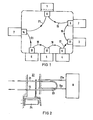
- FIG. 2 shows, for example, the interface control module 8 and the optical fibers 21 and 15 which lead into and out of the interface control module 8.
- an optical switch 22 is provided for the interface control module 8, through which the light flow selectively from the optical fiber 21 to the input 21a of the interface control module 8 and from the output 15a to the optical fiber 15, that is, via the interfaces Control module 8 or an optical fiber 23 lying parallel to it and bridging the interface control module 8 can be guided. Switching takes place by moving the ends of the optical fibers 15 and 21 with the aid of a relay 24. In the position shown, the interface control module 8 is bridged. This is e.g. B. makes sense if there is interference in the belonging Gen system component 1, such as a power failure. In this case, the flow of information is not interrupted. In the case of trouble-free operation, the relay 24 is energized and the light flux goes from the optical fiber 21 to the input 21a and via the interface control module 8 to its output 15a and from there to the optical fiber 15.
- optical switches can also be provided for the other interface control modules 9 to 14.
Landscapes
- Engineering & Computer Science (AREA)
- Computing Systems (AREA)
- Physics & Mathematics (AREA)
- Electromagnetism (AREA)
- Computer Networks & Wireless Communication (AREA)
- Signal Processing (AREA)
- Apparatus For Radiation Diagnosis (AREA)
- Optical Communication System (AREA)
Abstract
Die Erfindung betrifft eine Röntgendiagnostikanlage mit einer Mehrzahl von Anlagenkomponenten (1 bis 7). Jeder Anlagenkomponente (1 bis 7) ist je ein Schnittstellen-Steuerbaustein (8 bis 14) mit einem Datenein- und einem Datenausgang zugeordnet. Alle Schnittstellen-Steuerebausteine (8 bis 14) sind durch Lichtwellenleiter (15 bis 21) über ihre Datenein- und Datenausgänge zu einem Ring zusammengeschaltet. Es ist ein optischer Umschalter für die Schnittstellen-Steuerebausteine (8 bis 14) vorgesehen, durch den der Lichtfluß wahlweise über den jeweiligen Schnittstel- len-Steuerbaustein (8 bis 14) oder einen parallel dazu liegenden, den Schnittstellen-Steuerebaustein (8 bis 14) überbrückenden Lichtwellenleiter (23) führbar ist.
Description
Die Erfindung betrifft eine Röntgendiagnostikanlage mit einer Mehrzahl von Anlagenkomponenten sowie einer Leitung zur Informationsübertragung zwischen den einzelnen Anlagenkomponenten.The invention relates to an X-ray diagnostic system with a plurality of system components and a line for information transmission between the individual system components.
In der modernen Röntgentechnik wird häufig eine Vielzahl von Anlagenkomponenten, z.B. verschiedene Röntgengeräte und ein Röntgengenerator, zusammengeschaltet. Für die Ansteuerung der einzelnen Anlagenkomponenten ist dabei die Übertragung entsprechender Informationen erforderlich. Hierzu kann eine feste Verdrahtung, d.h. es können festgeschaltete Signalwege,vorgesehen sein. Bei einer derartigen Zusammenschaltung ist jedoch eine Verdrahtungsänderung für eine Änderung der Konfiguration erforderlich. Zur Verbesserung können die Anlagenkomponenten über eine Schleifenleitung zusammengeschaltet sein. Bei Verwendung eines Lichtwellenleiters zum Aufbau eines solchen Ringes ist jedoch sicherzustellen, daß beim Ausfall einer Anlagenkomponente die übrigen Anlagenkomponenten störungsfrei weiterarbeiten.A large number of system components, e.g. different X-ray machines and an X-ray generator, interconnected. In order to control the individual system components, the corresponding information must be transmitted. Fixed wiring, i.e. dedicated signal paths can be provided. With such an interconnection, however, a wiring change is required to change the configuration. To improve the system components can be interconnected via a loop line. When using an optical waveguide to set up such a ring, however, it must be ensured that if one system component fails, the other system components continue to operate without problems.
Der Erfindung liegt die Aufgabe zugrunde, eine Röntgendiagnostikanlage der eingangs genannten Art so auszubilden, daß eine besonders einfache Änderung der jeweiligen Konfiguration möglich ist und dabei bei Störungen in einer Anlagenkomponente die anderen Anlagenkomponenten nicht beeinflußt werden.The invention has for its object to design an X-ray diagnostic system of the type mentioned in such a way that a particularly simple change of the respective configuration is possible and the other system components are not influenced in the event of faults in one system component.
Diese Aufgabe ist erfindungsgemäß dadurch gelöst, daß jeder Anlagenkomponente je ein Schnittstellen-Steuerbaustein mit einem Datenein- und einem Datenausgang zugeordnet ist, daß alle Schnittstellen-Steuerbausteine durch Lichtwellenleiter über ihre Datenein- und Datenausgänge zu einem Ring zusammengeschaltet sind und daß ein optischer Umschalter für die Schnittstellen-Steuerbausteine vorhanden ist, durch den der Lichtfluß wahlweise über den jeweiligen Schnittstellen-Steuerbaustein oder einen parallel dazu liegenden, den Schnittstellen-Steuerbaustein überbrückenden Lichtwellenleiter führbar ist .Bei der erfindungsgemäßen Röntgendiagnostikanlage erfolgt die Informationsübertragung über Lichtwellenleiter. Für den logischen Datentransport, die Datensicherung, die dezentrale Kommunikationssteuerung, die Konfigurationsverwaltung und die Netzüberwachung ist der Schnittstellen-Steuerbaustein als Benutzerschnittstelle vorgesehen. Innerhalb des durch die Anzahl der Anlagenkomponenten vorgegebenen Rahmens sind beliebige räumliche und logische Konfigurationen möglich. Bei Störungen in einer Anlagenkomponente wird der zugeordnete Schnittstellen-Steuerbaustein über den optischen Umschalter überbrückt, so daß der Informationsfluß unter Umgehung der defekten Anlagenkomponente weitergehen kann.This object is achieved in that Each system component is assigned an interface control module with a data input and a data output, that all interface control modules are interconnected to form a ring by optical fibers via their data inputs and data outputs, and that there is an optical switch for the interface control modules the light flow can be guided either via the respective interface control module or an optical fiber lying parallel to it, bridging the interface control module. In the X-ray diagnostic system according to the invention, the information is transmitted via optical fibers. The interface control module is provided as a user interface for logical data transport, data backup, decentralized communication control, configuration management and network monitoring. Any spatial and logical configurations are possible within the framework specified by the number of system components. In the event of faults in a system component, the assigned interface control module is bridged using the optical switch, so that the flow of information can continue, bypassing the defective system component.
Die Erfindung ist nachfolgend anhand eines in der Zeichnung dargestellten Ausführungsbeispieles näher erläutert. Es zeigen:
- Fig. 1 eine Röntgendiagnostikanlage nach der Erfindung, und
- Fig. 2 eine Einzelheit der Röntgendiagnostikanlage gemäß
Figur 1.
- Fig. 1 is an X-ray diagnostic system according to the invention, and
- 2 shows a detail of the X-ray diagnostic system according to FIG. 1.
In der Figur 1 ist eine Röntgendiagnostikanlage mit einer Mehrzahl von Anlagenkomponenten 1 bis 7 dargestellt. Die Anlagenkomponente 1 kann beispielsweise ein Röntgengenerator und die Anlagenkomponenten 2 bis 7 können beispielsweise Röntgendiagnostikgeräte sein.An X-ray diagnostic system is shown in FIG a plurality of
Jeder Anlagenkomponente 1 bis 7 ist je ein Schnittstellen-Steuerbaustein 8 bis 14 zugeordnet. Jeder Schnittstellen-Steuerbaustein hat je einen Datenein- und einen Datenausgang. Alle Schnittstellen-Steuerbausteine sind durch Lichtwellenleiter 15 bis 21 für die Informationsübertragung über ihre Datenein- und Datenausgänge zu einem Ring zusammengeschaltet. Dadurch erfolgen ein logischer Datentransport, die Datensicherung, eine dezentrale Kommunikationssteuerung, die Konfigurationsverwaltung und die Netzüberwachung. Die Schnittstellen-Steuerbausteine 8 bis 14 ergeben Benutzerschnittstellen. Durch Programmänderung ist dabei eine einfache Änderung der Konfiguration möglich.An
Die Figur 2 zeigt beispielsweise den Schnittstellen-Steuerbaustein 8 sowie die Lichtwellenleiter 21 und 15, die in den Schnittstellen-Steuerbaustein 8 hinein- bzw. aus ihm herausführen. Aus der Figur 2 geht hervor, daß für den Schnittstellen-Steuerbaustein 8 ein optitischer Umschalter 22 vorgesehen ist, durch den der Lichtfluß wahlweise vom Lichtwellenleiter 21 auf den Eingang 21a des Schnittstellen-Steuerbausteines 8 und vom Ausgang 15a zum Lichtwellenleiter 15, also über den Schnittstellen-Steuerbaustein 8 oder einen parallel dazu liegenden, den Schnittstellen-Steuerbaustein 8 überbrückenden Lichtwellenleiter 23 führbar ist. Die Umschaltung erfolgt durch Bewegung der Enden der Lichtwellenleiter 15 und 21 mit Hilfe eines Relais 24. In der gezeichneten Stellung ist der Schnittstellen-Steuerbaustein 8 überbrückt. Dies ist z. B. dann sinnvoll, wenn Störungen in der zugehörigen Anlagenkomponente 1, z.B. ein Stromausfall, vorliegen. In diesem Fall erfolgt keine Unterbrechung des Informationsflusses. Bei störungsfreiem Betrieb ist das Relais 24 erregt und der Lichtfluß geht vom Lichtwellenleiter 21 zum Eingang 21a und über den Schnittstellen-Steuerbaustein 8 zu dessen Ausgang 15a und von dort zum Lichtwellenleiter 15.FIG. 2 shows, for example, the
In gleicher Weise wie für den Schnittstellen-Steuerbaustein 8 können auch für die übrigen Schnittstellen-Steuerbausteine 9 bis 14 optische Umschalter vorgesehen sein.In the same way as for the
Claims (2)
Applications Claiming Priority (2)
| Application Number | Priority Date | Filing Date | Title |
|---|---|---|---|
| DE3336237 | 1983-10-05 | ||
| DE19833336237 DE3336237A1 (en) | 1983-10-05 | 1983-10-05 | X-RAY DIAGNOSTIC SYSTEM WITH A NUMBER OF SYSTEM COMPONENTS |
Publications (3)
| Publication Number | Publication Date |
|---|---|
| EP0136645A2 true EP0136645A2 (en) | 1985-04-10 |
| EP0136645A3 EP0136645A3 (en) | 1985-05-22 |
| EP0136645B1 EP0136645B1 (en) | 1988-06-22 |
Family
ID=6211076
Family Applications (1)
| Application Number | Title | Priority Date | Filing Date |
|---|---|---|---|
| EP84111372A Expired EP0136645B1 (en) | 1983-10-05 | 1984-09-24 | X-ray diagnostic arrangement with several radiological systems |
Country Status (2)
| Country | Link |
|---|---|
| EP (1) | EP0136645B1 (en) |
| DE (2) | DE3336237A1 (en) |
Cited By (5)
| Publication number | Priority date | Publication date | Assignee | Title |
|---|---|---|---|---|
| EP0245153A1 (en) * | 1986-05-06 | 1987-11-11 | General Electric Cgr S.A. | X-ray system with several ring-connected devices and a short-circuiting arrangement for each device |
| EP0245160A1 (en) * | 1986-05-06 | 1987-11-11 | General Electric Cgr S.A. | X-ray installation with a communication network |
| GB2280279A (en) * | 1993-07-22 | 1995-01-25 | Northern Telecom Ltd | Optically switched branching unit for submarine telecommunications systems |
| WO1998011722A1 (en) * | 1996-09-10 | 1998-03-19 | Miroshnichenko Sergei Ivanovic | High-definition television system |
| EP1146670A3 (en) * | 2000-04-15 | 2004-03-10 | Bayerische Motoren Werke Aktiengesellschaft | Coupling element for connecting an electrical equipment to an optical data bus |
Family Cites Families (7)
| Publication number | Priority date | Publication date | Assignee | Title |
|---|---|---|---|---|
| GB1534786A (en) * | 1976-06-29 | 1978-12-06 | Standard Telephones Cables Ltd | Data transmission system |
| DE2724841A1 (en) * | 1977-06-02 | 1978-12-14 | Philips Patentverwaltung | Switching control for X=ray generator - has modules linked over data and address buses from central control store |
| US4148558A (en) * | 1977-10-17 | 1979-04-10 | Ncr Corporation | Optical transmission line by-pass relay |
| DE2827064A1 (en) * | 1978-06-20 | 1980-01-03 | Siemens Ag | METHOD FOR CONTROLLING SEVERAL X-RAY DEVICES IN A ROOM |
| US4234969A (en) * | 1978-09-05 | 1980-11-18 | Ncr Corporation | Bidirectional optical coupler for a data processing system |
| DE2850683A1 (en) * | 1978-11-22 | 1980-06-04 | Siemens Ag | X=ray diagnostic system using microprocessor controlling functions - has data transfer via interface with 8-bit control bug and 8-bit data bus |
| DE3036217C2 (en) * | 1980-09-25 | 1986-12-18 | Siemens AG, 1000 Berlin und 8000 München | Remote-controlled medical device |
-
1983
- 1983-10-05 DE DE19833336237 patent/DE3336237A1/en not_active Withdrawn
-
1984
- 1984-09-24 DE DE8484111372T patent/DE3472353D1/en not_active Expired
- 1984-09-24 EP EP84111372A patent/EP0136645B1/en not_active Expired
Cited By (9)
| Publication number | Priority date | Publication date | Assignee | Title |
|---|---|---|---|---|
| EP0245153A1 (en) * | 1986-05-06 | 1987-11-11 | General Electric Cgr S.A. | X-ray system with several ring-connected devices and a short-circuiting arrangement for each device |
| EP0245160A1 (en) * | 1986-05-06 | 1987-11-11 | General Electric Cgr S.A. | X-ray installation with a communication network |
| FR2598583A1 (en) * | 1986-05-06 | 1987-11-13 | Thomson Cgr | RADIOLOGY INSTALLATION WITH COMMUNICATION NETWORK |
| FR2598582A1 (en) * | 1986-05-06 | 1987-11-13 | Thomson Cgr | RADIOLOGY INSTALLATION WITH MULTIPLE CONTROL DEVICES ACCORDING TO A LOOP WITH A SHORT-CIRCUIT DEVICE FOR EACH APPARATUS |
| US5054044A (en) * | 1986-05-06 | 1991-10-01 | Thomson-Cgr | Radiology installation with a communications network |
| GB2280279A (en) * | 1993-07-22 | 1995-01-25 | Northern Telecom Ltd | Optically switched branching unit for submarine telecommunications systems |
| GB2280279B (en) * | 1993-07-22 | 1996-06-26 | Northern Telecom Ltd | Branching unit for submarine telecommunications systems |
| WO1998011722A1 (en) * | 1996-09-10 | 1998-03-19 | Miroshnichenko Sergei Ivanovic | High-definition television system |
| EP1146670A3 (en) * | 2000-04-15 | 2004-03-10 | Bayerische Motoren Werke Aktiengesellschaft | Coupling element for connecting an electrical equipment to an optical data bus |
Also Published As
| Publication number | Publication date |
|---|---|
| DE3336237A1 (en) | 1985-04-18 |
| EP0136645A3 (en) | 1985-05-22 |
| EP0136645B1 (en) | 1988-06-22 |
| DE3472353D1 (en) | 1988-07-28 |
Similar Documents
| Publication | Publication Date | Title |
|---|---|---|
| WO1999005811A1 (en) | Method and device for transmitting data by wavelength division multiplexing in an optical ring network | |
| EP0271169A2 (en) | Method and circuit arrangement for a decentralised replacement network | |
| DE3427891A1 (en) | ARRANGEMENT FOR TRANSFER OF INFORMATION WITH RECONFIGURATION | |
| DE19681134B4 (en) | communication system | |
| EP0279831B1 (en) | Device for the fail-safe transmission, in a reliable manner as regards signalling techniques, of serial data between fail-safe computers operating preferably on two channels by means of a twin-loop bus system | |
| EP0136645B1 (en) | X-ray diagnostic arrangement with several radiological systems | |
| DE2647738C2 (en) | Fault location method for loop-shaped communication systems and arrangement for carrying out this method | |
| DE3033071A1 (en) | PROCESS CALCULATOR | |
| DE3223779C2 (en) | ||
| DE4306032A1 (en) | Circuit arrangement for electro-optical changeover to standby during operation in communications systems | |
| AT398501B (en) | DEVICE FOR SIGNAL-SAFE OPERATION OF SEVERAL ELECTRICAL CONSUMERS | |
| EP0103151A2 (en) | Method of operating an electric-energy distribution installation | |
| EP1037408A2 (en) | Remotely configurable optical communication network | |
| DE2909512B1 (en) | Track interlocking | |
| DE3347610C2 (en) | ||
| EP1751896B1 (en) | Circuit for transmitting signals in a network node, particularly for a channel card for an optical wavelength division multiplex (wdm) signal transmitting device | |
| DE3529056C2 (en) | ||
| EP0719060B1 (en) | Control system for telecommunication installations | |
| EP1374358B1 (en) | Device for the temporary wiring, especially emergency wiring, of communication networks | |
| DE3207397C2 (en) | Method for monitoring the functionality of a digital transmission link | |
| DE3235661A1 (en) | Centrally controlled change-over device | |
| DE19513316A1 (en) | Ethernet-bus system with redundant bus interconnection of single port stations and segmented structuring | |
| EP0522193B1 (en) | Digital coupling network | |
| DE19747214A1 (en) | Telecommunication system with numerous interface ports | |
| DE3347609A1 (en) | Communication and monitoring system for traffic engineering |
Legal Events
| Date | Code | Title | Description |
|---|---|---|---|
| PUAI | Public reference made under article 153(3) epc to a published international application that has entered the european phase |
Free format text: ORIGINAL CODE: 0009012 |
|
| PUAL | Search report despatched |
Free format text: ORIGINAL CODE: 0009013 |
|
| AK | Designated contracting states |
Designated state(s): DE FR |
|
| AK | Designated contracting states |
Designated state(s): DE FR |
|
| RTI1 | Title (correction) | ||
| 17P | Request for examination filed |
Effective date: 19850627 |
|
| 17Q | First examination report despatched |
Effective date: 19861104 |
|
| GRAA | (expected) grant |
Free format text: ORIGINAL CODE: 0009210 |
|
| AK | Designated contracting states |
Kind code of ref document: B1 Designated state(s): DE FR |
|
| REF | Corresponds to: |
Ref document number: 3472353 Country of ref document: DE Date of ref document: 19880728 |
|
| ET | Fr: translation filed | ||
| PLBE | No opposition filed within time limit |
Free format text: ORIGINAL CODE: 0009261 |
|
| STAA | Information on the status of an ep patent application or granted ep patent |
Free format text: STATUS: NO OPPOSITION FILED WITHIN TIME LIMIT |
|
| 26N | No opposition filed | ||
| PGFP | Annual fee paid to national office [announced via postgrant information from national office to epo] |
Ref country code: DE Payment date: 19891127 Year of fee payment: 6 |
|
| PGFP | Annual fee paid to national office [announced via postgrant information from national office to epo] |
Ref country code: FR Payment date: 19900925 Year of fee payment: 7 |
|
| PG25 | Lapsed in a contracting state [announced via postgrant information from national office to epo] |
Ref country code: DE Effective date: 19910601 |
|
| PG25 | Lapsed in a contracting state [announced via postgrant information from national office to epo] |
Ref country code: FR Effective date: 19920529 |
|
| REG | Reference to a national code |
Ref country code: FR Ref legal event code: ST |