EP0136657B1 - Table extensible - Google Patents
Table extensible Download PDFInfo
- Publication number
- EP0136657B1 EP0136657B1 EP84111500A EP84111500A EP0136657B1 EP 0136657 B1 EP0136657 B1 EP 0136657B1 EP 84111500 A EP84111500 A EP 84111500A EP 84111500 A EP84111500 A EP 84111500A EP 0136657 B1 EP0136657 B1 EP 0136657B1
- Authority
- EP
- European Patent Office
- Prior art keywords
- table top
- elements
- pairs
- accordance
- cooperating
- Prior art date
- Legal status (The legal status is an assumption and is not a legal conclusion. Google has not performed a legal analysis and makes no representation as to the accuracy of the status listed.)
- Expired
Links
- NJPPVKZQTLUDBO-UHFFFAOYSA-N novaluron Chemical compound C1=C(Cl)C(OC(F)(F)C(OC(F)(F)F)F)=CC=C1NC(=O)NC(=O)C1=C(F)C=CC=C1F NJPPVKZQTLUDBO-UHFFFAOYSA-N 0.000 claims description 17
- 238000005452 bending Methods 0.000 claims description 8
- 239000000463 material Substances 0.000 description 4
- 238000010276 construction Methods 0.000 description 3
- 239000011093 chipboard Substances 0.000 description 1
- 229910003460 diamond Inorganic materials 0.000 description 1
- 239000010432 diamond Substances 0.000 description 1
- 238000006073 displacement reaction Methods 0.000 description 1
- 238000003197 gene knockdown Methods 0.000 description 1
- 230000001788 irregular Effects 0.000 description 1
- 230000013011 mating Effects 0.000 description 1
- 230000002787 reinforcement Effects 0.000 description 1
- 238000007665 sagging Methods 0.000 description 1
Images

Classifications
-
- E—FIXED CONSTRUCTIONS
- E01—CONSTRUCTION OF ROADS, RAILWAYS, OR BRIDGES
- E01D—CONSTRUCTION OF BRIDGES, ELEVATED ROADWAYS OR VIADUCTS; ASSEMBLY OF BRIDGES
- E01D15/00—Movable or portable bridges; Floating bridges
- E01D15/12—Portable or sectional bridges
- E01D15/133—Portable or sectional bridges built-up from readily separable standardised sections or elements, e.g. Bailey bridges
-
- A—HUMAN NECESSITIES
- A47—FURNITURE; DOMESTIC ARTICLES OR APPLIANCES; COFFEE MILLS; SPICE MILLS; SUCTION CLEANERS IN GENERAL
- A47B—TABLES; DESKS; OFFICE FURNITURE; CABINETS; DRAWERS; GENERAL DETAILS OF FURNITURE
- A47B1/00—Extensible tables
- A47B1/08—Extensible tables with extensible frames or with additional legs
-
- A—HUMAN NECESSITIES
- A47—FURNITURE; DOMESTIC ARTICLES OR APPLIANCES; COFFEE MILLS; SPICE MILLS; SUCTION CLEANERS IN GENERAL
- A47B—TABLES; DESKS; OFFICE FURNITURE; CABINETS; DRAWERS; GENERAL DETAILS OF FURNITURE
- A47B2200/00—General construction of tables or desks
- A47B2200/0066—Workstations
- A47B2200/0079—Conference or video conference table
Definitions
- the present invention relates to a flat plate like structure such as a table or a bridge as set forth in the preamble of claim 1, e.g. to extendable tables which are extended by adding a number of leaves in between the two end parts of the table.
- a table is for example known from FR-A-2 188 422.
- the table top elements abut one another at straight abutment lines and four pairs of cooperating interfitting male and female members are spaced apart along each abutment line.
- No rails or supports other than the interfitting male and female members are provided for the table elements or leaves disposed between the end elements which are provided with pedestals.
- the present invention provides a table of the initially named kind which is characterised in that the or each said abutment line comprises a non-straight line and in that said at least three pairs of cooperating male and female members are disposed in a non-collinear arrangement along the or each said abutment lines, whereby the weight of an element such as a table top element not provided with a pedestal is carried by shear stresses in the cooperating members and by bending stresses in the table top element itself.
- a table constructed in this way makes it possible to support extension leaves, added either in the middle of the table or to one or both ends thereof, in such a way that sagging is avoided without the need for substantial intermediate supports or support rails extending over the full length of the table.
- the above arrangement makes it possible for the weight of the non supported table top elements or leaves to be carried by shear stresses in the pairs of cooperating interfitting male and female members and by bending stresses in the table top element itself.
- substantial shear stresses can be born in practice by relatively slender members, and as most table top elements are themselves generally very resistant to bending, the arrangement of the invention makes it possible to support substantial weights stably without the need for massive supports and reinforcements.
- the abutment lines can follow a wavy line, roughly of S-shape, or zig-zag shape or any other regular or irregular non-straight line.
- the abutment lines are S-shaped or V-shaped in plan view which makes it possible to provide a substantial distance or offset between a line joining the two outermost of the three pairs of cooperating male and female members and the third intermediate pair.
- S-shaped and V-shaped lines provide a pleasing external appearence for the table.
- V-shaped abutment lines it is possible to provide a center leaf which is approximately of diamond shape. Further extension leaves can be of chevron shape.
- first and second table top elements located at first and second ends of the table are provided with pedestals, and at least one intermediate table top element is provided between said first and second table top elements.
- the intermediate table top element conveniently forms an extension leaf which can be added or removed at will to shorten or increase the length of the table.
- the cooperating male and female members serve to prevent relative movement of adjacent table top elements in the direction normal to their plane, and also in the direction across the table and to this extent execute a function similar to the dowels normally provided for locating extension leaves in extendable tables.
- the male and female members can be provided at the abutting edges of the table top elements so that the leaves need be no thicker than the leaf material itself.
- the cooperating male and female members can be provided beneath the abutting edges of the table top elements. This arrangement may be preferred where the table top elements are formed of a material such as chipboard and where problems might arise in feeding the bending stresses into the table top element itself at the pairs of male and female members.
- the table top elements have undersides and are conveniently provided with a guide groove along the said undersides. This makes it possible to slide a first flat pedestal element into position beneath the table.
- a second pedestal element which can also be a flat, a real, plate can be slotted together with the first mentioned pedestal plate at right angles and forms a very stable cross shaped pedestal of pleasing design. Because both the table top elements and the pedestal elements are all flat plates they can readily be stored and are economical to transport.
- the present invention is not restricted to tables but can also be extended to other flat plate like structures such as a bridge formed of bridge plates.
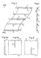
- the table top comprises two end parts or elements 1 with extension leaves or elements 2 disposed intermediate the two endparts.
- the two endparts or elements are supported by means of pedestals 3.
- the pedestals each extend under two basic elements of the table top, this is however not essential.
- an extension leaf 2 has two non-straight S-shaped abutment edges 5 which are provided with four pairs of mating joining means.
- Each said pair of joining means comprises interfitting male and female members, such as a pin 7 and a tube or socket member 8 provided to receive the pin 7.
- the pins 7 should be a good fit in the tubes 8.
- the pins 7, which point in the extendable direction of the table are located beneath the edge of the table top elements and the tubes 8 are correspondingly positioned below the associated table top element.
- the pins and sockets can be provided at or in the abutting side edges of the associated table top element. In any event each leaf must be provided with at least three pairs of male and female members, which are not to be on one straight line.
- the table is mounted by placing one leaf on a pedestal, and adding the next leaf by sliding the pins on one leaf into the tubes of the other leaf and so on. In this way as many extension leaves as required can be added.
- the pedestals consist of pairs of plates 10 and 11.
- a slot is cut halfway through each plate with the slots in the two plates extending in opposite directions to one another along the respective central vertical axes 12, 13 so that the plates may be slotted together to form a pedestal in the form of a cross when seen from above.
- a rail 15 along the upper edge of pedestal plate 10 (which is the plate with the slot along the upper half) is slidable in and along a guide groove 16 provided on the underside of the table top elements in the median line of the assembly.
- the guide groove 16 holds the rail 15 in the vertical direction in tongue in groove manner, and thus locks the other pedestal plate 11 in position. Cutouts 17 in pedestal plate 11 permit movement of the plate past the tubes 8.
- the present invention is specifically directed to a table it will be appreciated that the underlying principle for connecting generally flat plate-like elements could also be used in other fields, for example in the construction industry for the construction of bridges and buildings.
- the bridge plates of a bridge for example a temporary bridge, could be connected together in accordance with the present teaching with a substantial saving of material. This would be particularly advantageous for bridges for military purposes because it would only be necessary to transport a number of flat plates elements or structures to the bridge building site with substantial saving in the amount of space and number of transport vehicles required.
Landscapes
- Engineering & Computer Science (AREA)
- Architecture (AREA)
- Civil Engineering (AREA)
- Structural Engineering (AREA)
- Tables And Desks Characterized By Structural Shape (AREA)
Claims (9)
Applications Claiming Priority (2)
| Application Number | Priority Date | Filing Date | Title |
|---|---|---|---|
| IL69877 | 1983-09-30 | ||
| IL69877A IL69877A0 (en) | 1983-09-30 | 1983-09-30 | Extendable table |
Publications (3)
| Publication Number | Publication Date |
|---|---|
| EP0136657A2 EP0136657A2 (fr) | 1985-04-10 |
| EP0136657A3 EP0136657A3 (en) | 1986-12-30 |
| EP0136657B1 true EP0136657B1 (fr) | 1990-06-13 |
Family
ID=11054567
Family Applications (1)
| Application Number | Title | Priority Date | Filing Date |
|---|---|---|---|
| EP84111500A Expired EP0136657B1 (fr) | 1983-09-30 | 1984-09-26 | Table extensible |
Country Status (4)
| Country | Link |
|---|---|
| US (1) | US4878439A (fr) |
| EP (1) | EP0136657B1 (fr) |
| DE (1) | DE3482436D1 (fr) |
| IL (1) | IL69877A0 (fr) |
Cited By (1)
| Publication number | Priority date | Publication date | Assignee | Title |
|---|---|---|---|---|
| DE3538003A1 (de) * | 1985-10-25 | 1987-04-30 | Kurz Gmbh | Variabler tisch |
Families Citing this family (54)
| Publication number | Priority date | Publication date | Assignee | Title |
|---|---|---|---|---|
| DE9006189U1 (de) * | 1990-05-29 | 1990-08-02 | Nalbach Design GmbH, 1000 Berlin | Flächenschlußform für Tisch |
| USD417094S (en) | 1998-08-20 | 1999-11-30 | Hon Technology Inc. | Table |
| NO993308A (no) * | 1999-07-02 | 2000-02-14 | Herleiv Velde | Anordning ved bord og anvendelse av anordningen |
| US6363866B1 (en) | 2000-01-20 | 2002-04-02 | Hou Technology Inc. | Table construction |
| US6698363B2 (en) * | 2002-07-30 | 2004-03-02 | Outdoor Designs, Ltd. | Extendable table |
| USD486328S1 (en) | 2003-05-08 | 2004-02-10 | Thomasville Furniture Industries, Inc. | Table |
| USD486327S1 (en) | 2003-09-29 | 2004-02-10 | Amini Innovation Corp. | Double pedestal dining table |
| USD486014S1 (en) | 2003-09-29 | 2004-02-03 | Amini Innovation Corp. | Double pedestal dining table |
| RU2245668C1 (ru) * | 2004-03-12 | 2005-02-10 | Общество с ограниченной ответственностью "Проммебель" | Стол модульный |
| US7107914B2 (en) * | 2004-05-04 | 2006-09-19 | Sherman Brad J | Modular table system |
| USD544728S1 (en) | 2004-09-14 | 2007-06-19 | Jack Schmitt | Double pedestal table |
| US20060102056A1 (en) * | 2004-11-16 | 2006-05-18 | Wolfe Kevin M | Removable table extension |
| USD532222S1 (en) | 2005-03-17 | 2006-11-21 | Amini Innovation Corp. | Table |
| USD540069S1 (en) | 2005-03-29 | 2007-04-10 | Amini Innovation Corp. | Dining table |
| USD550483S1 (en) | 2005-03-29 | 2007-09-11 | Amini Innovation Corp. | Table |
| USD557042S1 (en) | 2005-03-29 | 2007-12-11 | Amini Innovation Corp. | Table |
| USD539058S1 (en) | 2005-03-29 | 2007-03-27 | Amini Innovation Corp. | Table |
| US20070277710A1 (en) * | 2006-06-06 | 2007-12-06 | Gray Daniel G | Modular conference table |
| USD569660S1 (en) | 2007-01-26 | 2008-05-27 | Amini Innovation Corporation | Table |
| USD575080S1 (en) | 2007-07-23 | 2008-08-19 | Amini Innovation Corporation | Table |
| USD592893S1 (en) | 2007-10-11 | 2009-05-26 | Amini Innovation Corporation | Table |
| USD597768S1 (en) | 2008-01-19 | 2009-08-11 | Amini Innovation Corporation | Table |
| USD586154S1 (en) | 2008-03-14 | 2009-02-10 | Amini Innovation Corp. | Table |
| USD626358S1 (en) | 2008-07-03 | 2010-11-02 | Amini Innovation Corporation | Table |
| USD610837S1 (en) | 2008-07-25 | 2010-03-02 | Amini Innovation Corporation | Table |
| USD594676S1 (en) | 2008-07-28 | 2009-06-23 | Amini Innovation Corporation | Table |
| USD605432S1 (en) | 2009-01-28 | 2009-12-08 | Amini Innovation Corporation | Table |
| USD639583S1 (en) | 2010-02-05 | 2011-06-14 | Amini Innovation Corporation | Table |
| US8161891B2 (en) | 2010-04-01 | 2012-04-24 | Blue Sky Innovation Group, Inc. | Expandable table |
| USD644856S1 (en) | 2010-07-23 | 2011-09-13 | Amini Innovation Corporation | Table |
| USD645277S1 (en) | 2010-08-13 | 2011-09-20 | Amini Innovation Corporation | Table |
| USD660617S1 (en) | 2011-08-18 | 2012-05-29 | Amini Innovation Corporation | Table |
| USD661128S1 (en) | 2011-08-18 | 2012-06-05 | Amini Innovation Corporation | Cocktail table |
| USD684413S1 (en) | 2012-07-16 | 2013-06-18 | Amini Innovation Corporation | Table |
| USD701716S1 (en) | 2012-11-16 | 2014-04-01 | Amini Innovation Corporation | Table |
| USD713185S1 (en) | 2013-02-22 | 2014-09-16 | Amini Innovation Corporation | Table |
| US9615663B2 (en) | 2013-03-16 | 2017-04-11 | Clark Evan Davis | Modular tool-less furniture |
| EP2829197B1 (fr) * | 2013-07-25 | 2016-10-26 | VS Vereinigte Spezialmöbelfabriken GmbH & Co. KG | Table et jeu de pièces détachées pour la création d'un agencement de mobilier |
| USD759410S1 (en) | 2014-06-16 | 2016-06-21 | Amini Innovation Corporation | Cocktail table |
| US10094402B2 (en) * | 2014-09-23 | 2018-10-09 | Marmo Arredo S.P.A. | Worktop for pieces of furniture and method for joining slabs so as to obtain said worktop |
| USD807088S1 (en) * | 2014-10-15 | 2018-01-09 | Anne Juge | Table base |
| US10227162B2 (en) | 2015-09-21 | 2019-03-12 | Clark Evan Davis | Stackable and collapsible crate |
| USD801737S1 (en) | 2016-03-28 | 2017-11-07 | Amini Innovation Corporation | Table |
| USD799868S1 (en) | 2016-05-04 | 2017-10-17 | Amini Innovation Corporation | Table |
| US10823214B2 (en) | 2016-10-26 | 2020-11-03 | Clark Evan Davis | Modular furniture with distributed pressure panel joint |
| USD863834S1 (en) * | 2017-06-08 | 2019-10-22 | Life Fitness, Llc | Meeting table |
| US10687617B2 (en) | 2017-08-01 | 2020-06-23 | Clark Davis | Modular shelf system with tab and slot mounting |
| US10415612B2 (en) | 2017-08-01 | 2019-09-17 | Clark Evan Davis | Modular furniture with stressed panel dovetail joint |
| US11346382B2 (en) | 2017-08-30 | 2022-05-31 | Clark Evan Davis | Modular furniture with stressed dovetail tab joint |
| US11154137B2 (en) | 2017-08-30 | 2021-10-26 | Clark Evan Davis | Modular furniture with locking tab and slot joint |
| US11085474B2 (en) | 2017-09-15 | 2021-08-10 | Clark Davis | Furniture with flexible dovetail dowel and slot joint |
| US11578739B2 (en) | 2017-10-05 | 2023-02-14 | Clark Davis | Furniture with interwoven tab and slot joint |
| US11083293B2 (en) | 2019-10-17 | 2021-08-10 | Clark Davis | Modular stackable shelves |
| US11767867B2 (en) | 2020-11-17 | 2023-09-26 | Clark Davis | Pivoting joint for wooden furniture |
Family Cites Families (12)
| Publication number | Priority date | Publication date | Assignee | Title |
|---|---|---|---|---|
| US1017062A (en) * | 1909-04-01 | 1912-02-13 | William L Pfefferkorn | Pedestal extension-table. |
| US1547685A (en) * | 1922-02-25 | 1925-07-28 | Rhodes Anita | Extension table |
| US2556362A (en) * | 1947-11-14 | 1951-06-12 | William S Crumpler | Knockdown portable table |
| FR1101580A (fr) * | 1954-06-03 | 1955-10-07 | Table dont le plateau peut être juxtaposé de façon jointive aux plateaux d'autres tables similaires pour former une table unique | |
| US2890087A (en) * | 1958-06-02 | 1959-06-09 | Myron B Stevens | Individually stable connected tables |
| US3053598A (en) * | 1960-08-08 | 1962-09-11 | Cheslow Ernest | Set of tables |
| FR2188422A6 (fr) * | 1972-03-30 | 1974-01-18 | Raoult Gustave | |
| US3826206A (en) * | 1972-10-12 | 1974-07-30 | Directional Ind Inc | Modular furniture or like articles and modular units therefor |
| US3915100A (en) * | 1973-02-05 | 1975-10-28 | Henry E Sullivan | Panel fastening device |
| IT1082918B (it) * | 1977-03-22 | 1985-05-21 | Pozzan Bruno | Tavolo ad elementi componibili,particolarmente per uso didattico |
| US4158335A (en) * | 1977-05-09 | 1979-06-19 | Patricia Belcastro | Apparatus to join table tops together |
| US4266882A (en) * | 1978-10-19 | 1981-05-12 | Wilhelmi Julius B | Table section aligning and fastening device |
-
1983
- 1983-09-30 IL IL69877A patent/IL69877A0/xx unknown
-
1984
- 1984-09-26 DE DE8484111500T patent/DE3482436D1/de not_active Expired - Lifetime
- 1984-09-26 EP EP84111500A patent/EP0136657B1/fr not_active Expired
- 1984-09-28 US US06/655,710 patent/US4878439A/en not_active Expired - Fee Related
Cited By (1)
| Publication number | Priority date | Publication date | Assignee | Title |
|---|---|---|---|---|
| DE3538003A1 (de) * | 1985-10-25 | 1987-04-30 | Kurz Gmbh | Variabler tisch |
Also Published As
| Publication number | Publication date |
|---|---|
| DE3482436D1 (de) | 1990-07-19 |
| US4878439A (en) | 1989-11-07 |
| EP0136657A2 (fr) | 1985-04-10 |
| IL69877A0 (en) | 1983-12-30 |
| EP0136657A3 (en) | 1986-12-30 |
Similar Documents
| Publication | Publication Date | Title |
|---|---|---|
| US4878439A (en) | Extendable table | |
| US6715427B2 (en) | Suspended storage structure | |
| US4732088A (en) | Set of modular elements for forming office furnitures | |
| US3722704A (en) | Structural components for the composition of disassemblable pieces offurniture | |
| US4821649A (en) | Sheet metal shelving | |
| US5813737A (en) | Construction system | |
| US20020178979A1 (en) | Slot-to-slot interlocking shelving | |
| IL30946A (en) | Foot structure for furniture | |
| US4127072A (en) | Modular shelf | |
| US2840200A (en) | Structural connector | |
| US4540308A (en) | Joint for furniture support structure | |
| CA2590998A1 (fr) | Table de conference modulaire | |
| US20060174407A1 (en) | Easy to assemble bed base, two-component connector & kit | |
| SE8502099L (sv) | Terassanleggning | |
| GB1600990A (en) | Sectional screens | |
| US4543759A (en) | Support structures | |
| US3909914A (en) | Method of forming a structure using jointing members | |
| US6216415B1 (en) | Element of load-bearing structures, especially girders for modular shelves | |
| EP0169697A1 (fr) | Système d'assemblage | |
| US4312454A (en) | Modular construction element for building a pigeonhole-type wall | |
| GB2630135A (en) | Temporary flooring systems | |
| GB2279867A (en) | Support structure, e.g. for a table - top or seat | |
| EP0139599A2 (fr) | Moyen de support d'un pivot sur poutres, sous-poutres etc. | |
| EP0477125A1 (fr) | Système d'étagères sous forme de boîtes | |
| EP0499938A1 (fr) | Structure réticulaire modulaire |
Legal Events
| Date | Code | Title | Description |
|---|---|---|---|
| PUAI | Public reference made under article 153(3) epc to a published international application that has entered the european phase |
Free format text: ORIGINAL CODE: 0009012 |
|
| AK | Designated contracting states |
Designated state(s): DE FR GB IT |
|
| PUAL | Search report despatched |
Free format text: ORIGINAL CODE: 0009013 |
|
| AK | Designated contracting states |
Kind code of ref document: A3 Designated state(s): DE FR GB IT |
|
| 17P | Request for examination filed |
Effective date: 19870630 |
|
| 17Q | First examination report despatched |
Effective date: 19880614 |
|
| GRAA | (expected) grant |
Free format text: ORIGINAL CODE: 0009210 |
|
| AK | Designated contracting states |
Kind code of ref document: B1 Designated state(s): DE FR GB IT |
|
| REF | Corresponds to: |
Ref document number: 3482436 Country of ref document: DE Date of ref document: 19900719 |
|
| ITF | It: translation for a ep patent filed | ||
| ET | Fr: translation filed | ||
| PLBE | No opposition filed within time limit |
Free format text: ORIGINAL CODE: 0009261 |
|
| STAA | Information on the status of an ep patent application or granted ep patent |
Free format text: STATUS: NO OPPOSITION FILED WITHIN TIME LIMIT |
|
| 26N | No opposition filed | ||
| ITTA | It: last paid annual fee | ||
| PGFP | Annual fee paid to national office [announced via postgrant information from national office to epo] |
Ref country code: FR Payment date: 19921015 Year of fee payment: 9 |
|
| PGFP | Annual fee paid to national office [announced via postgrant information from national office to epo] |
Ref country code: GB Payment date: 19921109 Year of fee payment: 9 |
|
| PGFP | Annual fee paid to national office [announced via postgrant information from national office to epo] |
Ref country code: DE Payment date: 19921111 Year of fee payment: 9 |
|
| PG25 | Lapsed in a contracting state [announced via postgrant information from national office to epo] |
Ref country code: GB Effective date: 19930926 |
|
| GBPC | Gb: european patent ceased through non-payment of renewal fee |
Effective date: 19930926 |
|
| PG25 | Lapsed in a contracting state [announced via postgrant information from national office to epo] |
Ref country code: FR Free format text: LAPSE BECAUSE OF NON-PAYMENT OF DUE FEES Effective date: 19940531 |
|
| PG25 | Lapsed in a contracting state [announced via postgrant information from national office to epo] |
Ref country code: DE Effective date: 19940601 |
|
| REG | Reference to a national code |
Ref country code: FR Ref legal event code: ST |