EP0136664A2 - Dispositif de mise en contact pour analyseur de gaz - Google Patents
Dispositif de mise en contact pour analyseur de gaz Download PDFInfo
- Publication number
- EP0136664A2 EP0136664A2 EP84111569A EP84111569A EP0136664A2 EP 0136664 A2 EP0136664 A2 EP 0136664A2 EP 84111569 A EP84111569 A EP 84111569A EP 84111569 A EP84111569 A EP 84111569A EP 0136664 A2 EP0136664 A2 EP 0136664A2
- Authority
- EP
- European Patent Office
- Prior art keywords
- gas
- carrier gas
- contact tube
- sample water
- bore
- Prior art date
- Legal status (The legal status is an assumption and is not a legal conclusion. Google has not performed a legal analysis and makes no representation as to the accuracy of the status listed.)
- Granted
Links
- XLYOFNOQVPJJNP-UHFFFAOYSA-N water Substances O XLYOFNOQVPJJNP-UHFFFAOYSA-N 0.000 claims abstract description 35
- 239000012159 carrier gas Substances 0.000 claims abstract description 24
- 239000007789 gas Substances 0.000 claims abstract description 20
- 238000000926 separation method Methods 0.000 claims abstract description 8
- 238000005259 measurement Methods 0.000 claims abstract description 4
- 238000010438 heat treatment Methods 0.000 claims description 3
- 239000000203 mixture Substances 0.000 abstract description 2
- 238000000357 thermal conductivity detection Methods 0.000 abstract description 2
- XKRFYHLGVUSROY-UHFFFAOYSA-N Argon Chemical compound [Ar] XKRFYHLGVUSROY-UHFFFAOYSA-N 0.000 description 4
- IJGRMHOSHXDMSA-UHFFFAOYSA-N Atomic nitrogen Chemical compound N#N IJGRMHOSHXDMSA-UHFFFAOYSA-N 0.000 description 2
- 229910052786 argon Inorganic materials 0.000 description 2
- QVGXLLKOCUKJST-UHFFFAOYSA-N atomic oxygen Chemical compound [O] QVGXLLKOCUKJST-UHFFFAOYSA-N 0.000 description 2
- 238000003754 machining Methods 0.000 description 2
- 239000001301 oxygen Substances 0.000 description 2
- 229910052760 oxygen Inorganic materials 0.000 description 2
- 230000015572 biosynthetic process Effects 0.000 description 1
- 230000003197 catalytic effect Effects 0.000 description 1
- 239000003638 chemical reducing agent Substances 0.000 description 1
- 238000013461 design Methods 0.000 description 1
- 238000001514 detection method Methods 0.000 description 1
- 238000005485 electric heating Methods 0.000 description 1
- 239000001257 hydrogen Substances 0.000 description 1
- 229910052739 hydrogen Inorganic materials 0.000 description 1
- 125000004435 hydrogen atom Chemical class [H]* 0.000 description 1
- 239000007788 liquid Substances 0.000 description 1
- 238000004519 manufacturing process Methods 0.000 description 1
- 238000000034 method Methods 0.000 description 1
- 239000002808 molecular sieve Substances 0.000 description 1
- 238000012544 monitoring process Methods 0.000 description 1
- 229910052757 nitrogen Inorganic materials 0.000 description 1
- 230000001105 regulatory effect Effects 0.000 description 1
- 230000035945 sensitivity Effects 0.000 description 1
- URGAHOPLAPQHLN-UHFFFAOYSA-N sodium aluminosilicate Chemical compound [Na+].[Al+3].[O-][Si]([O-])=O.[O-][Si]([O-])=O URGAHOPLAPQHLN-UHFFFAOYSA-N 0.000 description 1
- 238000005476 soldering Methods 0.000 description 1
- 238000012360 testing method Methods 0.000 description 1
- 230000007704 transition Effects 0.000 description 1
- 238000003466 welding Methods 0.000 description 1
Images

Classifications
-
- G—PHYSICS
- G01—MEASURING; TESTING
- G01N—INVESTIGATING OR ANALYSING MATERIALS BY DETERMINING THEIR CHEMICAL OR PHYSICAL PROPERTIES
- G01N33/00—Investigating or analysing materials by specific methods not covered by groups G01N1/00 - G01N31/00
- G01N33/18—Water
-
- G—PHYSICS
- G01—MEASURING; TESTING
- G01N—INVESTIGATING OR ANALYSING MATERIALS BY DETERMINING THEIR CHEMICAL OR PHYSICAL PROPERTIES
- G01N1/00—Sampling; Preparing specimens for investigation
- G01N1/02—Devices for withdrawing samples
- G01N1/22—Devices for withdrawing samples in the gaseous state
Definitions
- the present invention relates to a contact apparatus for a gas analyzer for the quasi-continuous measurement of small gas fractions in a continuous water flow.
- a thermal conductivity detector and argon as the carrier gas, there is a detection limit of 0.01 ppb for hydrogen, 0.5 ppb for oxygen and 1 ppb for nitrogen.
- Typical measured values at power plants are between 1 and a few 100 ppb, while monitoring a process for catalytic oxygen removal also results in percentages.
- the continuously flowing sample water is brought into contact with a carrier gas under precisely defined conditions, the carrier gas, e.g. high-purity argon, which entrains the gases present in the sample water.
- the carrier gas e.g. high-purity argon
- the enriched gas mixture is chromatographically separated with a separating column filled with a molecular sieve and then detected quantitatively by means of thermal conductivity detection.
- the present invention relates to the contact apparatus in which the carrier gas is brought into contact with the sample water.
- a device of this type has already been described in German Offenlegungsschrift 23 63 370.7.
- the object of the present invention is the sensitivity and the measuring accuracy of the known device to increase.
- a largely constant temperature of sample water and carrier gas is important and the merging and separation of P robes water and carrier gas is to be made very carefully and under constant conditions.
- gas bubbles are to be avoided, which can lead to pressure fluctuations and thus to flow changes and could transport the moisture into the subsequent separation column.
- a contact apparatus according to the first claim is first proposed.
- the cylinder arranged inside the two coils with its openings at the upper and lower end and with the heating element contained therein results in a constant circulation of the water in the container due to convection, which is heated within the cylinder and rises accordingly and flows downwards outside the cylinder.
- the proposed arrangement of the heating element within the cylinder prevents individual hot strands from touching the contact tube directly and causing different temperatures there and in time.
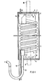
- Figures 1 to 4 show a possible embodiment of the invention.
- the container 1 consisting of a cylindrical part 2, a lid 3 and a bottom 4, contains two helically arranged tubes, namely the contact tube 5 and of substantially smaller diameter, the water supply tube 6, both of which are spaced around an inner one Cylinder 7 are wound, which abuts the bottom 4 and cover 3 and there each have a plurality of radial openings 8 distributed uniformly over the circumference.
- an electric heating element 9 is inserted centrally and tightly, which is regulated by a temperature measuring device 10, which is inserted tightly and centrally in the cover 3.
- the lower end of the contact tube 5 is welded into a separator block 11, which also carries a gas supply line 12 and a water drain line 13, which ends with a U-bend.
- the upper end of the water supply line 6, like the contact tube 5, is welded into a separating block 14 which also carries a gas discharge line 15 which leads upwards out of the container 1.
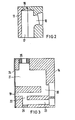
- FIG. 2 shows the lower separating block 11 from FIG. 1, with which the sample water emerging from the contact tube 5 is conducted to a drain and with which the carrier gas is introduced into the contact tube. It is important at this separation block that the carrier gas enters above the sample water, so that no gas bubbles can arise in the water flow. Furthermore, the transition between the bore 16 and the bore 17 should be rounded so that the sample water can flow there in a laminar manner and without the formation of drops. So that this rounding can be machined and checked, the separating block 11 is expediently separated into two parts before machining in accordance with the black line in bore 17 and only after the machining.
- Fig. 3 shows the separation block 14 in longitudinal section.
- the bores described in claim 4 are first made and then, as shown in FIG. 3, closed by welding or soldering a plate 24.
- the incoming sample water without carrier gas is passed through the holes 23 and 22 to the hole 19, which it on lower end into the contact tube 5 connected to the bore 20.
- This arrangement prevents 14 gas bubbles from forming within the separating block, which could lead to small pressure fluctuations or to a transport of moisture into the subsequent separating column.
- a gas collecting space 21 is arranged above the bores 19 and 20 and is also intended to prevent the transport of moisture with the carrier gas stream.
- a reducer 25 for the connection of the gas discharge line 15 is arranged.
- the bore 22 in the separating block 14 is closed by a plug 26.
- Fig. 4 shows an alternative to the U-bend of the water drainage line shown in Fig. 1.
- 13 also a gas-tight water drain 27, which can also be connected to the lower end of a separating block 11 according to FIG. 2.
- Both the U-bend and the water drain 27 should end in a space of atmospheric pressure so that the pressure in the contact tube 5 remains constant, and should also protect the contact tube against the entry of undesirable amounts of gas.
- the drain 27 consists of several welded pipe sockets and turned parts, the design of which can be seen in FIG. 4.
Landscapes
- Life Sciences & Earth Sciences (AREA)
- Health & Medical Sciences (AREA)
- Chemical & Material Sciences (AREA)
- Pathology (AREA)
- General Physics & Mathematics (AREA)
- Physics & Mathematics (AREA)
- Engineering & Computer Science (AREA)
- Analytical Chemistry (AREA)
- Biochemistry (AREA)
- General Health & Medical Sciences (AREA)
- Immunology (AREA)
- Molecular Biology (AREA)
- Biomedical Technology (AREA)
- Food Science & Technology (AREA)
- Medicinal Chemistry (AREA)
- Sampling And Sample Adjustment (AREA)
- Investigating Or Analyzing Non-Biological Materials By The Use Of Chemical Means (AREA)
Priority Applications (1)
| Application Number | Priority Date | Filing Date | Title |
|---|---|---|---|
| AT84111569T ATE49299T1 (de) | 1983-10-06 | 1984-09-27 | Kontaktapparat fuer gasanalysator. |
Applications Claiming Priority (2)
| Application Number | Priority Date | Filing Date | Title |
|---|---|---|---|
| DE19833336423 DE3336423A1 (de) | 1983-10-06 | 1983-10-06 | Kontaktapparat fuer gasanalysator |
| DE3336423 | 1983-10-06 |
Publications (3)
| Publication Number | Publication Date |
|---|---|
| EP0136664A2 true EP0136664A2 (fr) | 1985-04-10 |
| EP0136664A3 EP0136664A3 (en) | 1986-12-30 |
| EP0136664B1 EP0136664B1 (fr) | 1990-01-03 |
Family
ID=6211193
Family Applications (1)
| Application Number | Title | Priority Date | Filing Date |
|---|---|---|---|
| EP84111569A Expired - Lifetime EP0136664B1 (fr) | 1983-10-06 | 1984-09-27 | Dispositif de mise en contact pour analyseur de gaz |
Country Status (3)
| Country | Link |
|---|---|
| EP (1) | EP0136664B1 (fr) |
| AT (1) | ATE49299T1 (fr) |
| DE (2) | DE3336423A1 (fr) |
Cited By (2)
| Publication number | Priority date | Publication date | Assignee | Title |
|---|---|---|---|---|
| CN113776724A (zh) * | 2021-08-12 | 2021-12-10 | 中国船舶重工集团公司第七一九研究所 | 压力测量装置 |
| CN120847360A (zh) * | 2025-07-24 | 2025-10-28 | 广州职业技术大学 | 一种用于环境保护的水质监测与分析设备 |
Families Citing this family (1)
| Publication number | Priority date | Publication date | Assignee | Title |
|---|---|---|---|---|
| EP0236791A1 (fr) * | 1986-02-27 | 1987-09-16 | Siemens Aktiengesellschaft | Appareil pour mesurer les gaz dissous dans l'eau |
Family Cites Families (3)
| Publication number | Priority date | Publication date | Assignee | Title |
|---|---|---|---|---|
| FR1126521A (fr) * | 1955-05-13 | 1956-11-26 | Saint Gobain | Perfectionnement à l'extraction de gaz dissous dans des liquides |
| FR1457388A (fr) * | 1964-09-01 | 1966-01-24 | Ca Atomic Energy Ltd | Dispositif détecteur de faibles variations de la pureté isotopique de l'eau |
| DE2363370A1 (de) * | 1973-12-20 | 1975-06-26 | Interatom | Vorrichtung zur bestimmung des gasgehaltes von fluessigkeiten |
-
1983
- 1983-10-06 DE DE19833336423 patent/DE3336423A1/de not_active Withdrawn
-
1984
- 1984-09-27 AT AT84111569T patent/ATE49299T1/de not_active IP Right Cessation
- 1984-09-27 DE DE8484111569T patent/DE3480950D1/de not_active Expired - Fee Related
- 1984-09-27 EP EP84111569A patent/EP0136664B1/fr not_active Expired - Lifetime
Cited By (3)
| Publication number | Priority date | Publication date | Assignee | Title |
|---|---|---|---|---|
| CN113776724A (zh) * | 2021-08-12 | 2021-12-10 | 中国船舶重工集团公司第七一九研究所 | 压力测量装置 |
| CN113776724B (zh) * | 2021-08-12 | 2024-05-14 | 中国船舶重工集团公司第七一九研究所 | 压力测量装置 |
| CN120847360A (zh) * | 2025-07-24 | 2025-10-28 | 广州职业技术大学 | 一种用于环境保护的水质监测与分析设备 |
Also Published As
| Publication number | Publication date |
|---|---|
| DE3336423A1 (de) | 1985-04-18 |
| DE3480950D1 (de) | 1990-02-08 |
| EP0136664B1 (fr) | 1990-01-03 |
| EP0136664A3 (en) | 1986-12-30 |
| ATE49299T1 (de) | 1990-01-15 |
Similar Documents
| Publication | Publication Date | Title |
|---|---|---|
| DE2911317C2 (de) | Vorrichtung zur Analyse des Auspuffgases eines Kraftfahrzeugmotors | |
| DE69212416T2 (de) | Verfahren und Vorrichtung zur kontinuierlichen Überwachung von in Öl gelöstem Gas | |
| EP0054537A1 (fr) | Dispositif de mesure de composés volatiles dans un milieu de culture dans l'industrie de la fermentation | |
| DE1190228B (de) | Vorrichtung zum Nachweis und zur Konzentrationsbestimmung von Sauerstoff | |
| DE69909939T2 (de) | Analysegerät zur kontinuierlichen messung von h2s in einem gas und dessen verwendung in einer vorrichtung zur regelung der injizierten luftmenge in einen oxydationsreaktor zur umsetzung von h2s zu schwefel | |
| EP0222976B1 (fr) | Appareil de détermination et de contrôle de la concentration de substances en milieu liquide | |
| DE3535029C2 (fr) | ||
| DE1934479A1 (de) | Verfahren und Vorrichtung zur Extraktion eines Gases aus einem Gasgemisch | |
| DE2445952A1 (de) | Gaskonditionierungs- und -analysesystem | |
| EP0136664B1 (fr) | Dispositif de mise en contact pour analyseur de gaz | |
| DE69300820T2 (de) | Membran-trennvorrichtung für fluide. | |
| DE2543405A1 (de) | Spuelvorrichtung | |
| DE8328874U1 (de) | Kontaktapparat für Gasanalysator | |
| DE2647308B2 (de) | Verfahren und Vorrichtung zur Bestimmung der Konzentration einer Analysensubstanz | |
| DE1807349A1 (de) | In Leitung liegende elektrische Messzelle | |
| DE8804409U1 (de) | Gerät zum Nachweis und/oder zur Messung durch Phasentrennung und -übergang | |
| DE1805032A1 (de) | Vorrichtung zum Abscheiden von Wasser aus Dampf mit eingebautem UEberhitzer | |
| DE3736177C1 (de) | Auf Fluessigkeiten reagierende Leckueberwachungs- und Pruefeinrichtung | |
| EP0239744A2 (fr) | Procédé pour tenir propre les conduits de mesure d'appareils pour mesurer l'émission, application du procédé et sonde de prise de gaz pour son exécution | |
| CH659881A5 (de) | Vorrichtung zur verteilung der absorptionsfluessigkeit in einem absorptionskuehlapparat. | |
| DE2827428C2 (fr) | ||
| DE102013019697A1 (de) | Vorrichtung und Verfahren zur Bestimmung des Gehalts an Stickstoff in einer Probe | |
| DE1673143B2 (de) | Vorrichtung zur kolorimetrischen analyse eines fluessigkeitsstroms | |
| DE1648925C (de) | Vorrichtung für gasanalytische Zwecke zum Abscheiden von in einem Gasstrom enthaltenen SO tief 3 Nebeltropfchen | |
| DE2260088C3 (de) | Verfahren zum kontinuierlichen Phasenaustausch und Messen der Losungskonzentration von in stromenden Flüssigkeiten gelosten Gasen und Anordnung zum Durchfuhren des Verfahrens |
Legal Events
| Date | Code | Title | Description |
|---|---|---|---|
| PUAI | Public reference made under article 153(3) epc to a published international application that has entered the european phase |
Free format text: ORIGINAL CODE: 0009012 |
|
| AK | Designated contracting states |
Designated state(s): AT BE CH DE FR GB IT LI LU NL SE |
|
| RTI1 | Title (correction) | ||
| PUAL | Search report despatched |
Free format text: ORIGINAL CODE: 0009013 |
|
| AK | Designated contracting states |
Kind code of ref document: A3 Designated state(s): AT BE CH DE FR GB IT LI LU NL SE |
|
| 17P | Request for examination filed |
Effective date: 19870522 |
|
| RAP1 | Party data changed (applicant data changed or rights of an application transferred) |
Owner name: INTERATOM GESELLSCHAFT MIT BESCHRAENKTER HAFTUNG |
|
| 17Q | First examination report despatched |
Effective date: 19890302 |
|
| GRAA | (expected) grant |
Free format text: ORIGINAL CODE: 0009210 |
|
| AK | Designated contracting states |
Kind code of ref document: B1 Designated state(s): AT BE CH DE FR GB IT LI LU NL SE |
|
| PG25 | Lapsed in a contracting state [announced via postgrant information from national office to epo] |
Ref country code: SE Effective date: 19900103 Ref country code: NL Effective date: 19900103 Ref country code: IT Free format text: LAPSE BECAUSE OF FAILURE TO SUBMIT A TRANSLATION OF THE DESCRIPTION OR TO PAY THE FEE WITHIN THE PRESCRIBED TIME-LIMIT;WARNING: LAPSES OF ITALIAN PATENTS WITH EFFECTIVE DATE BEFORE 2007 MAY HAVE OCCURRED AT ANY TIME BEFORE 2007. THE CORRECT EFFECTIVE DATE MAY BE DIFFERENT FROM THE ONE RECORDED. Effective date: 19900103 Ref country code: GB Effective date: 19900103 Ref country code: FR Free format text: THE PATENT HAS BEEN ANNULLED BY A DECISION OF A NATIONAL AUTHORITY Effective date: 19900103 Ref country code: BE Effective date: 19900103 |
|
| REF | Corresponds to: |
Ref document number: 49299 Country of ref document: AT Date of ref document: 19900115 Kind code of ref document: T |
|
| REF | Corresponds to: |
Ref document number: 3480950 Country of ref document: DE Date of ref document: 19900208 |
|
| EN | Fr: translation not filed | ||
| NLV1 | Nl: lapsed or annulled due to failure to fulfill the requirements of art. 29p and 29m of the patents act | ||
| GBV | Gb: ep patent (uk) treated as always having been void in accordance with gb section 77(7)/1977 [no translation filed] | ||
| PLBE | No opposition filed within time limit |
Free format text: ORIGINAL CODE: 0009261 |
|
| STAA | Information on the status of an ep patent application or granted ep patent |
Free format text: STATUS: NO OPPOSITION FILED WITHIN TIME LIMIT |
|
| 26N | No opposition filed | ||
| PGFP | Annual fee paid to national office [announced via postgrant information from national office to epo] |
Ref country code: AT Payment date: 19910828 Year of fee payment: 8 |
|
| PGFP | Annual fee paid to national office [announced via postgrant information from national office to epo] |
Ref country code: LU Payment date: 19910919 Year of fee payment: 8 |
|
| PGFP | Annual fee paid to national office [announced via postgrant information from national office to epo] |
Ref country code: DE Payment date: 19911127 Year of fee payment: 8 |
|
| PGFP | Annual fee paid to national office [announced via postgrant information from national office to epo] |
Ref country code: CH Payment date: 19911216 Year of fee payment: 8 |
|
| EPTA | Lu: last paid annual fee | ||
| PG25 | Lapsed in a contracting state [announced via postgrant information from national office to epo] |
Ref country code: LU Free format text: LAPSE BECAUSE OF NON-PAYMENT OF DUE FEES Effective date: 19920927 Ref country code: AT Effective date: 19920927 |
|
| PG25 | Lapsed in a contracting state [announced via postgrant information from national office to epo] |
Ref country code: LI Effective date: 19920930 Ref country code: CH Effective date: 19920930 |
|
| REG | Reference to a national code |
Ref country code: CH Ref legal event code: PL |
|
| PG25 | Lapsed in a contracting state [announced via postgrant information from national office to epo] |
Ref country code: DE Effective date: 19930602 |