EP0136685A2 - Kompakte Leuchtstofflampe - Google Patents
Kompakte Leuchtstofflampe Download PDFInfo
- Publication number
- EP0136685A2 EP0136685A2 EP84111689A EP84111689A EP0136685A2 EP 0136685 A2 EP0136685 A2 EP 0136685A2 EP 84111689 A EP84111689 A EP 84111689A EP 84111689 A EP84111689 A EP 84111689A EP 0136685 A2 EP0136685 A2 EP 0136685A2
- Authority
- EP
- European Patent Office
- Prior art keywords
- tubes
- arc
- fluorescent lamp
- apertures
- compact fluorescent
- Prior art date
- Legal status (The legal status is an assumption and is not a legal conclusion. Google has not performed a legal analysis and makes no representation as to the accuracy of the status listed.)
- Granted
Links
Images
Classifications
-
- H—ELECTRICITY
- H01—ELECTRIC ELEMENTS
- H01J—ELECTRIC DISCHARGE TUBES OR DISCHARGE LAMPS
- H01J61/00—Gas-discharge or vapour-discharge lamps
- H01J61/02—Details
- H01J61/30—Vessels; Containers
- H01J61/32—Special longitudinal shape, e.g. for advertising purposes
- H01J61/327—"Compact"-lamps, i.e. lamps having a folded discharge path
-
- Y—GENERAL TAGGING OF NEW TECHNOLOGICAL DEVELOPMENTS; GENERAL TAGGING OF CROSS-SECTIONAL TECHNOLOGIES SPANNING OVER SEVERAL SECTIONS OF THE IPC; TECHNICAL SUBJECTS COVERED BY FORMER USPC CROSS-REFERENCE ART COLLECTIONS [XRACs] AND DIGESTS
- Y02—TECHNOLOGIES OR APPLICATIONS FOR MITIGATION OR ADAPTATION AGAINST CLIMATE CHANGE
- Y02B—CLIMATE CHANGE MITIGATION TECHNOLOGIES RELATED TO BUILDINGS, e.g. HOUSING, HOUSE APPLIANCES OR RELATED END-USER APPLICATIONS
- Y02B20/00—Energy efficient lighting technologies, e.g. halogen lamps or gas discharge lamps
Definitions
- This invention relates to fluorescent lamps and more particularly to compact versions of such lamps having utility as replacements for incandescent lamps.
- the fluorescent lamp is the most widely utilized light source in the world for general illumination, primarily because of its relatively low initial cost and its efficacy: i.e.. its light output relative to its power input, usually expressed as lumens per watt (LPW). Nevertheless, for home use, the fluorescent lamp has not taken precedence over the incandescent lamp. Many reasons have been advanced for this lack of acceptance, among them the poor color rendition of some fluorescent lamps and their need for a ballast. However, one of the major disadvantages lies in the fact that a fluorescent lamp is a linear light source whereas an incandescent lamp can almost be considered a point source. The typical fluorescent lamp has a length of from 18" to 8' and is somewhat cumbersome to work with.
- Lamps made with multiple separate tubes can have leakage problems if not properly mated.
- Yet another object of the invention is the provision of a compact fluorescent lamp that is economical to fabricate.
- a compact fluorescent lamp having a hermetically sealed outer envelope and an assembly of a plurality of phosphor coated tubes having ends associated with apertures in arc directing means.
- the ends of the tubes are formed to provide arc tight, depth regulating seating means. While the seals formed around the ends of the tubes are arc tight, they are permeable to the arc generating and sustaining medium atmosphere which is provided within the hermetically sealed outer envelope.
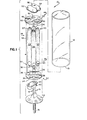
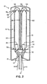
- FIG. 1 a compact fluorescent lamp 10 having an outer, light transmissive, glass envelope 12 which is hermetically sealed at its end 13 to a flare 14 which includes lead-in wires 16 and exhaust tubulations 18.
- An arc generating and sustaining atmosphere e.g., about 20 mg of mercury and argon at a pressure 3 torr. is provided within envelope 12.
- an assembly 19 comprised of a plurality of elongated tubes 20. 22. 24 and 26 each having first ends 28 and second ends 30.
- These tubes are coated on their interior surface with a suitable U.V. excitable phosphor, e.g., a calcium halophosphate activated with antimony and manganese, or any operative phosphor or combination of phosphors.
- a suitable U.V. excitable phosphor e.g., a calcium halophosphate activated with antimony and manganese, or any operative phosphor or combination of phosphors.
- the phosphors can be applied by any suitable method, including those used to coat conventional fluorescent tubes.
- the tubes 20. 22, 24. and 26 are formed from T5 tubing and are about four inches long (approx. 10.16 cm). For ease in coating a single. long tube. say three long (approx. 1 m) can be coated and subsequently cut into appropriate lengths.
- a first arc directing means 32 is associated with first ends 28 of tubes 20. 22. 24 and 26. and comprises a first base member 34 having apertures 36 therein for receiving the first ends 28 of the tubes.
- Two of the tubes e.g.. 20 and 22. have their first ends 28 provided with electrodes 38 and 40. While these electrodes may be sealed into the tube ends in a conventional manner for convenience in handling, it is not necessary that a hermetic seal be formed, and the electrodes may be mounted within the tubes in any desired manner.
- a single arc director 42 is positioned on the underside of first base member 34 and covers the apertures into which the first ends 28 of tubes 24 and 26 are fitted. As shown, arc director 42 is in the form of a rectangular dish having a peripheral rim 44 about its open side. The arc director 42 is affixed to the underside by any suitable means, if it is formed separated from first base member 34, although the entire arc directing means 34 can be formed as a one piece unit.
- a second arc directing means 46 is associated with the second ends 30 of tubes 20. 22. 24 and 26 and comprises a second base member 48 having apertures 50 therein for receiving the second ends,30 of the tubes.
- the upper side of second base member 48 i.e., the side remote from the tubes, has two arc directors 52 and 54 positioned thereon.
- the arc directors 52 and 54 can be of the same construction as arc director 42.
- Arc director 52 encompasses the apertures receiving the second ends 30 of the tubes 20 and 24; and
- arc director 54 encompasses the apertures receiving the second ends 30 of the tubes 22 and 26.
- a connecting rod 56 extends between the first base member 34 and the second base member 48 and is affixed thereto, thus securing the assembly 19 together as a unit.
- the ends 28 and 30 of tubes 20. 22. 24 and 26 within the apertures 36 and 50 in an arc tight manner are formed with arc tight, depth regulating means 55 and 57 respectively.
- the means 55 and 57 comprise a reduced diameter portion formed on the terminus of the ends; the reduced diameter portion being connected to the given diameter of the tube by a radius.
- the means 55 and 57 could also be formed substantially frusto-conical.
- the apertures 36 and 50 have diameters greater than the reduced diameter and less than the given diameter of the tubes. This construction allows the ends of the tubes to penetrate the arc directors 42. 52 and 54 a sufficient distance for good seating and to allow the formation of an arc tight but atmosphere permeable fit. Further, this construction allows this desired fit within the limits of normal manufacturing tolerances between the tube ends and the apertures.
- At least one of the arc directors, e.g.. 54, is provided with an opening 58 therein.
- the arc will proceed, during each half cycle. from electrode 38 up the length of tube 20. across arc director 52, down tube 24, across arc director 42, up tube 26. across arc director 54, and down tube 22 to electrode.
- the direction will be reversed.
- Lamps constructed as described above have many advantages over those of the prior art. Simple, mechanical joints are employed together with novel arc directors, to form a long arc path in a compact lamp.
- the lamps can be constructed with a range of tube quantities and tube lengths giving flexibility to the size and output of the lamps.
- the lamps can be operated at high electrical loadings because the arc directing means provide a shielding effect. thus allowing the mercury vapor pressure to be held at a lower temperature.
- the tubes can be constructed from a variety of materials since no seals are required internally.
- each of the tubes is a separate entity, each of the tubes can have a different phosphor applied thereto, thus allowing for color blending.
- the lamps are adaptable to high speed manufacturing techniques because of the mechanical nature of the inner assembly.
- the second arc directing means 46 can be eliminated by employing two "U" shaped tubes, as shown in S.N. 481,230, filed April 1. 1983 and assigned to the assignee of the present invention.
- small glass tubing can be used to surround them.
Landscapes
- Vessels And Coating Films For Discharge Lamps (AREA)
Applications Claiming Priority (2)
| Application Number | Priority Date | Filing Date | Title |
|---|---|---|---|
| US538407 | 1983-10-03 | ||
| US06/538,407 US4539510A (en) | 1983-10-03 | 1983-10-03 | Compact fluorescent lamp |
Publications (3)
| Publication Number | Publication Date |
|---|---|
| EP0136685A2 true EP0136685A2 (de) | 1985-04-10 |
| EP0136685A3 EP0136685A3 (en) | 1986-01-08 |
| EP0136685B1 EP0136685B1 (de) | 1988-12-14 |
Family
ID=24146818
Family Applications (1)
| Application Number | Title | Priority Date | Filing Date |
|---|---|---|---|
| EP84111689A Expired EP0136685B1 (de) | 1983-10-03 | 1984-09-29 | Kompakte Leuchtstofflampe |
Country Status (5)
| Country | Link |
|---|---|
| US (1) | US4539510A (de) |
| EP (1) | EP0136685B1 (de) |
| JP (1) | JPS6097539A (de) |
| CA (1) | CA1221723A (de) |
| DE (1) | DE3475676D1 (de) |
Cited By (2)
| Publication number | Priority date | Publication date | Assignee | Title |
|---|---|---|---|---|
| EP0233664A1 (de) * | 1986-02-03 | 1987-08-26 | Koninklijke Philips Electronics N.V. | Niederdruckquecksilberdampfentladungslampe |
| EP0278477A3 (en) * | 1987-02-10 | 1990-06-20 | Matsushita Electronics Corporation | Fluorescent lamp device with incadescent bulb type base cap |
Families Citing this family (6)
| Publication number | Priority date | Publication date | Assignee | Title |
|---|---|---|---|---|
| US4853591A (en) * | 1983-11-25 | 1989-08-01 | Patent Treuhand Gesellschaft Fur Elektrische Gluhlampen Mbh | Multiple-tube compact low-pressure discharge fluorescent lamp |
| US4698040A (en) * | 1986-10-22 | 1987-10-06 | Gte Products Corporation | Method of making arc discharge lamps |
| US5055735A (en) * | 1989-01-30 | 1991-10-08 | U.S. Philips Corporation | High pressure discharge lamp having improved containment structure |
| FR2648617A1 (fr) * | 1989-06-17 | 1990-12-21 | Toshiba Lighting Technology Co | Lampe fluorescente |
| US5023506A (en) * | 1989-12-28 | 1991-06-11 | North American Philips Corporation | Explosion proof high pressure discharge lamp |
| US20090015129A1 (en) * | 2007-07-12 | 2009-01-15 | Noam Arye | Method and device for a compact fluorescent bulb |
Family Cites Families (3)
| Publication number | Priority date | Publication date | Assignee | Title |
|---|---|---|---|---|
| FR1060766A (fr) * | 1950-11-28 | 1954-04-06 | Acec | Lampes fluorescentes de courte longueur et de grande intensité lumineuse |
| US4208618A (en) * | 1978-09-20 | 1980-06-17 | Westinghouse Electric Corp. | Compact single-ended fluorescent lamp |
| JPS5744958A (en) * | 1980-08-29 | 1982-03-13 | Matsushita Electric Works Ltd | Low pressure discharge lamp |
-
1983
- 1983-10-03 US US06/538,407 patent/US4539510A/en not_active Expired - Fee Related
-
1984
- 1984-09-28 CA CA000464358A patent/CA1221723A/en not_active Expired
- 1984-09-29 DE DE8484111689T patent/DE3475676D1/de not_active Expired
- 1984-09-29 EP EP84111689A patent/EP0136685B1/de not_active Expired
- 1984-10-02 JP JP59205702A patent/JPS6097539A/ja active Pending
Cited By (2)
| Publication number | Priority date | Publication date | Assignee | Title |
|---|---|---|---|---|
| EP0233664A1 (de) * | 1986-02-03 | 1987-08-26 | Koninklijke Philips Electronics N.V. | Niederdruckquecksilberdampfentladungslampe |
| EP0278477A3 (en) * | 1987-02-10 | 1990-06-20 | Matsushita Electronics Corporation | Fluorescent lamp device with incadescent bulb type base cap |
Also Published As
| Publication number | Publication date |
|---|---|
| US4539510A (en) | 1985-09-03 |
| JPS6097539A (ja) | 1985-05-31 |
| EP0136685A3 (en) | 1986-01-08 |
| DE3475676D1 (en) | 1989-01-19 |
| EP0136685B1 (de) | 1988-12-14 |
| CA1221723A (en) | 1987-05-12 |
Similar Documents
| Publication | Publication Date | Title |
|---|---|---|
| US4393325A (en) | Low-pressure mercury vapor discharge lamp with mercury amalgam | |
| US4527089A (en) | Compact fluorescent lamp | |
| GB1578246A (en) | Fluorescent lighting | |
| US4978884A (en) | Metal halide discharge lamp having low color temperature and improved color rendition | |
| US4539510A (en) | Compact fluorescent lamp | |
| EP0233664B1 (de) | Niederdruckquecksilberdampfentladungslampe | |
| US4524301A (en) | Compact fluorescent lamps | |
| EP0121428B1 (de) | Kompakt Fluoreszenzentladungslampe mit glasbeschichtetem metallischem Entladungsführungselement | |
| EP0156384B1 (de) | Elektrodenaufstellung und Kapselentwurf für einseitig gesockelte Niederleistungsmetallhalogenidlampen | |
| US4575344A (en) | Metal arc director for compact fluorescent lamp | |
| US4527088A (en) | Metal arc director for compact fluorescent lamp | |
| US4521837A (en) | Compact fluorescent lamp having increased light output | |
| US4600856A (en) | Compact low pressure arc discharge lamp | |
| US4617489A (en) | Compact fluorescent lamp having internal thermally actuable means | |
| EP0156385A2 (de) | Elektrodenaufstellung und Kapselentwurf für einseitig gesockelte Niederleistungsmetallhalogenidlampen | |
| US4560357A (en) | Method for sealing arc discharge lamps | |
| GB2157883A (en) | Low-pressure mercury vapour discharge lamp | |
| EP0173235B1 (de) | Metallhalogenidlampe mit niedrigem Vermögen | |
| CA1213933A (en) | Metal arc director for compact fluorescent lamp | |
| US4598230A (en) | Compact fluorescent lamp having thermally actuable means | |
| EP0902458A2 (de) | Niederleistungslampe mit geformter Bogenröhre in Aluminiumsilikat Aussenmantel | |
| EP0127475A1 (de) | Zweiseitig gesockelte Kompakt-Leuchtstofflampe | |
| US2961565A (en) | Low-pressure discharge lamp | |
| US4678520A (en) | Electrical lead-ins for use for arc sustaining atmospheres | |
| US4689031A (en) | Method for sealing arc discharge lamps |
Legal Events
| Date | Code | Title | Description |
|---|---|---|---|
| PUAI | Public reference made under article 153(3) epc to a published international application that has entered the european phase |
Free format text: ORIGINAL CODE: 0009012 |
|
| 17P | Request for examination filed |
Effective date: 19840929 |
|
| AK | Designated contracting states |
Designated state(s): BE DE FR GB IT NL |
|
| PUAL | Search report despatched |
Free format text: ORIGINAL CODE: 0009013 |
|
| AK | Designated contracting states |
Designated state(s): BE DE FR GB IT NL |
|
| 17Q | First examination report despatched |
Effective date: 19870227 |
|
| ITF | It: translation for a ep patent filed | ||
| GRAA | (expected) grant |
Free format text: ORIGINAL CODE: 0009210 |
|
| AK | Designated contracting states |
Kind code of ref document: B1 Designated state(s): BE DE FR GB IT NL |
|
| REF | Corresponds to: |
Ref document number: 3475676 Country of ref document: DE Date of ref document: 19890119 |
|
| ET | Fr: translation filed | ||
| PG25 | Lapsed in a contracting state [announced via postgrant information from national office to epo] |
Ref country code: GB Effective date: 19890929 |
|
| PG25 | Lapsed in a contracting state [announced via postgrant information from national office to epo] |
Ref country code: BE Effective date: 19890930 |
|
| PLBE | No opposition filed within time limit |
Free format text: ORIGINAL CODE: 0009261 |
|
| STAA | Information on the status of an ep patent application or granted ep patent |
Free format text: STATUS: NO OPPOSITION FILED WITHIN TIME LIMIT |
|
| 26N | No opposition filed | ||
| BERE | Be: lapsed |
Owner name: GTE PRODUCTS CORP. Effective date: 19890930 |
|
| PG25 | Lapsed in a contracting state [announced via postgrant information from national office to epo] |
Ref country code: NL Effective date: 19900401 |
|
| NLV4 | Nl: lapsed or anulled due to non-payment of the annual fee | ||
| GBPC | Gb: european patent ceased through non-payment of renewal fee | ||
| PG25 | Lapsed in a contracting state [announced via postgrant information from national office to epo] |
Ref country code: FR Effective date: 19900531 |
|
| PG25 | Lapsed in a contracting state [announced via postgrant information from national office to epo] |
Ref country code: DE Effective date: 19900601 |
|
| REG | Reference to a national code |
Ref country code: FR Ref legal event code: ST |