EP0136746B1 - Appareil d'impression - Google Patents
Appareil d'impression Download PDFInfo
- Publication number
- EP0136746B1 EP0136746B1 EP84201226A EP84201226A EP0136746B1 EP 0136746 B1 EP0136746 B1 EP 0136746B1 EP 84201226 A EP84201226 A EP 84201226A EP 84201226 A EP84201226 A EP 84201226A EP 0136746 B1 EP0136746 B1 EP 0136746B1
- Authority
- EP
- European Patent Office
- Prior art keywords
- text roll
- printing apparatus
- text
- roll
- stop block
- Prior art date
- Legal status (The legal status is an assumption and is not a legal conclusion. Google has not performed a legal analysis and makes no representation as to the accuracy of the status listed.)
- Expired
Links
Images


Classifications
-
- B—PERFORMING OPERATIONS; TRANSPORTING
- B41—PRINTING; LINING MACHINES; TYPEWRITERS; STAMPS
- B41F—PRINTING MACHINES OR PRESSES
- B41F17/00—Printing apparatus or machines of special types or for particular purposes, not otherwise provided for
- B41F17/24—Printing apparatus or machines of special types or for particular purposes, not otherwise provided for for printing on flat surfaces of polyhedral articles
- B41F17/26—Printing apparatus or machines of special types or for particular purposes, not otherwise provided for for printing on flat surfaces of polyhedral articles by rolling contact
Definitions
- the invention relates to a printing apparatus for applying a coding on a surface which is transported past the printing apparatus, comprising a text roll for the coding characters supported by a frame and rotatably mounted on a shaft, which text roll can be driven by the passing surface, and a rotatable inking means for inking the coding characters, wherein the text roll is movable backwards and forwards in radial direction, a driving means being provided for moving the text roll in radial direction from a rest position, in which the text roll is completely free of the surface to be coded, to a working position, in which the text roll can engage the surface to be coded, when a surface to be coded comes up to the text roll, and vice versa after applying the coding.
- a printing apparatus of this type is described in US-A-3 294 015.
- the text roll is driven by the passing surface to be coded only.
- the text roll can be arranged to print for two or more cycles for each complete revolution by means of cam pins disposed at the circumference of the text roll and cooperating with a switch.
- This switch operates the driving means to radially return the text roll to the rest position and a brake means to stop a rotational movement of the text roll. Therefore, if the length of the coding is less than the corresponding circumferential part of the text roll, the text roll has to be maintained in its working position until the cam pin reaches the switch.
- GB-A-858 879 discloses a printing apparatus having a text roll which is rotationally driven by a motor through a complicated clutch mechanism. Due to this clutch mechanism the rotational speed of the text roll may adapt to the linear speed of the surface to be coded. Between coding cycles rotation of the text roll is prevented by a latch mechanism.
- US-A-3 092 019 discloses a similar printing apparatus having a text roll which can be rotationally driven by a motor through a clutch mechanism. After each printing cycle the text roll is stopped in a rest position by a locking member.
- the shaft of the text roll is borne in bearing blocks which are movable in a radial direction against the action of a spring which will allow for unevenness in the surface being coded or slight inaccuracy in the positioning of the frame relative to the article path.
- DE-A-2 653 069 describes a printing apparatus having a plate-like printing head which is movable in a vertical direction by a driving means. During the first part of this downward movement the printing head is rotated by the same driving means along 90° to bring the printing head from a vertical into a horizontal position. Subsequently, the printing head is pressed upon the surface to be coded. During the backward movement the printing head is rotated from the horizontal to the vertical position again.
- the invention aims to provide a printing apparatus according to the preamble of claim 1 wherein the text roll can be returned into the rest position as soon as the required coding is applied without a special driving means for the text roll being required.
- the printing apparatus is characterized in that the same driving means is adapted to rotate the text roll from the rest position to the working position during the radial movement of the text roll, and to rotate the text roll to the rest position from an end position reached by the coding operation.
- the inking means is located in rotational direction of the text roll between the rest position and the working position.
- the driving means operates a stop block movable backwards and forwards, said stop block having a first recess adapted to cooperate with a pin of the text roll, wherein the shaft of the text roll is borne in a bearing block movable backwards and forwards in the same direction as the stop.
- said bearing block being movable by the stop block, wherein said stop block is adapted to rotate the text roll to the working position by means of the pin during the forward motion and to move the bearing block together with the text roll during the last part of the forward motion, whereas the bearing block is returned by a return means during the first part of the backward motion of the stop block, the stop block further being coupled by a coupling member to the text roll for rotating the text roll to the rest position determined by said recess during the remaining part of the backward motion.
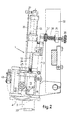
- a printing apparatus 1 for applying a coding on a surface which is transported past the printing apparatus, for example the upper surface of a schematically indicated box 2.
- the printing apparatus 1 comprises a text roll 4 supported by a frame 3, which text roll 4 can be driven by the passing box 2.
- the text roll 4 is provided with a peripheral covering 5 with slots 6 in which the desired coding characters can be fixed.
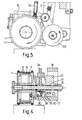
- the text roll 4 is rotatably mounted on a shaft 8 by means of a freewheel clutch 7, which shaft 8 is rotatably mounted in a bearing block 10 by means of a freewheel clutch 9. Thereby the text roll 4 and the shaft 8 can only rotate in the direction indicated by an arrow in fig. 5.
- the printing apparatus 1 is further provided with a driving menas made as a pneumatic double operating cylinder piston assembly 11, by means of which the text roll 4 is rotatable and movable in radial direction.
- a driving menas made as a pneumatic double operating cylinder piston assembly 11, by means of which the text roll 4 is rotatable and movable in radial direction.
- the piston rod 12 of the cylinder piston assembly 11 is equipped with a stop block 13 movable backwards and forwards, said stop block 13 having a first recess 14 cooperating with a pin 15 carried by the text roll 4.
- the bearing block 10 is mounted movably in the same direction as the stop block 13 backwards and forwards between an upper plate 16 and a lower plate 17.
- the bearing block 10 is guided by a guiding rod 18.
- the bearing block 10 is movable by means of the stop block 13 because the stop block 13 has a recess 19 which cooperates with a pin 20 carried by the bearing block 10.
- the movement of the stop block 13 is guided by a ball bearing 21 mounted in the frame 3, which ball bearing 21 engages a slot formed in the stop block 13 and indicated by a dotted line.
- the cylinder piston assembly 11 is supported by the frame 3 rotatably on a pin 22, wherein a bolt 23 exerts a force on the cylinder piston assembly 11 in such a manner that the stop block 13 is pressed against the ball bearing 21.
- the stop block 13 is further coupled with the text roll 4 by means of a driving belt 24, one end of which is fixed in a protruding arm 25 of the stop block 13, while the other end is connected with the frame 3 through a spring 26.
- a protruding pin 27 is fixed at the upper side of the cylinder piston assembly 11.
- the driving belt 24 is led along a pulley 28 and extends through a bore 29 formed in the arm 25.
- the pulley 28 is coupled with the shaft 8 of the text roll 4 by means of a friction coupling 30.
- the friction coupling 30 shown in the drawings consists of an 0-ring enclosed between the pulley 28 and the shaft 8. However, the friction coupling can be made in any other suitable manner.
- the frame 3 of the printing appartus 1 is connected with a support arm 32 rotatable on a pin 31, which support arm 32 is mountable on a support 33 mounted above the path of the surface to be coded.
- the frame 3 carries a bolt 34 one end of which projects through a guiding arm 35 of the support arm 32, which end carries a nut 36.
- a spring 38 Between the guiding arm 35 and a nut 37 lying on the bolt 34 near the frame 3 lies a spring 38.
- the frame 3 of the printing means 1 can be pivoted upwardly against the action of the spring 38 by the product to be coded, as will be described hereafter.
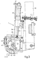
- the stop block 13 Due to the energizing of the cylinder piston assembly 11 the stop block 13 is moved downwards, wherein the text roll 4 is rotated by means of the pin 15 until the pin strikes a stop 40 carried by the frame 3. During the further downward motion of the stop block 13 the bearing block 10 is also moved downwards by means of the pin 20. Thereby the text roll 4 reaches the working position indicated in fig. 2 by a dotted line, in which working position the text roll 4 can engage the surface to be coded and the first coding character which lies in radial direction substantially at the location of the pin 15, is in the tangent plane of the text roll 4 and the surface to be coded.
- the cylinder piston assembly 11 should be energized for the backward motion.
- the text roll 4 carries a switching cam 41 fixed on a ring 42 rotatable in circumferential direction and provided at the side of the text roll 4 directed to the bearing block 10.
- the ring 42 is adjusted in such a manner that the switching cam 41 operates a switching means 43 as soon as the last coding character is applied and thus the text roll 4 is in an end position in respect of the coding operation.
- the switching means 43 energizes the cylinder piston assembly 11 for the backward motion.
- the bearing block 10 is returned by a spring 44 which is provided around the guiding rod 18 between the bearing block 10 and the lower plate 17.
- the text roll 4 is disengaged from the coded surface of the product 2.
- the shaft 8 is driven by the driving belt 24, so that due to the freewheel clutch 7 the text roll 4 will rotate with the shaft and will finally reach the rest position of fig. 1. It is not possible that the text roll 4 will rotate backwards due to the occurring reaction forces as this is prevented by the freewheel clutches 7 and 9.
- the angular distance along which the text roll 4 has to be rotated to reach the rest position depends on the length in circumferential direction of the coding to be applied.
- the distance along which the driving belt 24 is moved during the backward motion is such that the text roll 4 can reach the rest position under all circumstances.
- the pulley 28 can slip with respect to the shaft 8 by the application of the friction coupling 30.
- the frame 3 will be pivoted to the position of fig. 1 by the spring 38.
- FIG. 6 shows an alternative embodiment of the printing appartus 1 which mainly corresponds to the embodiment of fig. 1, wherein however a modified stop block 46 is provided.
- the stop block 46 comprises a pawl 47 which is pivotable against the action of a spring 48. The movable end of the pawl 47 adjoins the recess 14.
- the pin 15 of the text roll 4 would strike the stop block 46 before this stop block 46 has reached its rest position, the pin 15 will now be resiliently received by the pawl 47.
- the pin 15 can reach the recess 14 due to the pivotable mounting of the pawl 47.
- the printing apparatus 1 is provided with a rotatable inking means 45 for inking the coding characters disposed on the text roll 4. Seen in the rotational direction of the text roll 4 the inking means 45 is located between the rest position and the working position of the text roll 4. Thereby the first coding characters are already inked during rotating the text roll 4 from the rest position to the working position.
- the size of the text roll can be chosen independent of the surface to be coded, while the printing apparatus is moreover adapted to apply codings on packagings which are still contained in a material web.
- pneumatic cylinder piston assembly 11 can be replaced by any other suitable driving means.
Landscapes
- Rotary Presses (AREA)
- Inking, Control Or Cleaning Of Printing Machines (AREA)
- Particle Formation And Scattering Control In Inkjet Printers (AREA)
- Massaging Devices (AREA)
- Power Steering Mechanism (AREA)
- Confectionery (AREA)
Claims (11)
Priority Applications (1)
| Application Number | Priority Date | Filing Date | Title |
|---|---|---|---|
| AT84201226T ATE30699T1 (de) | 1983-08-31 | 1984-08-24 | Druckapparat. |
Applications Claiming Priority (2)
| Application Number | Priority Date | Filing Date | Title |
|---|---|---|---|
| NL8303030A NL8303030A (nl) | 1983-08-31 | 1983-08-31 | Drukapparaat. |
| NL8303030 | 1983-08-31 |
Publications (2)
| Publication Number | Publication Date |
|---|---|
| EP0136746A1 EP0136746A1 (fr) | 1985-04-10 |
| EP0136746B1 true EP0136746B1 (fr) | 1987-11-11 |
Family
ID=19842328
Family Applications (1)
| Application Number | Title | Priority Date | Filing Date |
|---|---|---|---|
| EP84201226A Expired EP0136746B1 (fr) | 1983-08-31 | 1984-08-24 | Appareil d'impression |
Country Status (6)
| Country | Link |
|---|---|
| US (1) | US4570537A (fr) |
| EP (1) | EP0136746B1 (fr) |
| JP (1) | JPS60192682A (fr) |
| AT (1) | ATE30699T1 (fr) |
| DE (1) | DE3467328D1 (fr) |
| NL (1) | NL8303030A (fr) |
Families Citing this family (3)
| Publication number | Priority date | Publication date | Assignee | Title |
|---|---|---|---|---|
| US4884505A (en) * | 1985-12-02 | 1989-12-05 | Porelon, Inc. | Method and apparatus for printing a light scannable image |
| US4768437A (en) * | 1986-06-03 | 1988-09-06 | Porelon, Inc. | High contrast printing material |
| DE3738779C1 (de) * | 1987-11-14 | 1988-07-07 | Hoesch Stahl Ag | Markiervorrichtung |
Family Cites Families (8)
| Publication number | Priority date | Publication date | Assignee | Title |
|---|---|---|---|---|
| US3092019A (en) * | 1956-11-23 | 1963-06-04 | Buskirk & Co Inc Van | Article marking |
| US2952204A (en) * | 1957-12-11 | 1960-09-13 | Weyerhaeuser Co | Method and means for marking articles and for processing marked articles |
| GB858879A (en) * | 1958-12-29 | 1961-01-18 | Gottscho Inc Adolph | Marking apparatus |
| US3112690A (en) * | 1961-10-26 | 1963-12-03 | Gottscho Inc Adolph | Marking apparatus |
| US3294015A (en) * | 1964-12-21 | 1966-12-27 | Pannier Corp | Article controlled actuating means for code pre-set wheel printer |
| US3327624A (en) * | 1965-05-24 | 1967-06-27 | Millard B Beaver | Marking apparatus for imprinting characters on articles being successively conveyed |
| US3808970A (en) * | 1968-11-25 | 1974-05-07 | P Delligatti | Biased return coding drum |
| DE2653069C3 (de) * | 1976-11-23 | 1981-07-16 | Metronic Gerätebau GmbH & Co, 8702 Veitshöchheim | Druckvorrichtung |
-
1983
- 1983-08-31 NL NL8303030A patent/NL8303030A/nl not_active Application Discontinuation
-
1984
- 1984-08-24 EP EP84201226A patent/EP0136746B1/fr not_active Expired
- 1984-08-24 AT AT84201226T patent/ATE30699T1/de active
- 1984-08-24 DE DE8484201226T patent/DE3467328D1/de not_active Expired
- 1984-08-29 US US06/645,613 patent/US4570537A/en not_active Expired - Fee Related
- 1984-08-31 JP JP59183615A patent/JPS60192682A/ja active Pending
Also Published As
| Publication number | Publication date |
|---|---|
| NL8303030A (nl) | 1985-03-18 |
| DE3467328D1 (en) | 1987-12-17 |
| JPS60192682A (ja) | 1985-10-01 |
| ATE30699T1 (de) | 1987-11-15 |
| EP0136746A1 (fr) | 1985-04-10 |
| US4570537A (en) | 1986-02-18 |
Similar Documents
| Publication | Publication Date | Title |
|---|---|---|
| US4033214A (en) | Blade sharpener | |
| US5207153A (en) | Apparatus for applying printed matter to objects | |
| US3738260A (en) | Article controlled bottom marking apparatus | |
| AU782076B2 (en) | Franking machine | |
| EP0136746B1 (fr) | Appareil d'impression | |
| US5906444A (en) | Bi-directional thermal printer and method therefor | |
| KR0155348B1 (ko) | 중량캐리지 고속위치설정장치 | |
| US3955458A (en) | Cutting apparatus with sharpener and sharpening method | |
| US4867058A (en) | Document transport and printing apparatus | |
| GB2091674A (en) | Blocking devices for conveyors | |
| EP0292524B1 (fr) | Embrayage a revolution unique | |
| US3960257A (en) | Apparatus for conveying and engraving tokens | |
| ES2066744T1 (es) | Subconjunto de accionamiento de mandril para decoradores de objetos cilindricos. | |
| CA1115122A (fr) | Tete d'impression a gros caracteres | |
| US4077318A (en) | Apparatus for printing upon moving sheets, paper or the like with automatic typesetting | |
| GB2154941A (en) | Rotating air cylinder driven hot ink marker | |
| US4098183A (en) | In-line printing device | |
| US4036127A (en) | Plate marking apparatus | |
| US4896595A (en) | Print head and backer plate assembly for carton marker | |
| US3882772A (en) | Method and apparatus for impressing identifying characters into metal bar stock | |
| US3814229A (en) | Data output printer | |
| US4579056A (en) | Printing mechanism | |
| EP0006689A1 (fr) | Machine à imprimer des étiquettes et procédé pour la formation de morceaux de ruban à partir d'un ruban sans fin | |
| KR850000261Y1 (ko) | 티켓(ticket)자동 발매기 | |
| JP2528139B2 (ja) | 金属輪転印刷機におけるシ―トプッシャ―装置 |
Legal Events
| Date | Code | Title | Description |
|---|---|---|---|
| PUAI | Public reference made under article 153(3) epc to a published international application that has entered the european phase |
Free format text: ORIGINAL CODE: 0009012 |
|
| AK | Designated contracting states |
Designated state(s): AT BE CH DE FR GB IT LI LU NL SE |
|
| 17P | Request for examination filed |
Effective date: 19850312 |
|
| R17P | Request for examination filed (corrected) |
Effective date: 19850312 |
|
| 17Q | First examination report despatched |
Effective date: 19860429 |
|
| GRAA | (expected) grant |
Free format text: ORIGINAL CODE: 0009210 |
|
| AK | Designated contracting states |
Kind code of ref document: B1 Designated state(s): AT BE CH DE FR GB IT LI LU NL SE |
|
| REF | Corresponds to: |
Ref document number: 30699 Country of ref document: AT Date of ref document: 19871115 Kind code of ref document: T |
|
| REF | Corresponds to: |
Ref document number: 3467328 Country of ref document: DE Date of ref document: 19871217 |
|
| ITF | It: translation for a ep patent filed | ||
| ET | Fr: translation filed | ||
| PG25 | Lapsed in a contracting state [announced via postgrant information from national office to epo] |
Ref country code: AT Effective date: 19880824 |
|
| PG25 | Lapsed in a contracting state [announced via postgrant information from national office to epo] |
Ref country code: SE Effective date: 19880825 |
|
| ITTA | It: last paid annual fee | ||
| PG25 | Lapsed in a contracting state [announced via postgrant information from national office to epo] |
Ref country code: LU Free format text: LAPSE BECAUSE OF NON-PAYMENT OF DUE FEES Effective date: 19880831 Ref country code: LI Effective date: 19880831 Ref country code: CH Effective date: 19880831 |
|
| PLBE | No opposition filed within time limit |
Free format text: ORIGINAL CODE: 0009261 |
|
| STAA | Information on the status of an ep patent application or granted ep patent |
Free format text: STATUS: NO OPPOSITION FILED WITHIN TIME LIMIT |
|
| 26N | No opposition filed | ||
| REG | Reference to a national code |
Ref country code: CH Ref legal event code: PL |
|
| PG25 | Lapsed in a contracting state [announced via postgrant information from national office to epo] |
Ref country code: GB Effective date: 19890824 |
|
| PG25 | Lapsed in a contracting state [announced via postgrant information from national office to epo] |
Ref country code: BE Effective date: 19890831 |
|
| BERE | Be: lapsed |
Owner name: B.V. KORTNOFAH Effective date: 19890831 |
|
| PG25 | Lapsed in a contracting state [announced via postgrant information from national office to epo] |
Ref country code: NL Effective date: 19900301 |
|
| NLV4 | Nl: lapsed or anulled due to non-payment of the annual fee | ||
| GBPC | Gb: european patent ceased through non-payment of renewal fee | ||
| PG25 | Lapsed in a contracting state [announced via postgrant information from national office to epo] |
Ref country code: FR Effective date: 19900427 |
|
| PG25 | Lapsed in a contracting state [announced via postgrant information from national office to epo] |
Ref country code: DE Effective date: 19900501 |
|
| REG | Reference to a national code |
Ref country code: FR Ref legal event code: ST |
|
| EUG | Se: european patent has lapsed |
Ref document number: 84201226.2 Effective date: 19890510 |