EP0136889A2 - Procédé et dispositif pour réduire le contenu en liquide d'une matière perméable au gaz - Google Patents
Procédé et dispositif pour réduire le contenu en liquide d'une matière perméable au gaz Download PDFInfo
- Publication number
- EP0136889A2 EP0136889A2 EP84306614A EP84306614A EP0136889A2 EP 0136889 A2 EP0136889 A2 EP 0136889A2 EP 84306614 A EP84306614 A EP 84306614A EP 84306614 A EP84306614 A EP 84306614A EP 0136889 A2 EP0136889 A2 EP 0136889A2
- Authority
- EP
- European Patent Office
- Prior art keywords
- tube
- frame
- gas
- permeable material
- slot
- Prior art date
- Legal status (The legal status is an assumption and is not a legal conclusion. Google has not performed a legal analysis and makes no representation as to the accuracy of the status listed.)
- Withdrawn
Links
Images
Classifications
-
- F—MECHANICAL ENGINEERING; LIGHTING; HEATING; WEAPONS; BLASTING
- F26—DRYING
- F26B—DRYING SOLID MATERIALS OR OBJECTS BY REMOVING LIQUID THEREFROM
- F26B13/00—Machines and apparatus for drying fabrics, fibres, yarns, or other materials in long lengths, with progressive movement
- F26B13/24—Arrangements of devices using drying processes not involving heating
- F26B13/30—Arrangements of devices using drying processes not involving heating for applying suction
-
- D—TEXTILES; PAPER
- D06—TREATMENT OF TEXTILES OR THE LIKE; LAUNDERING; FLEXIBLE MATERIALS NOT OTHERWISE PROVIDED FOR
- D06B—TREATING TEXTILE MATERIALS USING LIQUIDS, GASES OR VAPOURS
- D06B15/00—Removing liquids, gases or vapours from textile materials in association with treatment of the materials by liquids, gases or vapours
- D06B15/04—Removing liquids, gases or vapours from textile materials in association with treatment of the materials by liquids, gases or vapours by suction
Definitions
- This invention relates to a method of and apparatus for reducing the liquid (e.g. moisture) content of a gas-permeable material (e.g. a fabric) in tubular form.
- a gas-permeable material e.g. a fabric
- a method of reducing the liquid content of a tubular fabric is described in British Specification No. 2,004,998.
- a tube of fabric is passed through a surrounding frame comprising at least one hollow member connected to a source of suction.
- the surface of the frame presented to the tube is provided with elongate apertures which are inclined at a slight angle to the direction of movement of the tube of fabric through the frame.
- the elongate apertures are inclined at an angle of no more than 10° to the direction of movement of the tube of fabric. All parts of the surface of the tube of fabric receive the same treatment.
- this disadvantage is overcome in a method of reducing the liquid content of a gas-permeable material by passing a tube of the gas-permeable material through a frame which subjects the outer surface of the tube of gas-permeable material to suction via a slot in the frame, which method is characterised in that the slot is at least substantially continuous in the direction around the tube of gas-permeable material.
- the frame may be adjustable in size to correspond to the outer surface of the tube of gas-permeable material.
- the frame may be constituted by a tubular member surrounding the tube of gas-permeable material and thus providing an aperture through which the tube of gas-permeable material moves, the slot being constituted by a gap in the wall of the tubular member which defines the aperture.
- the slot may be partially closed with perforated material, such as a mesh or a sieve-like plate, which may be set back into the slot so as normally not to be in contact with the gas-permeable material passing through the frame.
- perforated material may present a concave surface to the gas-permeable material.
- An insert may be located within the tube of gas-permeable material so that as the latter moves over the insert, the tube is spread out to bring it into close proximity with the slot (eg with the wall defining the aperture in the frame).
- the pressure within the tube of gas-permeable material as it approaches the frame is greater than atmospheric and this will assist in expanding the tube as it approaches the slot (eg in adhering the tube closely to the wall defining the aperture in the frame).
- the width of the slot in the direction of movement of the tube of air permeable material past it, may be in the region of 100 mm.
- the invention includes apparatus for carrying out the method described above and fabric subjected to the method.
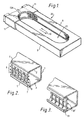
- a frame 20 of the apparatus according to the invention illustrated in Figure 1 comprises a tubular member comprising a duct 1 ( Figures 2 and 3) formed into a U-shaped member 9.
- the mouth of the U-shaped member 9 is closed by a further hollow part 11 of the tubular member constituting the frame 20 and the part 11 is slidable on the limbs of the U-shaped member 9.
- the frame 20 is adjustable to alter the size of the aperture 21 defined by the duct 1 and the part 11.
- the ducts 1 shown in Figures 2 and 3 are of square cross-section with upper and lower walls 2 and 3.
- One wall of each duct 1 is formed with a gap constituting a slot 6 bordered by lips 4 and 5.
- the wall containing the slot 6 of the duct 1 defines the aperture 21 in the frame 20.
- the part 11 is formed with a similar gap so that the slot 6 is substantially continuous around the inner wall of the frame 20.
- the entry 7 of the frame 20 (see Figures 2 and 3) is outwardly flared and thus the entry cross-section of the aperture 21 is larger than the cross-section at the lips 4 and 5.
- a perforated member constituted by a mesh 8 which presents a concave surface to the slot 6 and the aperture 21.
- Figure 3 shows an alternative flat mesh 8' inset with respect to the lips 4 and 5 of the duct 1 by spacers 13.
- the perforated member which partially closes the slot 6 may be constituted by a sieve-like apertured plate which may be concave like the mesh 8 or inset like the mesh 8'.
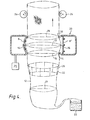
- Figure 4 shows schematically a tube 12 of air-permeable fabric 22 drawn upwardly (from a reservoir 23 thereof) by means 24 through the frame 20.
- the initial cross-section 13 of the tube 12 expands and within the frame 20, the tube barrels out under the influence of suction applied to the duct 1 and part 11 of the frame 20 by means 25 (and of the superatmospheric pressure created in the tube 12 as described below).
- the tube 12 has the cross-section 15.
- the tube 12 further expands to the cross-section 17 and is reduced at the level 18 to the cross-section 19. Because the mesh 8 (if. used) is concave and slightly inset and the mesh 8' (if used) is further inset within the duct 1, the tube 12, despite its expansion, does not, during normal operation of the apparatus, contact the mesh 8 or the mesh 8' or at least does not contact either mesh to such an extent as to generate any frictional conjunction deleterious to the fabric 22. However, if, for example, the speed of movement of the fabric 22 through the apparatus were to fall, or the fabric were to come to a halt so that the tension in the fabric became reduced to the extent that the fabric would otherwise be drawn into the slot 6, the mesh 8 or 8' would prevent that.
- the aperture 21 in the frame 20 may be elliptical, or, as in the example shown in Figure 1, generally rectangular with rounded ends. Since the overall size of the aperture 21 can be adjusted by means of the part 11, the aperture may be made to correspond in size to the size (within limits) of any particular tube of gas-permeable material which is to have its moisture content reduced by passage through the apparatus.
- an insert 26 for example in the form of a wire cage, which will be supported by the tube of air-permeable material itself, so that in moving over the insert, which remains relatively stationary, the tube is spread and expanded to bring it into close proximity with the wall of the duct 1 and part 11 which defines the aperture 21.
- the insert is, of course, shaped to correspond to the shape of the aperture 21 in order to achieve this.
- the tube 12 of air-permeable material may have within it, as it approaches the frame 20, water vapour and gas at a pressure higher than atmospheric.
- Such superatmospheric pressure may result from the introduction of gas into the tube of air-permeable material during another treatment, for example, passage through an upstream drying chamber in which gas is passed into the tube of air-permeable material through its wall, under pressure.
- the superatmospheric pressure may be the result of deliberate introduction of gas into the tube specifically for the purpose of producing the superatmospheric pressure.
- the gas may be introduced, for example, at a location downstream of the frame 20 in the direction of movement of the tube of air-permeable material yet cause an increase in the pressure of the gas within the tube 12 of air-permeable material extending upstream to the frame 20 and substantially beyond.
- the effect of the suction applied at the slot 6, together with the superatmospheric pressure within the tube of air-permeable material, and/or the presence of an insert within the tube of air-permeable material, causes the tube 12 of air-permeable material to adhere closely to, and possibly to come into practically airtight contact with, the lip 5 at the entry end of the duct 1 of the frame 20 and the lip 4 at the exit epd (and the equivalent parts of the part 11).
- the slot 6 may have a width, in the direction of movement of the tube 12 through the frame 20, of between 50 mm and 150 mm, for example in the region of 100 mm.
- the suction means 25 connected to the duct 1 (and part 11) of the apparatus in Figure 1 is preferably capable of applying an adjustable degree of suction at the slot 6.
- the suction means is capable of producing within the duct 1 a pressure of from 1.25 kPa to 5.00 kPa (5" to 20TM water gauge) below atmospheric pressure.
- the entire movement of gas into the duct 1 and part 11 is caused to take place from inside the tube 12 of air-permeable material.
- the gaseous flow is thus through the minute openings in the structure of the air-permeable material and will carry with it moisture held in the material.
- the slot 6 is substantially continuous around the inner wall of the duct 1 and the part 11, which together define the aperture 21. That is, the suction slot is continuous in the direction around the tube 12 of air-permeable material in Figure 4 and extends at least 50 mm in the length direction of the tube 12.
Landscapes
- Engineering & Computer Science (AREA)
- Textile Engineering (AREA)
- Mechanical Engineering (AREA)
- General Engineering & Computer Science (AREA)
- Treatment Of Fiber Materials (AREA)
- Physical Or Chemical Processes And Apparatus (AREA)
Applications Claiming Priority (2)
| Application Number | Priority Date | Filing Date | Title |
|---|---|---|---|
| GB8326291 | 1983-09-30 | ||
| GB838326291A GB8326291D0 (en) | 1983-09-30 | 1983-09-30 | Reducing liquid content of air-permeable material |
Publications (2)
| Publication Number | Publication Date |
|---|---|
| EP0136889A2 true EP0136889A2 (fr) | 1985-04-10 |
| EP0136889A3 EP0136889A3 (fr) | 1986-04-23 |
Family
ID=10549551
Family Applications (1)
| Application Number | Title | Priority Date | Filing Date |
|---|---|---|---|
| EP84306614A Withdrawn EP0136889A3 (fr) | 1983-09-30 | 1984-09-28 | Procédé et dispositif pour réduire le contenu en liquide d'une matière perméable au gaz |
Country Status (2)
| Country | Link |
|---|---|
| EP (1) | EP0136889A3 (fr) |
| GB (2) | GB8326291D0 (fr) |
Families Citing this family (1)
| Publication number | Priority date | Publication date | Assignee | Title |
|---|---|---|---|---|
| DE10112045B4 (de) * | 2001-03-14 | 2006-11-30 | Suchy Textilmaschinenbau Gmbh | Rundausbreiter für textile Schlauchware |
Family Cites Families (6)
| Publication number | Priority date | Publication date | Assignee | Title |
|---|---|---|---|---|
| GB588407A (en) * | 1945-04-16 | 1947-05-21 | Curt Marcell Maximillian Jelli | Improvements in suction hydro-extractors |
| GB2002503B (en) * | 1977-07-20 | 1982-06-23 | Merriman H | Method and equipment for the combined suction extracton and drying of tubular fabrics |
| GB2004998B (en) * | 1977-07-20 | 1982-02-17 | Merriman H | Method and equipment for the suction extraction of liquids from tubular fabrics and open with fabrics |
| GB2034869B (en) * | 1978-10-04 | 1983-03-02 | Courtaulds Ltd | Method of and apparatus for drying tubular fabric |
| DE2966566D1 (en) * | 1979-02-20 | 1984-03-01 | Courtaulds Plc | Method of, and apparatus for, reducing the liquid content of air-permeable material in tubular form |
| DE3048957C2 (de) * | 1980-12-24 | 1985-01-31 | Lindauer Dornier Gmbh, 8990 Lindau | Trockenanlage für textile Schlauchware |
-
1983
- 1983-09-30 GB GB838326291A patent/GB8326291D0/en active Pending
-
1984
- 1984-09-28 EP EP84306614A patent/EP0136889A3/fr not_active Withdrawn
- 1984-09-28 GB GB08424531A patent/GB2148472B/en not_active Expired
Also Published As
| Publication number | Publication date |
|---|---|
| GB2148472B (en) | 1987-06-03 |
| GB8326291D0 (en) | 1983-11-02 |
| GB8424531D0 (en) | 1984-11-07 |
| GB2148472A (en) | 1985-05-30 |
| EP0136889A3 (fr) | 1986-04-23 |
Similar Documents
| Publication | Publication Date | Title |
|---|---|---|
| CA1101899A (fr) | Systeme d'engagement de la feuille entre les calandres | |
| DE3272046D1 (en) | Method for cleaning particles from a web and apparatus therefor | |
| FI104099B (fi) | Menetelmä ja laite paperikoneella tai vastaavalla tai sen jälkikäsittelylaitteella pölyn poistamiseksi | |
| PL329786A1 (en) | Method of and apparatus for treating a filter material web | |
| JPS601257B2 (ja) | ウエブ浮動用空気柱装置 | |
| ES488981A1 (es) | Dispositivo para el tratamiento superficial de estructuras textiles continuas | |
| FI914384A0 (fi) | Menetelmä ja laite aineradan kuivamuodostukseen pitkäkuituisesta materiaalista | |
| KR20020097247A (ko) | 가스쿠션에 금속밴드를 가이드하는 장치 | |
| EP0136889A2 (fr) | Procédé et dispositif pour réduire le contenu en liquide d'une matière perméable au gaz | |
| JPH0310756B2 (fr) | ||
| US3812598A (en) | Apparatus for drying damp web material | |
| JPS634115B2 (fr) | ||
| CA1316668C (fr) | Ventilateur de poche de machine a papier | |
| SE7906863L (sv) | Luftmunstycke vid en torkningsanordning for lopande materialbanor | |
| US4691450A (en) | Method and apparatus for the removal of liquid from a running yarn | |
| PL348322A1 (en) | Method of and apparatus for making filters for tobacco industry products | |
| EP0014787B1 (fr) | Procédé et appareil de déshydratation d'un matériau, perméable à l'air, de forme tubulaire | |
| ES518571A0 (es) | Metodo y dispositivo para el perfeccionamiento de las tecnicas de formacion de velos de fibras. | |
| KR940701471A (ko) | 합성엔드리스 필라멘트의 제조방법 및 장치 | |
| JPH11508000A (ja) | 抄紙機において紙ウエブをロールの領域で安定化するための装置と方法 | |
| FI113973B (fi) | Menetelmä rainan tukemiseksi ja rainantuentalaite | |
| KR910007785A (ko) | 웨브의 말단부를 이송하는 이송장치 | |
| KR970704943A (ko) | 종이 또는 판지와 같은 재료의 연속 스트립을 코팅하기 위한 방법 및 장치 | |
| JP4109179B2 (ja) | 抄紙機における脱水処理装置 | |
| JPS5933698B2 (ja) | 織機 |
Legal Events
| Date | Code | Title | Description |
|---|---|---|---|
| PUAI | Public reference made under article 153(3) epc to a published international application that has entered the european phase |
Free format text: ORIGINAL CODE: 0009012 |
|
| AK | Designated contracting states |
Designated state(s): CH DE FR LI SE |
|
| PUAL | Search report despatched |
Free format text: ORIGINAL CODE: 0009013 |
|
| AK | Designated contracting states |
Kind code of ref document: A3 Designated state(s): CH DE FR LI SE |
|
| 17P | Request for examination filed |
Effective date: 19860816 |
|
| 17Q | First examination report despatched |
Effective date: 19870625 |
|
| STAA | Information on the status of an ep patent application or granted ep patent |
Free format text: STATUS: THE APPLICATION IS DEEMED TO BE WITHDRAWN |
|
| 18D | Application deemed to be withdrawn |
Effective date: 19871105 |
|
| RIN1 | Information on inventor provided before grant (corrected) |
Inventor name: MERRIMAN, HORACE BARTLETT Inventor name: LASZLO, AKOS |