EP0136895A2 - Selbstreinigende Verbindung - Google Patents
Selbstreinigende Verbindung Download PDFInfo
- Publication number
- EP0136895A2 EP0136895A2 EP84306645A EP84306645A EP0136895A2 EP 0136895 A2 EP0136895 A2 EP 0136895A2 EP 84306645 A EP84306645 A EP 84306645A EP 84306645 A EP84306645 A EP 84306645A EP 0136895 A2 EP0136895 A2 EP 0136895A2
- Authority
- EP
- European Patent Office
- Prior art keywords
- chamber
- joint
- tubular member
- passage
- air
- Prior art date
- Legal status (The legal status is an assumption and is not a legal conclusion. Google has not performed a legal analysis and makes no representation as to the accuracy of the status listed.)
- Withdrawn
Links
Images
Classifications
-
- A—HUMAN NECESSITIES
- A47—FURNITURE; DOMESTIC ARTICLES OR APPLIANCES; COFFEE MILLS; SPICE MILLS; SUCTION CLEANERS IN GENERAL
- A47L—DOMESTIC WASHING OR CLEANING; SUCTION CLEANERS IN GENERAL
- A47L9/00—Details or accessories of suction cleaners, e.g. mechanical means for controlling the suction or for effecting pulsating action; Storing devices specially adapted to suction cleaners or parts thereof; Carrying-vehicles specially adapted for suction cleaners
- A47L9/02—Nozzles
- A47L9/04—Nozzles with driven brushes or agitators
Definitions
- This invention relates to joints in air passages through which flows matter capable of abrading the joints, and more particularly to a vacuum cleaner power nozzle having an articulated joint in the air passage between the power nozzle body and the hose coupling thereof.
- the suction motor unit and the dust-collecting bag are housed in a body which rests movably on the floor.
- a flexible hose is connected at one end to an orifice in the body, and any of various cleaning attachments can be connected to the other end of the hose.
- a rigid section commonly referred to as a "wand,” can be interposed between the end of the flexible hose and the attachment.
- hose includes both the flexible and the rigid portions of the hose.
- the power nozzle which is designed primarily for use on rugs and carpets, has a separate motor within its body which drives a rotary device, such as a brush or beater, for agitating the carpet surface to loosen dirt and for separating matted-down fibers.
- the brush is disposed in the air passage through which the flow of suction air removes the loosened dirt.
- This air flow passage terminates in a coupling to which the hose is connected.
- an articulated joint is usually provided in the air flow passage at a point between the body and the coupling, so that the angle between the hose and the floor at the coupling is freely variable.
- An early joint of that type included a fork hinged to the rear of the body.
- the coupling depended from the fork.
- a flexible hose connected the air flow passage in the body to the coupling, passing between the legs of the fork. The fork and the coupling could thus be pivoted in a vertical plane without disrupting the air flow passage.
- a more recent joint of that type includes a chamber having walls defined by the body of the nozzle, and a tubular member having a portion disposed within the chamber.
- a second portion of the tubular member extends from an opening of the chamber and terminates in the coupling.
- the portion of the tubular member disposed within the chamber is movable about a horizontal axis extending from one side of the chamber to the other, so that the tubular member can be pivoted in a vertical plane.
- An opening in the portion of the tubular member within the chamber is configured so that the air passage remains open regardless of the pivot angle, yet the opening is never exposed outside the chamber.
- a means for preventing abrasion damage caused by dust in a plastic articulated joint, in the air flow passage of a vacuum cleaner power nozzle, of the type having a tubular member disposed within a chamber defined by the nozzle body.
- the power nozzle comprises a body having a passage for the flow of air, means within the passage, supported by the body, for agitating a surface to be cleaned, and power means for driving the surface agitation means.
- a joint in the air flow passage of the body comprises a chamber whose inner and outer walls are defined by the body and a tubular member having outer walls and having a first portion disposed within the chamber which is movable about an axis in the chamber between service and storage positions, and a second portion extending from the chamber and having a coupling for attaching a vacuum cleaner hose.
- the chamber has a recess in its inner walls for collecting any dust which enters between the outer wall of the first portion of the tubular member and the inner wall of the chamber. The recess is positioned so that accumulated dust is removed periodically by the flow of air through the passage.
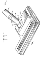
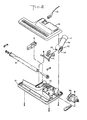
- FIGS. 1 through 3 A vacuum cleaner power nozzle 10 according to the present invention is shown in FIGS. 1 through 3.
- the nozzle is meant for use with a vacuum cleaner (not shown) which provides a flow of suction air through a suction hose (not shown) which is connected to the nozzle at coupling 11.
- Wand 12, shown connected to coupling 11, is an extension of the hose.
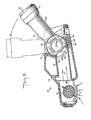
- the nozzle has a body 13 which has an air flow passage 30 through which the flow of suction air (indicated by the arrows A in FIG. 3) removes dust and dirt from the surface (not shown) being cleaned.
- a surface agitation device, such as rotary brush 31, supported by body 13 within passage 30, helps loosen the dirt from the surface.
- Agitation means 31 is powered by electric motor 32.
- the power to run electric motor 32 is conducted to nozzle 10 from the vacuum cleaner by nozzle power cord 14 which lies along or is molded in the suction hose.
- Joint 15 is provided in air flow passage 30 to allow such pivoting of wand 12 without disrupting the flow of suction air.
- Joint 15 includes a chamber 20 whose inner and outer walls are formed by nozzle body 13 and cover plate 21.
- Hollow tubular member 22 makes up the remainder of joint 15.
- Hollow first portion 23 of tubular member 22 is received in chamber 20.
- Hollow second portion 24 of tubular member 22 protrudes from the chamber and has an opening at coupling 11 at,the end thereof.
- Chamber 20 is open to air flow passage 30 at opening 33.
- First portion 23 has an opening 25 for registration with opening 33.
- First portion 23 can rotate about a horizontal side-to-side axis 23a in chamber 20 to allow the desired pivoting of second portion 24 and wand 12. Openings 25 and 33 are placed so that they remain in at least partial registration regardless of the position of tubular member 22. This allows air flow passage 30 to remain open between the surface to be cleaned and coupling 11 at all times.
- tubular member 22 is T-shaped with the cross bar of the T-shaped member serving as first portion 23 and the upright serving as second portion 24.
- the crossbar is closed at both ends.
- Dust which impinges on the portions of the outer wall of first portion 23 that are exposed to the air flow during use can be forced between the outer wall of first portion 23 and the inner wall of chamber 20 by pivoting of tubular member 22.
- the parts of joint 15 are made of plastic. Because dust is frequently harder than plastic, the dust which penetrates between the walls of first portion 23 and chamber 20 can scratch and grind the plastic. This can cause leakage of air around the joint and can also make pivoting of the joint difficult.
- one or more recesses 34, 35, 36 are provided in the inner wall of the chamber 20.
- the recesses are narrow elongated grooves parallel to axis 23a. Any dust which penetrates to the space between first portion 23 and chamber 20 will tend to accumulate in grooves 34, 35, 36.
- the pivoting of joint 15, which moves the dust into the space between part 23 and the lower wall of chamber 20 also sweeps the dust toward grooves 34, 35, 36.
- the grooves are placed so that as wand 12 is pivoted from a fully horizontal position to a fully upright position, grooves 34, 35, 36 are successively exposed to the flow of suction air, which removes the accumulated dust, thus cleaning the joint through normal use.
- wand 12 Under normal conditions of use, wand 12 is held between the horizontal and approximately a 45° angle, rising as the nozzle is drawn toward the user and falling as it is pushed away. Only when it is necessary for the user to pull the nozzle very close, or just before storage of the nozzle, does wand 12 rise to larger angles. Therefore, the sweeping action that causes dust to be brought into joint 15 will bring the greatest amount of dust to the area of groove 34.
- groove 34 will be the groove most frequently exposed to the air flow. Groove 35 will receive less dust and be exposed to the air less often, and groove 36 will receive the least dust and be exposed least often. Groove 34, which is the fastest filled, is also cleaned most frequently. In use, it is desirable to move wand 12 to the full upright "storage" position before turning off the suction motor of the vacuum cleaner, in order to clean out grooves 35 and 36.
- a vacuum cleaner power nozzle having a joint in which the abrasion damage caused by dust penetrates the joint is reduced, and in which the dust is removed through normal use of the power nozzle.
Landscapes
- Engineering & Computer Science (AREA)
- Mechanical Engineering (AREA)
- Nozzles For Electric Vacuum Cleaners (AREA)
- Electric Vacuum Cleaner (AREA)
Applications Claiming Priority (2)
| Application Number | Priority Date | Filing Date | Title |
|---|---|---|---|
| US06/537,643 US4521936A (en) | 1983-09-30 | 1983-09-30 | Self-cleaning joint |
| US537643 | 2004-01-19 |
Publications (2)
| Publication Number | Publication Date |
|---|---|
| EP0136895A2 true EP0136895A2 (de) | 1985-04-10 |
| EP0136895A3 EP0136895A3 (de) | 1986-09-24 |
Family
ID=24143510
Family Applications (1)
| Application Number | Title | Priority Date | Filing Date |
|---|---|---|---|
| EP84306645A Withdrawn EP0136895A3 (de) | 1983-09-30 | 1984-09-28 | Selbstreinigende Verbindung |
Country Status (2)
| Country | Link |
|---|---|
| US (1) | US4521936A (de) |
| EP (1) | EP0136895A3 (de) |
Families Citing this family (13)
| Publication number | Priority date | Publication date | Assignee | Title |
|---|---|---|---|---|
| DE8510161U1 (de) * | 1985-04-04 | 1985-06-05 | Siemens AG, 1000 Berlin und 8000 München | Kabelführung in das Gehäuse eines Gerätes |
| US5398373A (en) * | 1993-01-04 | 1995-03-21 | Bissell Inc. | Combination vacuum cleaner and water extractor power foot |
| US5483726A (en) * | 1993-01-04 | 1996-01-16 | Bissell Inc. | Combination vacuum cleaner and water extractor power foot |
| JP2561416B2 (ja) * | 1993-03-11 | 1996-12-11 | シャープ株式会社 | 電気掃除機の吸込口 |
| JP2573478B2 (ja) * | 1995-06-12 | 1997-01-22 | シャープ株式会社 | 電気掃除機の吸込口 |
| GB9927129D0 (en) | 1998-11-18 | 2000-01-12 | White Consolidated Ind Inc | Battery power combination vacuum cleaner |
| JP2001269294A (ja) * | 2000-03-23 | 2001-10-02 | Sharp Corp | 電気掃除機 |
| US6532622B2 (en) * | 2000-05-17 | 2003-03-18 | Daewoo Electronics Co., Ltd. | Brush head of vacuum cleaner |
| CN2495250Y (zh) * | 2001-07-19 | 2002-06-19 | 马美珍 | 外置式吸尘器电动滚动毛刷 |
| US20050066471A1 (en) * | 2003-09-30 | 2005-03-31 | Miller Paul R. | Color-coded cleaning nozzles and method of cleaning |
| US20060272122A1 (en) * | 2005-06-07 | 2006-12-07 | Dennis Butler | Vacuum brushroll edge cleaner |
| CN102639044B (zh) * | 2009-08-11 | 2014-12-24 | 碧洁家庭护理有限公司 | 具有辅助手持工具的直立式蒸汽拖把 |
| DE102010038026A1 (de) | 2010-10-06 | 2012-04-12 | Düpro AG | Staubsaugerdüse mit Magnetverriegelung |
Family Cites Families (19)
| Publication number | Priority date | Publication date | Assignee | Title |
|---|---|---|---|---|
| DE42230C (de) * | R. E. DONOVAN in Ormont Road, Rathmines, F. HAZLETT in 1 O'Connell Avenue, Dublin, und J. JOHNSTON in 50 Fieet Street Dublin | Einrichtung an einir mit der Glasbläserpfeife verbundenen Luftpumpe, um den Druck nach beendetem Blasen aufzuheben | ||
| US16585A (en) * | 1857-02-10 | Improvement in seed-planters | ||
| US1286321A (en) | 1916-10-09 | 1918-12-03 | Hoover Suction Sweeper Co | Brush. |
| US1552713A (en) * | 1922-10-26 | 1925-09-08 | William J Leary | Blackboard-erasing apparatus |
| NL28988C (de) * | 1929-07-17 | |||
| US2212942A (en) * | 1936-04-18 | 1940-08-27 | Electrolux Corp | Suction nozzle |
| US2202999A (en) * | 1937-03-03 | 1940-06-04 | Hoover Co | Suction cleaner |
| US2216934A (en) * | 1938-02-01 | 1940-10-08 | Electrolux Corp | Suction nozzle |
| US2295354A (en) * | 1940-01-12 | 1942-09-08 | Electrolux Corp | Suction nozzle |
| US2333409A (en) * | 1941-10-09 | 1943-11-02 | Electrolux Corp | Suction nozzle |
| US2371767A (en) * | 1944-06-12 | 1945-03-20 | Electrolux Corp | Vacuum cleaner |
| US2432670A (en) * | 1944-12-22 | 1947-12-16 | Electrolux Corp | Duplex suction nozzle with cover actuated valve |
| US2659099A (en) * | 1947-08-21 | 1953-11-17 | Ott Thomas Wellington | Vacuum cleaner head with handle controlled valve |
| DK113545B (da) * | 1966-11-01 | 1969-03-31 | W Jensen | Kugleventil. |
| US3943957A (en) * | 1975-03-17 | 1976-03-16 | Sanders Associates, Inc. | Flow control valve with internal rate of flow feedback |
| US4167801A (en) * | 1978-02-24 | 1979-09-18 | Royal Appliance Manufacturing Company | Suction cleaner power nozzle construction |
| US4199839A (en) * | 1978-10-12 | 1980-04-29 | Health-Mor, Inc. | Suction cleaner power nozzle construction |
| DE3131379A1 (de) * | 1981-08-07 | 1983-02-24 | Düpro AG, 8590 Romanshorn | Gelenkverbindung fuer staubsaugerduese |
| US4447930A (en) * | 1982-12-27 | 1984-05-15 | The Singer Company | Power head unit for carpet cleaning |
-
1983
- 1983-09-30 US US06/537,643 patent/US4521936A/en not_active Expired - Fee Related
-
1984
- 1984-09-28 EP EP84306645A patent/EP0136895A3/de not_active Withdrawn
Also Published As
| Publication number | Publication date |
|---|---|
| US4521936A (en) | 1985-06-11 |
| EP0136895A3 (de) | 1986-09-24 |
Similar Documents
| Publication | Publication Date | Title |
|---|---|---|
| US5903955A (en) | Upright vacuum cleaner | |
| US5722112A (en) | Vacuum assisted broom | |
| US5347679A (en) | Stick type vacuum cleaner | |
| US5504970A (en) | Hand-held vacuum cleaner | |
| US7124467B2 (en) | Edge cleaning system for vacuum cleaner | |
| CA1159610A (en) | Vacuum cleaning appliances | |
| US6514356B2 (en) | Edge cleaner for vacuum cleaner | |
| KR100430041B1 (ko) | 전기소제기 | |
| AU2018227581B2 (en) | Vacuum cleaner including a removable canister assembly | |
| US4521936A (en) | Self-cleaning joint | |
| US6029311A (en) | Vacuum assisted broom | |
| US5099545A (en) | Vacuum cleaner including a squeegee | |
| GB2450600A (en) | Vacuum cleaner | |
| US6772477B2 (en) | Floor nozzle for a vacuum cleaner | |
| US7290309B2 (en) | Cleaning head for a vacuum cleaner with edge cleaning bristles | |
| US4549328A (en) | Convertible vacuum and powder carpet cleaner | |
| AU2002231965A1 (en) | A cleaning head for a vacuum cleaner | |
| US7553347B2 (en) | Dust separator/collector assembly for suction cleaner | |
| US7272871B1 (en) | Dirt vessel equipped with cleaning plunger | |
| GB2308540A (en) | Multipurpose auxiliary brush | |
| KR20050061709A (ko) | 진공 청소기용 물걸레 청소용구 | |
| KR101108047B1 (ko) | 로봇 청소기 | |
| EP4426175A2 (de) | Bodenreinigungsgerät | |
| CN121817723A (zh) | 具有用于基于旋风的系统的旋转碎屑偏转板的清洁设备 | |
| JP4028784B2 (ja) | 吸込口体および電気掃除機 |
Legal Events
| Date | Code | Title | Description |
|---|---|---|---|
| PUAI | Public reference made under article 153(3) epc to a published international application that has entered the european phase |
Free format text: ORIGINAL CODE: 0009012 |
|
| AK | Designated contracting states |
Designated state(s): DE FR GB SE |
|
| PUAL | Search report despatched |
Free format text: ORIGINAL CODE: 0009013 |
|
| AK | Designated contracting states |
Kind code of ref document: A3 Designated state(s): DE FR GB SE |
|
| STAA | Information on the status of an ep patent application or granted ep patent |
Free format text: STATUS: THE APPLICATION IS DEEMED TO BE WITHDRAWN |
|
| 18D | Application deemed to be withdrawn |
Effective date: 19870525 |
|
| RIN1 | Information on inventor provided before grant (corrected) |
Inventor name: MEDWED, PETER M. |