EP0136971A2 - Dispositif de freinage pour un métier à tisser - Google Patents
Dispositif de freinage pour un métier à tisser Download PDFInfo
- Publication number
- EP0136971A2 EP0136971A2 EP84810352A EP84810352A EP0136971A2 EP 0136971 A2 EP0136971 A2 EP 0136971A2 EP 84810352 A EP84810352 A EP 84810352A EP 84810352 A EP84810352 A EP 84810352A EP 0136971 A2 EP0136971 A2 EP 0136971A2
- Authority
- EP
- European Patent Office
- Prior art keywords
- braking device
- elastic body
- recesses
- brake
- brake band
- Prior art date
- Legal status (The legal status is an assumption and is not a legal conclusion. Google has not performed a legal analysis and makes no representation as to the accuracy of the status listed.)
- Granted
Links
Images

Classifications
-
- F—MECHANICAL ENGINEERING; LIGHTING; HEATING; WEAPONS; BLASTING
- F16—ENGINEERING ELEMENTS AND UNITS; GENERAL MEASURES FOR PRODUCING AND MAINTAINING EFFECTIVE FUNCTIONING OF MACHINES OR INSTALLATIONS; THERMAL INSULATION IN GENERAL
- F16D—COUPLINGS FOR TRANSMITTING ROTATION; CLUTCHES; BRAKES
- F16D49/00—Brakes with a braking member co-operating with the periphery of a drum, wheel-rim, or the like
- F16D49/08—Brakes with a braking member co-operating with the periphery of a drum, wheel-rim, or the like shaped as an encircling band extending over approximately 360 degrees
-
- D—TEXTILES; PAPER
- D03—WEAVING
- D03D—WOVEN FABRICS; METHODS OF WEAVING; LOOMS
- D03D51/00—Driving, starting, or stopping arrangements; Automatic stop motions
- D03D51/02—General arrangements of driving mechanism
Definitions
- the invention relates to a braking device for a weaving machine, with a brake band that can be pressed onto a rotating drum and that engages at least one brake lever, at least one end of the brake band being fastened to the brake lever via a pressurized elastic body.
- Such braking devices are known per se.
- the elastic body should ensure a certain buffer effect at the end of the brake band so that its stress is reduced.
- the buffer effect is unsatisfactory in the conventional elastic bodies. This is particularly the case with very fast braking operations, as are required in the event of malfunctions in high-speed, high-performance weaving machines. With such a malfunction, e.g. a shot error, it is necessary that the main shaft comes to a standstill within a few degrees. This results in a very heavy load on the brake bands and drive elements.
- the inertia is obviously too great for such rapid force developments, since the full bush acts as a rigid body. The result is that the brake bands often tear and have to be replaced.
- the drive elements to be braked are exposed to undesirable torsional vibrations.
- the object of the invention is to improve the braking device mentioned at the outset in such a way that even with extremely short braking times a sufficient buffer effect is achieved and thus safe operation with a long service life of the brake bands and drive elements is ensured.
- the measure serves that the elastic body has recesses at least on its pressurized part.
- the elastic body can be arranged in a sleeve on which the brake band acts. This ensures a particularly secure attachment of the brake band to elastic bodies of various shapes.
- the elastic body can be designed as a sleeve.
- the end of the brake band can grip the elastic sleeve directly.
- the elastic sleeve can be arranged eccentrically on a bolt connected to the brake lever. In this way, a particularly effective use of material from the bush can be achieved.
- the recesses can be in the thicker part of the elastic sleeve. An optimal buffer effect is achieved.
- the elastic body can be designed like a block. This has the advantage that the elastic bodies can be replaced relatively easily if necessary.
- the recesses can extend transversely to the longitudinal direction of the brake band. This has the advantage of a relatively simple manufacture of the recesses.
- the recesses can be groove-like. This gives the advantage of a particularly favorable spring or damping characteristic.
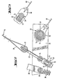
- One end loop 18 of the brake band 16 is connected via a bolt 20, a link 22 with an elastic bush 23 and a pin 24 to a double-walled brake lever 30 pivotably mounted on the axis 28 held by a bracket 26.
- the brake lever 30 has a pin 32 which, on the one hand, serves for fastening a tension spring 36 articulated on a spring bracket 34 and, on the other hand, serves as a point of application for a double-walled link 38, which is connected to a is connected to an eccentric locking lever 44 fastened by an axis 42 held by a bracket 40.
- the eccentric locking lever 44 engages with a pawl 46 which is connected in a rotationally fixed manner to a guard shaft 52 mounted in bearing bushes 48, 50.
- a lever 54 which can be acted upon via a guard rod 55, is also connected in a rotationally fixed manner to the guard shaft 52.
- a shoe 60 fastened by means of bolts 56, 58 sits on a wall of the brake lever 30 and is in contact with the roller lever 62 of a limit switch 64. This is connected via a line 66 to the main drive motor, not shown.
- the other end 68 of the brake band 16 is connected to the axle 28 via an elastic sleeve 72 arranged in a sleeve 70.
- the eccentrically designed elastic sleeve 72 has recesses in the form of axially parallel holes 74 on its pressurized part 73, while the elastic sleeve 23 has recesses in the form of radial bores 76 and circumferential grooves 78.
- the guard rod 55 moves in the direction of the arrow, the lever 54 causing the guard shaft 52 to rotate in the direction of the arrow shown in the figure.
- the pawl 46 is rotated upward in FIG. 1 so that the eccentric locking lever 44 can rotate clockwise under the action of the tension spring 36 or the link 38.
- the lever 30 is pivoted counterclockwise, the handlebar 22 with the end loop 18 of the brake band 16 being tightened by the lever 30 with the bolt 24.
- the spring 36 can be designed in this way be that fast braking with a relatively short braking distance is achieved, since the recesses 74, 76, 78 achieve an excellent damping effect. In particular, torsional vibrations of the main shaft or any secondary shafts are largely eliminated.
- the end of the brake band 68 is fastened to a sleeve 80, in which a block-like elastic body 82 is arranged instead of the elastic sleeve 72. This is relatively easy to replace.
- the recesses can also be formed as closed cavities or pores. Furthermore, the recesses can be filled with material of a different density.
Landscapes
- Engineering & Computer Science (AREA)
- General Engineering & Computer Science (AREA)
- Textile Engineering (AREA)
- Mechanical Engineering (AREA)
- Braking Arrangements (AREA)
- Looms (AREA)
Applications Claiming Priority (2)
| Application Number | Priority Date | Filing Date | Title |
|---|---|---|---|
| CH5440/83 | 1983-10-06 | ||
| CH5440/83A CH663971A5 (de) | 1983-10-06 | 1983-10-06 | Bremsvorrichtung fuer eine webmaschine. |
Publications (3)
| Publication Number | Publication Date |
|---|---|
| EP0136971A2 true EP0136971A2 (fr) | 1985-04-10 |
| EP0136971A3 EP0136971A3 (en) | 1986-04-16 |
| EP0136971B1 EP0136971B1 (fr) | 1988-03-09 |
Family
ID=4293628
Family Applications (1)
| Application Number | Title | Priority Date | Filing Date |
|---|---|---|---|
| EP84810352A Expired EP0136971B1 (fr) | 1983-10-06 | 1984-07-17 | Dispositif de freinage pour un métier à tisser |
Country Status (6)
| Country | Link |
|---|---|
| US (1) | US4637437A (fr) |
| EP (1) | EP0136971B1 (fr) |
| JP (1) | JPS6094653A (fr) |
| CH (1) | CH663971A5 (fr) |
| DE (1) | DE3469767D1 (fr) |
| SU (1) | SU1313355A3 (fr) |
Cited By (1)
| Publication number | Priority date | Publication date | Assignee | Title |
|---|---|---|---|---|
| WO2005109381A1 (fr) * | 2004-05-10 | 2005-11-17 | Timbec Inc. | Etiquette inviolable et recipient utilisant une telle etiquette |
Families Citing this family (3)
| Publication number | Priority date | Publication date | Assignee | Title |
|---|---|---|---|---|
| BE1004064A3 (nl) * | 1989-06-29 | 1992-09-15 | Picanol Nv | Weefmachine met vergrendeling. |
| RU2159205C1 (ru) * | 1999-03-29 | 2000-11-20 | Санкт-Петербургский государственный горный институт им. Г.В. Плеханова (Технический университет) | Наклонный ленточный конвейер |
| DE102008000645B4 (de) * | 2008-03-13 | 2021-06-24 | Zf Friedrichshafen Ag | Doppelkupplungsgetriebe in Vorgelegebauweise für ein Fahrzeug mit einer Zentralsynchronisierung |
Family Cites Families (13)
| Publication number | Priority date | Publication date | Assignee | Title |
|---|---|---|---|---|
| US2571281A (en) * | 1947-09-13 | 1951-10-16 | Gen Tire & Rubber Co | Resilient mounting |
| US2790614A (en) * | 1954-03-29 | 1957-04-30 | Preferred Engineering And Res | Support clip for a pipe |
| US2974688A (en) * | 1954-10-02 | 1961-03-14 | Sulzer Ag | Method and means for stopping a weaving machine |
| DE1022855B (de) * | 1956-10-19 | 1958-01-16 | Wuelfel Eisenwerk | Durch ein Druckmittel entgegen der Bremsschliesskraft loesbare Bandbremse, insbesondere fuer Hebewerke zu Tiefbohranlagen |
| DE1154311B (de) * | 1960-06-23 | 1963-09-12 | Lemfoerder Metallwarengesellsc | Hohlfeder aus Gummi oder gummielastischem Kunststoff |
| DE1475137B2 (de) * | 1965-05-15 | 1971-02-25 | Rix, Johannes Dipl Ing , 3500 Kassel | Hohlfelder insbesondere zum auffangen von stoessen bei fahrzeugen |
| CH435148A (de) * | 1966-03-28 | 1967-04-30 | Saurer Ag Adolph | Antriebsvorrichtung für den Polkettbaum von Frottierwebmaschinen |
| US3377036A (en) * | 1966-04-15 | 1968-04-09 | Anaconda Wire & Cable Co | Tensioning apparatus |
| DE2137433A1 (de) * | 1971-07-27 | 1973-02-08 | Jakob Ruettgers | Bandbremse fuer insbesondere webmaschinen |
| FR2181162A5 (fr) * | 1972-04-19 | 1973-11-30 | Jarret Jean | |
| CH629547A5 (de) * | 1978-06-13 | 1982-04-30 | Sulzer Ag | Bremsvorrichtung fuer eine webmaschine. |
| JPS57149641A (en) * | 1981-03-11 | 1982-09-16 | Nissan Motor Co Ltd | Vibro-damping structure |
| US4447034A (en) * | 1981-10-23 | 1984-05-08 | Gottlob Engine Conversions, Inc. | Vibration damping base |
-
1983
- 1983-10-06 CH CH5440/83A patent/CH663971A5/de not_active IP Right Cessation
-
1984
- 1984-07-17 EP EP84810352A patent/EP0136971B1/fr not_active Expired
- 1984-07-17 DE DE8484810352T patent/DE3469767D1/de not_active Expired
- 1984-09-13 US US06/650,224 patent/US4637437A/en not_active Expired - Fee Related
- 1984-09-24 SU SU843792603A patent/SU1313355A3/ru active
- 1984-09-27 JP JP59200730A patent/JPS6094653A/ja active Pending
Cited By (1)
| Publication number | Priority date | Publication date | Assignee | Title |
|---|---|---|---|---|
| WO2005109381A1 (fr) * | 2004-05-10 | 2005-11-17 | Timbec Inc. | Etiquette inviolable et recipient utilisant une telle etiquette |
Also Published As
| Publication number | Publication date |
|---|---|
| DE3469767D1 (en) | 1988-04-14 |
| SU1313355A3 (ru) | 1987-05-23 |
| EP0136971B1 (fr) | 1988-03-09 |
| JPS6094653A (ja) | 1985-05-27 |
| CH663971A5 (de) | 1988-01-29 |
| US4637437A (en) | 1987-01-20 |
| EP0136971A3 (en) | 1986-04-16 |
Similar Documents
| Publication | Publication Date | Title |
|---|---|---|
| DE9210140U1 (de) | Handgeführtes Bohrgerät | |
| DE2926436A1 (de) | Universalgelenk | |
| EP0136971B1 (fr) | Dispositif de freinage pour un métier à tisser | |
| DE2513870B2 (de) | Betaetigungsvorrichtung fuer eine fahrzeugbremse | |
| DE3520583A1 (de) | Kupplungsvorrichtung fuer das bohrereinsteckende einer schlagbohrmaschine | |
| EP0446560B1 (fr) | Mécanisme de battage avec arbre du battant excentré pour métier à tisser | |
| DE3239347A1 (de) | Teppichkehrmaschine | |
| EP0674113B1 (fr) | Frein à tambour pour véhicules | |
| DE2905833A1 (de) | Scheibenbremse | |
| DE3120871C2 (de) | Arretiereinrichtung für die Antriebsspindel von Winkelschleifern oder dgl. Elektrowerkzeuge | |
| DE2925531C2 (fr) | ||
| DE3703901C2 (fr) | ||
| DE1800595C3 (de) | Scheibenbremseinrichtung, insbesondere für Schienenfahrzeuge | |
| EP0461386B1 (fr) | Dispositif de pivotement pour une machine agricole attelable à l'accouplement à trois points d'un tracteur | |
| DE698527C (de) | Bremsvorrichtung mit zwei Bremsbacken, die beim Anziehen der Bremse von der Bremstrommel in Umfangsrichtung mitgenommen werden und sich je nach der Drehrichtung gegen die eine oder andere zweier fest auf der Rueckenplatte angeordneter Ankervorrichtungen abstuetzen | |
| DE676461C (de) | Aussenbandbremse, insbesondere fuer Kraftfahrzeuge | |
| DE2239293C3 (de) | Bremsvorrichtung für Spinn- und Zwirnspindeln | |
| DE7140874U (de) | Halterungen | |
| AT369689B (de) | Bremsvorrichtung zum abbremsen der saegekette einer tragbaren motorkettensaege | |
| DE2716448A1 (de) | Tragbare handsaege | |
| DE3228796A1 (de) | Selbsttaetige nachstelleinrichtung fuer den bremshebel einer bremse | |
| DE1907529C3 (fr) | ||
| DE1478788C (de) | Schraubenschlüssel mit einem Handgriff, in dem ein mechanisch betätigter Hammer in Längsrichtung des Handgriffs verschieblich geführt ist | |
| DE417684C (de) | Exzentergetriebe fuer die Haemmer von Nietmaschinen o. dgl. | |
| DE2302497C2 (de) | Ausbalancierungseinrichtung für Kurbelwellen an Pressen großer Preßkraft, insbesondere Gesenkschmiede-Kurbelpressen |
Legal Events
| Date | Code | Title | Description |
|---|---|---|---|
| PUAI | Public reference made under article 153(3) epc to a published international application that has entered the european phase |
Free format text: ORIGINAL CODE: 0009012 |
|
| 17P | Request for examination filed |
Effective date: 19840731 |
|
| AK | Designated contracting states |
Designated state(s): AT BE CH DE FR GB IT LI LU NL SE |
|
| RBV | Designated contracting states (corrected) |
Designated state(s): DE FR IT |
|
| RTI1 | Title (correction) | ||
| PUAL | Search report despatched |
Free format text: ORIGINAL CODE: 0009013 |
|
| AK | Designated contracting states |
Kind code of ref document: A3 Designated state(s): DE FR IT |
|
| 17Q | First examination report despatched |
Effective date: 19870807 |
|
| ITF | It: translation for a ep patent filed | ||
| GRAA | (expected) grant |
Free format text: ORIGINAL CODE: 0009210 |
|
| AK | Designated contracting states |
Kind code of ref document: B1 Designated state(s): DE FR IT |
|
| REF | Corresponds to: |
Ref document number: 3469767 Country of ref document: DE Date of ref document: 19880414 |
|
| ET | Fr: translation filed | ||
| PLBE | No opposition filed within time limit |
Free format text: ORIGINAL CODE: 0009261 |
|
| STAA | Information on the status of an ep patent application or granted ep patent |
Free format text: STATUS: NO OPPOSITION FILED WITHIN TIME LIMIT |
|
| 26N | No opposition filed | ||
| PGFP | Annual fee paid to national office [announced via postgrant information from national office to epo] |
Ref country code: FR Payment date: 19890712 Year of fee payment: 6 |
|
| ITTA | It: last paid annual fee | ||
| PGFP | Annual fee paid to national office [announced via postgrant information from national office to epo] |
Ref country code: DE Payment date: 19890831 Year of fee payment: 6 |
|
| PG25 | Lapsed in a contracting state [announced via postgrant information from national office to epo] |
Ref country code: FR Effective date: 19910329 |
|
| PG25 | Lapsed in a contracting state [announced via postgrant information from national office to epo] |
Ref country code: DE Effective date: 19910403 |
|
| REG | Reference to a national code |
Ref country code: FR Ref legal event code: ST |