EP0137151A2 - Dispositif pour recouvrir des particules, notamment des médicaments sous forme de particules telles que des comprimés - Google Patents
Dispositif pour recouvrir des particules, notamment des médicaments sous forme de particules telles que des comprimés Download PDFInfo
- Publication number
- EP0137151A2 EP0137151A2 EP84108342A EP84108342A EP0137151A2 EP 0137151 A2 EP0137151 A2 EP 0137151A2 EP 84108342 A EP84108342 A EP 84108342A EP 84108342 A EP84108342 A EP 84108342A EP 0137151 A2 EP0137151 A2 EP 0137151A2
- Authority
- EP
- European Patent Office
- Prior art keywords
- drum
- opening
- housing
- gas
- closure element
- Prior art date
- Legal status (The legal status is an assumption and is not a legal conclusion. Google has not performed a legal analysis and makes no representation as to the accuracy of the status listed.)
- Granted
Links
Images




Classifications
-
- A—HUMAN NECESSITIES
- A61—MEDICAL OR VETERINARY SCIENCE; HYGIENE
- A61J—CONTAINERS SPECIALLY ADAPTED FOR MEDICAL OR PHARMACEUTICAL PURPOSES; DEVICES OR METHODS SPECIALLY ADAPTED FOR BRINGING PHARMACEUTICAL PRODUCTS INTO PARTICULAR PHYSICAL OR ADMINISTERING FORMS; DEVICES FOR ADMINISTERING FOOD OR MEDICINES ORALLY; BABY COMFORTERS; DEVICES FOR RECEIVING SPITTLE
- A61J3/00—Devices or methods specially adapted for bringing pharmaceutical products into particular physical or administering forms
- A61J3/005—Coating of tablets or the like
-
- A—HUMAN NECESSITIES
- A23—FOODS OR FOODSTUFFS; TREATMENT THEREOF, NOT COVERED BY OTHER CLASSES
- A23G—COCOA; COCOA PRODUCTS, e.g. CHOCOLATE; SUBSTITUTES FOR COCOA OR COCOA PRODUCTS; CONFECTIONERY; CHEWING GUM; ICE-CREAM; PREPARATION THEREOF
- A23G3/00—Sweetmeats; Confectionery; Marzipan; Coated or filled products
- A23G3/02—Apparatus specially adapted for manufacture or treatment of sweetmeats or confectionery; Accessories therefor
- A23G3/20—Apparatus for coating or filling sweetmeats or confectionery
- A23G3/26—Apparatus for coating by tumbling with a liquid or powder, spraying device-associated, drum, rotating pan
-
- B—PERFORMING OPERATIONS; TRANSPORTING
- B01—PHYSICAL OR CHEMICAL PROCESSES OR APPARATUS IN GENERAL
- B01J—CHEMICAL OR PHYSICAL PROCESSES, e.g. CATALYSIS OR COLLOID CHEMISTRY; THEIR RELEVANT APPARATUS
- B01J2/00—Processes or devices for granulating materials, e.g. fertilisers in general; Rendering particulate materials free flowing in general, e.g. making them hydrophobic
- B01J2/006—Coating of the granules without description of the process or the device by which the granules are obtained
-
- B—PERFORMING OPERATIONS; TRANSPORTING
- B01—PHYSICAL OR CHEMICAL PROCESSES OR APPARATUS IN GENERAL
- B01J—CHEMICAL OR PHYSICAL PROCESSES, e.g. CATALYSIS OR COLLOID CHEMISTRY; THEIR RELEVANT APPARATUS
- B01J2/00—Processes or devices for granulating materials, e.g. fertilisers in general; Rendering particulate materials free flowing in general, e.g. making them hydrophobic
- B01J2/12—Processes or devices for granulating materials, e.g. fertilisers in general; Rendering particulate materials free flowing in general, e.g. making them hydrophobic in rotating drums
Definitions
- the invention relates to a device according to the preamble of claim 1.
- drug particles drugs which are solid or have at least one solid coat, i.e. So-called solid pharmaceutical dosage forms, such as tablets as well as pills and capsules, are to be understood.
- US Pat. No. 3,357,398 discloses a device for coating tablets with a drum rotatable about an inclined axis of rotation, the casing of which has a cylindrical part and a conical part on both sides thereof, these casing parts all being perforated.
- the drum is closed on one end by a wall to which a shaft is attached, which rotatably holds the drum and connects it to a drive device.
- a housing delimits a hollow space that closes the entire circumference of the drum and is divided into two partial spaces by separating elements. During operation, air is blown into the drum in the sub-area located in the area of the tablet bed and air is sucked out in the other sub-area, which extends over the remaining part of the drum circumference.
- the drum On the end of the drum facing away from the drive device, the drum has an opening.
- a spray material line and a compressed air line protrude through the housing and the opening in the end face of the drum.
- the housing In addition to these lines, the housing has an opening that can be closed with a door for inserting and removing the tablets.
- a device for coating tablets which has a frame, a drum rotatable about a horizontal axis of rotation and a drive device for rotating the drum.
- the drum is provided with a central opening on one end face.
- the drum is closed on the other end face, connected to the drive device by a flanged pivot pin and stored in the latter.
- the drum has a cylindrical, perforated jacket part.
- a suction shoe is pivotally held in the frame in the area of the lower drum quadrant, which is connected to the by a pneumatic cylinder via a linkage perforated jacket part of the drum can be pressed.
- the suction shoe is connected to a suction blower via a flexible line piece, so that when the device is operating, air can be sucked out of the interior of the drum through the perforated jacket part, the suction shoe and the line.
- the tablets to be coated are introduced into the drum through the opening on one end face of the drum and, after the coating has been applied, also removed from the drum again through this opening.
- the tablets collect in the lowest part and must therefore be lifted in some way up to the front opening of the drum for removal. The removal of the tablets is therefore difficult even with these devices known from the market. Under certain circumstances, the coatings applied to the tablets can also be damaged when the tablets are lifted out.
- the housing of these devices known on the market is neither water-tight nor gas-tight, which also makes it difficult to keep the interior of the housing and the drum clean and also has the disadvantage that solvent vapors originating from the spray material sprayed onto the tablets are released into the environment of the housing can escape.
- the tablets When using a device, sometimes relatively large and sometimes relatively small amounts of tablets are placed in the drum. Furthermore, the tablets have different mobility depending on their size, shape and other characteristics. For these reasons, the tablet layer resulting from the rotation can have different dimensions from case to case.
- the suction opening of the suction shoe is not described in more detail in US Pat. No. 3,601,086.
- the suction opening is limited by fixed limits. If, when the drum is rotated, a tablet layer results which has a relatively large expansion measured along the circumference of the drum, air is only passed through a relatively small part of this tablet batch, as a result of which the effectiveness of the coating process is reduced. Conversely, if the tablet layer has only a relatively small extension along the circumference of the drum and does not extend over the entire suction opening of the suction shoe, a large part of the air is sucked through next to the tablet layer, which of course greatly reduces the efficiency of the device.
- the heated air flows at least for the most part through the perforation present in the drum jacket before it reaches the tablet bed into the drum, whereby the drum casing and also the housing parts coming into contact with the warm air are heated.
- This causes energy losses and, above all, has the disadvantageous consequence that tablets sprayed with a solution containing sugar often bake on the warm drum casing when it is touched to apply a coating.
- the known devices are therefore not or only poorly suited to provide tablets with a sugar-containing coating.
- a device for coating tablets is known from US Pat. No. 3,834,347, which also has a drum with a cylindrical casing that can be rotated about a horizontal axis of rotation.
- the latter is largely hole-free and only perforated with four relatively narrow strips running parallel to the axis of rotation of the drum and distributed over the circumference of the drum.
- Each perforated jacket strip is closed off from the surroundings by a hood attached to the outside of the drum.
- These hoods delimit four suction channels which also rotate with the drum and which are connected in "a predetermined rotational position of the drum to a fixed suction line via a suction air coupling arranged on one end face of the drum.
- the jacket is between two suction air channels with one for removing the tablets Provide removal opening, which is provided with a cover protruding towards the outside of the drum shell.
- a device for candying candy which has a frame and a drum rotatable about a horizontal axis.
- the drum is provided with an opening on both end faces and also has an opening in the area of the jacket which can be closed with a flap for the removal of the treated goods.
- Two L rings are attached to the drum, each of which is supported on two rubberized drive rollers mounted in the base of the frame.
- the drum ⁇ does not have an actual bearing, but is only carried by the drive rollers.
- the drum shell also has no perforation and there are no other means to suck air through a tablet bed that is present in the drum during operation. However, there would not be enough space between the races of the drum, the drive rollers and their shafts, which are mounted on the base of the base, to accommodate a suction shoe.
- the object of the invention is now to avoid disadvantages of the previously known devices. Particles present in the drum, in particular, should be easy to remove from the drum and the housing enclosing it with little expenditure of time.
- the drum can be rotatable in the housing about a preferably horizontal axis of rotation forming an angle with a vertical.
- the drum preferably has a central opening on one end face, through which gas, in particular air, can be passed into or possibly out of the drum with gas-conducting agents, so that at least essentially only through this central opening and which is currently located at Gas transmission shoe located portion of the at least partially perforated jacket part of the drum gas flows into and out of this. Furthermore, a nozzle holder with nozzles can protrude through this front opening of the drum.
- the drum is also provided with an opening on its other end face. This can serve to make the drum more accessible for cleaning and to check its cleanliness and / or to enable the arrangement of an automatic particle loading device which projects a little into the drum through this opening.
- a bearing arranged on one side of the at least partially perforated jacket part of the drum can support the drum both radially and axially and thus also absorb tilting moments.
- a bearing for example, a commercially available rolling bearing, which is provided per se for installation in slewing cranes and which has two rings and at least one ring, namely, for example, two rings of rolling elements, such as balls, can be used.
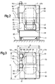
- the device for coating tablets shown in FIGS. 1 to 4 has a frame 3 standing on the floor 1 of a room, which is formed at least in part from welded profile bars.
- a drum 7 is rotatably mounted about a horizontal axis of rotation 5.
- this is provided with a perforation formed by holes 7b, namely bores, the holes 7b being drawn in an exaggerated size for clarity.
- the perforation holes 7b are evenly distributed over the circumference of the cylindrical part 7a.
- the perforation does not extend over the entire dimension of the circular cylindrical jacket part 7a measured parallel to the axis of rotation 5, so that it still has an unperforated annular surface on both sides of the perforation.
- the circular cylindrical shell part 7a is adjoined on both sides by a conically tapering, non-perforated wall part 7c or 7d.
- a small cylindrical edge 7e and 7f adjoins the thinner ends of the conical drum-wall parts 7c and 7d.
- a ring 9 projecting radially outward therefrom is rigidly attached, namely welded on.
- this is additionally connected to the wall part 7c by a cylindrical ring 11, the ring 11 also being fastened by welded connections.
- the jacket part 7a is provided with a removal opening 7g for removing the tablets.
- This opening 7g extends over the entire dimension of the jacket part 7a measured parallel to the axis of rotation 5 into the wall parts 7c, 7d and can be closed with a closure element 13 which is hinged 15 about a axis parallel to the axis of rotation 5 Swivel axis is pivotally connected to the drum.
- the closure element 13 is, for example, also perforated and its outer surface merges smoothly and continuously into the outer surface of the remaining shell part 7a in the closed position, apart from the hinges located at the edges of the shell part 7a. How else is explained in more detail, the closure element 13 can be held or opened in the closed position either by means of at least one pneumatic adjusting member 17 mounted on the drum. In the interior of the drum 7, there can also be attached blades (not shown) for taking the tablets.
- the frame 3 has, among other things, a yoke 3a located on the left in FIG. 4, the uppermost part of which forms a vertically arranged, square frame.
- a ring 19 is rigidly attached to this, namely welded on.
- a ring 25a of a bearing 25 is detachably and rigidly fastened by means of screws 23, a spacer ring 21 being arranged between the ring 19 and the bearing ring 25a.
- the ring 25b of the bearing 25 which is rotatable with respect to the ring 25a can be detached with screws 27 and is rigidly fastened to the ring 9.
- Rolling elements are arranged between the two bearing rings.
- the bearing 25 is thus designed as a roller bearing, for example a ball bearing, and is used both for the radial and for the axial bearing of the drum 7.
- the latter is exclusively due to the bearing located on one side of the cylindrical, perforated jacket part 7a at its one end face 25 stored.
- the two bearing rings 25a, 25b on both sides of the rolling elements i.e. Balls sealed against each other by a lip seal, not shown, so that no lubricant can escape from the bearing.
- a toothed ring 31 with teeth 31a is rigidly and detachably fastened by means of screws 29.
- a drive device 33 having a pneumatic or electric motor and a transmission is attached to the frame 1, on one side a through the drum axis of rotation 5 vertical plane approximately at the level of the deepest part of the drum wall.
- the drive device 33 has a toothed wheel 35 which is operatively connected to the toothed ring 31 via a toothed belt 37, which has been omitted in FIG.
- the rings connected to one another by the screws 23, 27 and 29 can each be connected to one another in a rotationally fixed manner in addition to the screws by means of properly fitting pins.
- the device has a housing which is fastened to the frame 3 and is designated as a whole by 41 and which is formed from a base 41a arranged somewhat below the drum 7 and the drive device 33, two end walls 41b, 41c and a U-shaped wall part 41d, which forms two side walls and a curved top wall that merges into this.
- the housing 41 closes the drum 5 located therein dust-tight and at least to some extent and preferably completely gas-tight from the environment.
- the bottom 41a for example, slopes slightly away from both sides from a center line running parallel to the axis of rotation 5.
- an essentially circular cylindrical connecting piece 43 and 45 is fastened to these or directly to the frame 3, coaxial with the axis of rotation 5.
- the nozzle 43 is slightly thinner than the opening delimited by the inner surface of the drum edge 7e and protrudes a little into it with a little play.
- the nozzle 45 has approximately the same diameter as the drum edge 7f and abuts approximately on it.
- the housing 41 has two intermediate walls 47 and 49 which run at right angles to the axis of rotation 5 and which are located in the region of the ring 11 or the abutment point between the drum edge 7f and the connecting piece 45 the. A large part of the drum 7 and in particular its perforated jacket part 7a is thus in a chamber of the housing interior delimited by the two intermediate walls 47, 49.
- the two intermediate walls 47, 49 are provided with openings for the connecting pieces 43 and 45, wherein rings enclosing these openings of the connecting piece 43 or the abovementioned butting point are fastened to them.
- rings are also still attached, which overlap the rings fastened to the intermediate walls 47, 49 from the central part of the drum 7, together with these form a labyrinth seal and which in the intermediate walls 47, 49 seal existing openings splashproof.
- the drive device 33 is sealed liquid-tight against the chamber of the housing interior between the intermediate walls 47, 49, partly by means of a partition, not particularly shown.
- a nozzle holder tube 51 to which a number of spray nozzles 53 are attached for spraying the coating material, projects through the nozzle 45 into the drum 7.
- the part of the tube 51 protruding from the housing 41 at the end wall 41c is bent upwards and connected to a likewise bent tube 55, which forms part of a telescopic extension guided in guides 57 above the drum 7 parallel to the axis of rotation 5.
- the latter is provided on the end wall 41b with a flange connection for connecting a feed line for the material to be sprayed and, moreover, is extendable in such a way that the nozzle holder tube 51 can be completely pulled out of the drum 7 and the nozzle 45 for cleaning and revision work.
- the end wall 41b is provided with an opening which has a closure element 59 which is pivoted by a and lockable door or possibly a releasably attached plate is formed, at least reasonably gas-tight lockable.
- the closure element 59 in particular also lies somewhat close to the connector 43.
- the end wall 41c is provided in the area of the connecting piece 45 with an opening which can be closed by a closure element 63 which is formed by two lockable door leaves 65, 67.
- the two door leaves 65, 67 overlap one another in the closed position in the region of the eccentrically arranged nozzle holder tube 51 and are each provided with a sealed recess penetrated by it.
- the edge 7e of the drum wall delimits a circular, central opening 71, ie, coaxial with the axis of rotation 5, on the bearing-side drum end face together with the nozzle 43 projecting into it. Furthermore, the edge 7f of the drum wall together with the approximately with it aligned nozzle 45 on the end of the drum facing away from the ball bearing 25 an opening 73 coaxial to the axis of rotation 5.
- the clear widths, ie the diameters of the openings 71, 73 are at least 25% and preferably at least 40% of the maximum outside diameter of the drum 7, ie the outside diameter of the jacket part 7a. Furthermore, the clear widths or diameters of the openings 71, 73 are at least 300 mm and expediently at least 450 mm.
- the outside diameter of the drum 7 can be, for example, 1250 mm gene and the diameter of the openings 71, 73 can then be in the size of 600 mm.
- end wall 41c There are other openings on the end wall 41c, which can be closed tightly by cover plates 81, 83, 85 releasably fastened with screws or snap elements. Furthermore, a switching panel 87 with various display instruments and operating elements is arranged on the end wall 41c.
- the ridge of the housing 41 is formed by a metal bar 89.
- Hinged covers 91, 93 are fastened to this by means of hinges on both sides of the vertical plane running through the axis of rotation 5. From a closed position shown in FIGS. 2 and 3, in which they are locked and close openings in wall part 41d, these can be folded up into the open position shown in FIG. 1 and supported with supports.
- the wall part 41d is provided below the hinged cover 93 with another opening, which is closed by a releasably attached cover plate 95.
- An opening 41e is also present in the bottom 41a of the housing 41. This can be closed with a closure element 107 shown in FIG. 4 in the closed position, the design of which will be explained in more detail.
- the frame 3 is designed in such a way that a space remains between the floor 1 and the housing floor 41a into which a carriage 97 can be inserted, which has a handle, a bowl-shaped or trough-shaped container 99 which is open at the top and one with the latter connected, lockable outlet 101.
- nozzles for spraying water or another cleaning liquid arranges, one of which is shown in Figure 4 and designated 103. Furthermore, at least one nozzle 105 for spraying the cleaning liquid is also arranged inside the drum 7 on the nozzle holder tube 51.
- the nozzles 103, 105 are connected via lines, not shown, to a cleaning liquid source having a pump.
- a fan 111 for supplying air is connected via a filter 113, a heating element 115 and a line 117, into which a shut-off element 119 is connected, to the connection 121 of a line 123, which passes through the housing 41 from the top side thereof opens into the nozzle 45.
- An air or gas transmission shoe 131 is arranged in the interior of the housing 41, specifically with respect to the axis of rotation 5 in the lower quadrant which is located in FIG. 1 on the left side of the vertical plane running through the axis of rotation 5.
- the transfer shoe 131 as will be explained in more detail, is displaceably guided at right angles to the axis of rotation 5.
- the transfer shoe 131 can be manually shifted from its operating position shown in FIGS.
- the width of the transfer shoe 131 measured parallel to the axis of rotation 5 is at least equal to the corresponding extent of the perforated section of the jacket part 7a, but the transfer shoe is dimensioned such that the hinges 15 can pass through it on both sides when the drum 7 is rotated.
- the two ring-shaped coupling pieces 135, 137 abut one another at a contact plane which runs vertically and also forms a certain angle with the direction of displacement of the transfer shoe, which is expediently at most 45 °.
- the plane of contact is such that the coupling pieces 135, 137 can be separated by a displacement of the transfer shoe 131 directed away from the drum.
- At least one of the two coupling pieces 135, 137 is expediently provided with an elastically deformable sealing ring.
- releasable clamping means can be provided around the two coupling pieces 135, 137 overlap in the operating position and pull against each other.
- the tensioning means would be designed in such a way that they can be moved from a tensioned position, in which they pull the coupling pieces 135, 137 against one another, into a release position, in which the coupling pieces by moving the transfer shoe, in a few simple steps, for example by pivoting a lever are separable from each other.
- the connection 143 is connected to a suction blower 151 via a line 145, into which a shut-off device 147 is switched on, and a filter 149.
- the lines 117 and 145 are connected to one another by the shut-off elements 119 and 147, cross-bridging lines 153, 157, in each of which a shut-off element 155 and 159 is also switched on.
- the shut-off devices 119, 147, 155, 159 have a passage which can be shut off by a so-called ventilation flap.
- blowers 111, 151, the filters 113, 149, the heating element 115 and the shut-off elements 119, 147, 155, 159 do not have to be arranged above the housing 41, contrary to the only schematic illustration in FIG. 1, but can be arranged anywhere, but preferably outside the housing 41. It should also be noted that the lines 153 and 157 together with the shut-off devices 155, 159 can be omitted, with the result that the shut-off devices 119 and 147 connected in the lines 117 and 145 also become unnecessary.
- a guide 171 is arranged, for example in the manner of a Drawer extension is formed and has rails attached to the housing 41 or directly to the frame 3, which run at right angles to the axis of rotation of the drum and are either arranged horizontally or are inclined slightly downwards or upwards with respect to a horizontal plane.
- a slide is slidably guided on these rails with rollers or sliding surfaces, which in turn has races on which the transfer shoe 131 is in turn slidably guided with rollers or sliding surfaces.
- the latter is provided with handles 173 which, when the hinged cover 91 is opened, can be gripped from the outside through the opening 175 in the housing 41.
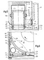
- the transfer shoe 131 can be shifted from its operating position shown in FIGS. 1, 3 and also 5 and 6 away from the drum to a stop in its other, also already mentioned cleaning end position in the manner already mentioned.
- the displacement distance between the two end positions is at least 30 cm and, for example, approximately 50 cm, so that there is a correspondingly large gap in the cleaning end position between the drum 7 and the transfer shoe.
- the transfer shoe 131 can also be lifted off the carriage and completely separated from the rest of the work.
- the transmission shoe 131 is essentially designed as a hollow box, the side of which, in the operating position, facing the jacket part 7a of the drum 7 has a shape which is coaxial with the axis of rotation of the drum.
- the transmission shoe 131 is open in the region of its side facing the drum, or, in other words, has an orifice opening on this side that communicates with its cavity.
- This mouth opening is delimited on two sides facing away from each other by a seal 181 which forms a circular arc coaxial with the axis of rotation of the drum. In the operating position, each of the two seals 181 bears against one of the hole-free edge sections of the jacket part 7a.
- an arcuate plate 185 is inserted, which is coaxial with the drum axis of rotation. At its upper edge and at its two side edges, this is connected in a gas-tight manner to the wall of the transfer shoe.
- three seal holders 187, 189, 191 are fastened. These are offset from one another on a circular arc running around the drum axis of rotation 5 and, moreover, have approximately the shape of U-shaped channels which are open towards the drum.
- a seal 193 can optionally be inserted into one of these seal holders, for example, as shown in FIG.
- closure elements 13 and 107 The formation of the closure elements 13 and 107 and their actuating means will now be explained in more detail with reference to FIGS. 7 and 8.
- the two hinges 15 are arranged on different sides of the perforation of the casing part 7a outside of this perforation and are fastened, for example, to the two hole-free edge strips of the casing part 7a, the hinge pivot axis being on the outside of the wall part 7a.
- the closure element 13 is supported at both ends by an angle lever 201 on the hinges.
- the pneumatic adjusting element 17 has a cylinder 199, which is articulated at one end with a joint 203 on the conical wall part 7d of the drum 7, the pivot axis of the joint 203 extending parallel to the drum axis of rotation 5 in the same way as that of the hinges 15.
- a piston 205 is guided in the cylinder 199, the shaft of which is connected via a crank arm 207 to the bolt of the relevant hinge 15, which in turn is connected to the angle lever 201 in a rotationally fixed manner.
- the cylinder 199 also contains a compression spring acting on the piston 205, which, when the cylinder is without compressed air, presses the piston against the end position in which it holds the closure element 13 in its closed position shown in FIGS. 4 and 7. If necessary, a seal can be provided that seals the closure element 13 in the closed position against the jacket part 7a.
- a compressed air line 209 is connected to the compressed air connection of the cylinder 199, the main part of which runs along the outside of the wall part 7d and the end facing away from the pneumatic cylinder is guided at the edge 7f on the inside thereof and has a compressed air coupling piece 211 .
- a stationary compressed air source not shown, is connected to another compressed air coupling piece via at least one valve, which is arranged in the switching panel 87 or can be actuated from it, and a compressed air line held at least in part on the frame 3 or housing 41.
- One of the two coupling pieces can be detached manually from the holder or at least adjustable, so that the two coupling pieces can be detachably connected to one another when the drum 7 is in the rotational position shown in FIGS. 4, 7 and 8 and the door leaves 65, 67 are open .
- the cylinder 199 of the adjusting member 17 can be pressurized with compressed air by actuating a valve, as a result of which the closure element 13 is pivoted downward from its closed position into its release position shown in FIG. 8 and remains in the cylinder until it is vented.
- the closure element 13 can therefore only be opened if the two compressed air coupling pieces are connected to one another. Otherwise, the electrical-pneumatic control device of the device Expediently on switching means which ensure that the drive device 33 of the drum can only be put into operation when the closure element 13 is in its closed position and the compressed air coupling pieces mentioned are separated from one another.
- switching means can have, for example, a limit switch which is built into the coupling piece which can be connected to the coupling piece 211 and which changes its switching state when the two coupling pieces are connected and controls an electrical contactor or a valve, so that the supply of the electric or pneumatic motor of the drive device 33 is interrupted.
- the removal opening 7g and the closure element 13 are located approximately at the lowest point of the drum 7, or more precisely, the casing part 7a.
- the removal opening 7g in the removal rotary position, as drawn in FIGS. 7 and 8, can be symmetrical to a vertical plane through the axis of rotation of the drum.
- the removal opening should not protrude into the area of the gas transmission shoe 131 and can therefore, depending on the extent of the latter and its own extent in the removal rotation position, be arranged somewhat asymmetrically to the vertical plane mentioned and against the lower drum facing away from the transmission shoe 131 - Quadrants are offset.
- the removal opening 7g should expediently be in the removal rotation position however, form or include the lowest point of the jacket part 7a.
- the opening 41e of the housing bottom 41a is at least partially below the removal opening 7g of the drum 7.
- the opening 41e expediently has larger dimensions in plan than the removal opening 7g, so that the latter in the floor plan, ie in a vertical projection, encompassed on all sides.
- the closure element 107 used to close the opening 41g of the base 41a can be designed, for example, as a flap which is pivotally mounted with hinges 221 about a pivot axis parallel to the axis of rotation 5 of the drum.
- there is at least one pneumatic adjusting element 223 which has a cylinder arranged on the lower side of the base 41a and a piston which is connected to the closure element 107 via an articulated connection.
- the bottom 41a or possibly the closure element 107 is expediently provided with a seal, so that the opening 41e is closed in a fluid-tight manner when the closure element 107 is in its closed position shown in FIGS. 4, 6 and 7.
- the closure element 107 is pivoted downward into its release position shown in FIG. 8. If the closure element 13 is also in its release position, it may possibly protrude partially through the opening 41g.
- a batch of tablets to be coated is introduced into the drum 7 through one of the openings 71 or 73. Then the opening in question again closed and the drum 7 rotated by means of the drive device 33 in the direction of the arrow 195 shown in FIG.
- the tablet batch is moved by the rotary movement of the drum 7 in the quadrant of the drum 7 in which the transfer shoe 131 is arranged.
- the tablet batch or layer can then be delimited, for example, by the delimitation surface 197 shown in broken lines in FIG. 6.
- liquid or coating material formed by a suspension is fed through the tubes 55 and 51 and sprayed onto the tablets with the spray nozzles 53.
- filtered and heated air or possibly a protective gas is blown into the drum 7 by the fan 111 via the filter 113, the heating element 115 and the line 123.
- the air or the protective gas is sucked through the tablet charge and the holes 7b located in the area of the mouth of the transfer shoe 131 into the transfer shoe 131 and flows from the latter via the line 141 via the filter 149 to the suction fan 151.
- the drum 7 When the coating has been applied to the tablets, the drum 7 is stopped in the emptying or removal rotating position. The closure elements 13 and 107 can then be opened, so that the tablets slide out of the drum 7 through the two openings 7g and 41e into the container 99 of the carriage 97 and fall and can be transported further therewith.
- the tablets present in the drum come out of the drum at least to a large extent solely as a result of the force of gravity acting on them. If some of the tablets remain in the drum should, for example, an operator can push the remaining tablets from one of the drum end faces with a suitable tool to the removal opening. The tablets can be removed quickly and easily.
- the two fans 111 and 151 can be dimensioned and possibly regulated or controlled in such a way that there is approximately ambient pressure in the drum 7 during the coating process. This makes it possible to temporarily open one of the two closure elements 59 or 63 during the covering process for a visual inspection without any significant amounts of air flowing into the drum or air and sprayed coating material out of the latter.
- the adjustability of the seal 193 makes it possible to adapt the circumferential or angular range of the drum, via which air is sucked out of the drum 7 into the transfer shoe 131, to the quantity and mobility of the tablets placed in the drum 7. In this way it can be achieved that the suction area, i.e. the effective mouth opening of the transfer shoe 131 extends approximately over the entire tablet batch, but not beyond this.
- the drum 7, the spray nozzles 53, the transfer shoe 131 and other parts of the device must be used from time to time and especially when changing the product, i.e. the tablets and / or the coating material. Cleaning is facilitated by the nozzles 103, 105, with which the drum 7 can be sprayed inside and outside with water or another cleaning liquid.
- the latter can be drained or pumped off, for example, when the closure element 13 is closed, via an outlet provided at the lowest point of the housing base 41a, it possibly being possible to provide a closed circuit.
- the closure element 107 present in the bottom 41a can also be opened and the cleaning liquid can be discharged into the container 99 of the trolley 97 or into another container.
- the mere spraying and spraying of the drum 7 and the interior of the housing is not sufficient to achieve sufficient cleanliness.
- the closure elements 59 and 63 which are preferably designed as doors
- the interior of the drum can be made accessible from both ends of the drum, so that the inside surface of the drum can be scrubbed, for example, with a brush.
- the nozzle holder tube 51 can be temporarily pulled out of the drum.
- the partially curved hinged covers 91 and 93 can be opened.
- the jacket part 7a is accessible from both sides and from above, which also makes it possible to scrub the outer surfaces of the drum.
- the hinged lid 91 is open, the transfer shoe 131 can also be moved into the cleaning end position.
- While the transmission shoe 131 is in its operating position completely within the housing 41, it is in its cleaning end position at least partially and preferably completely outside the housing 41. Furthermore, if necessary, it can be lifted off the slide of the drawer pull-out guide 171 and completely separated from the frame 3 and the housing 41. So when the transfer shoe 131 is pushed back from its cleaning end position into its operating position, the two coupling pieces 135, 137 automatically come back into the position in which they connect the transfer shoe 131 gas-wise to the line piece 139, which is mechanically rigid with the frame 3 is connected.
- the parts to be cleaned can thus be made quickly and easily accessible by opening or removing the closure elements 59, 63 and the hinged covers 91, 93, wherein the transfer shoe 131 can also be quickly and easily separated from the drum 7. After cleaning, the transfer shoe 131 can be brought back into its operating position and the hinged covers 91, 93 as well as the closure elements 59, 63 can be closed and locked with existing holder means or otherwise secured in their closed positions.
- the bearing 25 and the toothed ring 31 are located in a spatial area whose greatest distance from the adjacent edge of the cylindrical shell part 7a along the axis of rotation 5 measured at most about 40% and for example about or at most 30% of the largest outside diameter of the drum, ie of the outer diameter of the jacket part 7a.
- This contributes to the floor plan dimensions of the main parts of the device, namely the frame 3, the drum 7, the bearing 25 of the drive and transmission means 31, 33, 35, 37, the housing 41 and the in the Transfer shoe 131 in the operating position to keep relatively small compared to the drum dimensions, which is advantageous in terms of accessibility and also in terms of the space requirement of the device.
- the floor plan dimensions of the main parts mentioned ie practically the entire device with the exception of the blower 111, 151, the filter 113, 149, the heating element 115 and the shut-off elements 119, 147, 155, 159, which are not absolutely necessary, are therefore only comparatively little larger as the plan dimensions of the drum 7.
- the plan dimension of the mentioned main parts measured transversely to the drum axis of rotation 5 is at most 1.5 times, namely approximately 1.3 times the outer diameter of the drum 7 or more precisely , the thickest part of the drum.
- the floor plan dimension b of said main part measured parallel to the axis of rotation 5 of the frame and housing is furthermore at most twice and preferably at most 1.8 times the drum dimension measured in the same direction.
- the relationship between the housing-frame-floor plan dimension measured parallel to the axis of rotation can be and the drum dimension measured in the same direction can be made equal to or less than 1.6 and even approximately equal to or less than 1.5.
- the switching panel 87 can possibly also be arranged separately from the rest of the device.
- the device can be modified in various ways.
- the bottom of the housing surrounding the drum can be designed as a trough.
- an opening 341e which corresponds to the opening 4le.
- guides 343 attached to the bottom 341 or to the frame of the device, a closure element 307 is guided horizontally and, for example, displaceably parallel to the axis of rotation of the drum.
- the closure element 307 can be moved from its closed position shown in FIG. 9, in which it closes the opening 341e, into a release position, in which it releases it.
- the closure element 307 corresponding to the purpose of the closure element 107, can be displaced, for example, with a pneumatic adjusting element, which has a cylinder attached to the underside of the base 341 and a piston connected to the closure element 307.
- the cylinder can, for example, contain a return spring which acts on the piston and which holds the closure element 307 in the closed position when the cylinder is depressurized.
- the bottom 341 is provided with means which delimit a downwardly open channel or groove which runs along the edge of the opening 341e.
- a seal 345 which completely surrounds the opening 341e is inserted in this.
- This has a generally rectangular profile and a cavity 345a and is elastically deformable, in particular stretchable in cross section.
- the cavity 345a is sealed off from the environment and fluidly connected by a line 347 to a schematically indicated compressed air control device 349. This has means to inflate the seal after the closing of the closure element 307 with compressed air and to vent it before or when opening the closure element 307.
- closure element 307 When the closure element 307 is in its closed position and the seal 345 is inflated, the lips or ribs present on the lower side of the latter are pressed against the closure element and result in a fluid-tight seal of the opening 341e. If the closure element 307 is moved with the seal 345 vented, the closure element can be displaced relatively easily.
- closure element 107 shown in FIGS. 4, 6, 7 and 8 could be sealed in a similar manner in the closed position with an inflatable and deflatable seal.
- inflatable and ventable seals can also be provided for sealing the closure elements 59, 63 and the hinged covers 91, 93 and possibly also the cover plates 81, 83, 85.
- the drum could also be driven via a gear with sprockets and a chain or via a gear with directly meshing gears.
- the bearing used to support the drum and the toothed ring rigidly connected to the drum should, however, be designed and arranged in such a way that - in a projection parallel to the axis of rotation of the drum - they are either outside the limiting means which are located on the relevant drum. Limit the central opening that is present on the end face, or at most form at least part of these limiting means.
- closure element 13 is also perforated, the perforation of the wall part 7a extends practically without interruption along the entire circumference of the drum. That to close. the removal
- closure element serving to open the drum could also be hole-free instead of perforated. The perforation of the drum would then still be uninterrupted along the circumference of the drum, apart from the interruption by the relatively narrow closure element.
- each seal holder of the transfer shoe 187, 189, 191 In order to determine the extent of the mouth opening of the transition shoe 131, one can then either use seals in all holders 187, 189, 191 or not, the bottom seal determining the extent of the mouth opening. Furthermore, a different number of holders could also be provided instead of the three holders 187, 189, 191. Furthermore, the seal 193, which can be used in different positions, could be replaced by a seal which is displaceably guided along a circular arc coaxial with the axis of rotation of the drum and which can be continuously adjusted with adjusting means. It would also be possible to make the transmission shoe changeable by delimiting the mouth opening.
- the drawer-like guide for the transfer shoe could be replaced by a simple sliding guide.
- the frame could then be provided with a support that can carry and position the transfer shoe in the operating position.
- a manually operable locking device can be provided so that the transfer shoe can be quickly dismantled for cleaning and then re-installed.
- the rear wall of the transfer shoe facing away from the drum could also be at least at least one opening must be provided, which can be optionally locked and released with a closure element, for example a door.
- the transfer shoe If the transfer shoe is used to pass air, the door would of course be closed, whereas it could be opened for cleaning. If the transfer shoe is provided with such a closable opening, it therefore no longer needs to be removed for cleaning and can then even be attached non-detachably.
- other muscular force-operated adjusting elements for example hydraulic or electrical adjusting elements, could also be provided.
Landscapes
- Chemical & Material Sciences (AREA)
- Organic Chemistry (AREA)
- Chemical Kinetics & Catalysis (AREA)
- Life Sciences & Earth Sciences (AREA)
- Health & Medical Sciences (AREA)
- Polymers & Plastics (AREA)
- Food Science & Technology (AREA)
- Engineering & Computer Science (AREA)
- Medicinal Chemistry (AREA)
- Pharmacology & Pharmacy (AREA)
- Animal Behavior & Ethology (AREA)
- General Health & Medical Sciences (AREA)
- Public Health (AREA)
- Veterinary Medicine (AREA)
- Medical Preparation Storing Or Oral Administration Devices (AREA)
Applications Claiming Priority (4)
| Application Number | Priority Date | Filing Date | Title |
|---|---|---|---|
| CH3346/81 | 1981-05-22 | ||
| CH334781A CH659593A5 (en) | 1981-05-22 | 1981-05-22 | Device for coating tablets |
| CH334681 | 1981-05-22 | ||
| CH3347/81 | 1981-05-22 |
Related Parent Applications (1)
| Application Number | Title | Priority Date | Filing Date |
|---|---|---|---|
| EP82901494.3 Division | 1982-12-02 |
Publications (3)
| Publication Number | Publication Date |
|---|---|
| EP0137151A2 true EP0137151A2 (fr) | 1985-04-17 |
| EP0137151A3 EP0137151A3 (en) | 1985-07-10 |
| EP0137151B1 EP0137151B1 (fr) | 1987-08-26 |
Family
ID=25692796
Family Applications (3)
| Application Number | Title | Priority Date | Filing Date |
|---|---|---|---|
| EP84108341A Expired EP0137150B1 (fr) | 1981-05-22 | 1982-05-21 | Dispositif pour recouvrir des particules, notamment des médicaments sous forme de particules telles que des comprimés |
| EP84108342A Expired EP0137151B1 (fr) | 1981-05-22 | 1982-05-21 | Dispositif pour recouvrir des particules, notamment des médicaments sous forme de particules telles que des comprimés |
| EP82901494A Expired EP0079348B1 (fr) | 1981-05-22 | 1982-05-21 | Dispositif pour recouvrir des particules, notamment des medicaments sous forme de particules telles que des tablettes |
Family Applications Before (1)
| Application Number | Title | Priority Date | Filing Date |
|---|---|---|---|
| EP84108341A Expired EP0137150B1 (fr) | 1981-05-22 | 1982-05-21 | Dispositif pour recouvrir des particules, notamment des médicaments sous forme de particules telles que des comprimés |
Family Applications After (1)
| Application Number | Title | Priority Date | Filing Date |
|---|---|---|---|
| EP82901494A Expired EP0079348B1 (fr) | 1981-05-22 | 1982-05-21 | Dispositif pour recouvrir des particules, notamment des medicaments sous forme de particules telles que des tablettes |
Country Status (4)
| Country | Link |
|---|---|
| US (1) | US4543906A (fr) |
| EP (3) | EP0137150B1 (fr) |
| DE (1) | DE3276898D1 (fr) |
| WO (1) | WO1982003972A1 (fr) |
Cited By (2)
| Publication number | Priority date | Publication date | Assignee | Title |
|---|---|---|---|---|
| WO1991012789A1 (fr) * | 1990-02-20 | 1991-09-05 | Gebrüder Lödige Maschinenbau GmbH | Dispositif d'enduction avec une pellicule et/ou avec du sucre |
| EP0891808A1 (fr) * | 1997-07-17 | 1999-01-20 | Glatt Maschinen- und Apparatebau AG | Tambour pour recevoir un produit en particule, dispositif contenant un tambour et procédé pour la fabrication du tambour |
Families Citing this family (22)
| Publication number | Priority date | Publication date | Assignee | Title |
|---|---|---|---|---|
| EP0137150B1 (fr) * | 1981-05-22 | 1987-08-26 | Glatt Maschinen- und Apparatebau AG | Dispositif pour recouvrir des particules, notamment des médicaments sous forme de particules telles que des comprimés |
| CH656077A5 (de) * | 1982-01-29 | 1986-06-13 | Glatt Maschinen & Apparatebau | Verfahren zum ueberziehen von teilchen, insbesondere arzneimittel-teilchen, und vorrichtung zur durchfuehrung des verfahrens. |
| DE3310232A1 (de) * | 1983-03-22 | 1984-09-27 | Driam Metallprodukt Gmbh & Co Kg, 7991 Eriskirch | Verfahren und vorrichtung zum aufbringen einer vielschichtigen umhuellung auf granulate wie drageekerne |
| US4639383A (en) * | 1983-09-20 | 1987-01-27 | Thomas Engineering, Inc. | Method and apparatus for coating particulate granules |
| CH664005A5 (de) * | 1984-05-19 | 1988-01-29 | Glatt Maschinen & Apparatebau | Verfahren zum trocknen eines teilchenfoermigen gutes und einrichtung zur durchfuehrung des verfahrens. |
| FR2603154B1 (fr) * | 1986-09-02 | 1989-06-30 | Ceres | Procede de pelliculage des semences |
| US4724019A (en) * | 1987-03-20 | 1988-02-09 | Warner-Lambert Company | Method and apparatus for sealing capsules |
| US4844001A (en) * | 1987-12-30 | 1989-07-04 | Mcneil Lab, Inc. | Removable and rotatable coating pan spray arm assembly |
| JPH0356697A (ja) * | 1989-07-21 | 1991-03-12 | Takashi Kobayashi | 自動開閉バレル |
| DE4005208C2 (de) * | 1990-02-20 | 1995-07-06 | Loedige Maschbau Gmbh Geb | Vorrichtung mit einer um eine Achse rotierenden Trommel für Überzugsgut, insbesondere für die Filmlackierung und/oder Zuckerdragierung |
| CH686858A5 (it) * | 1991-10-31 | 1996-07-31 | Soremartec Sa | Bassina, particolarmente per il rivestimento di prodotti dolciari, prodotti farmaceutici e simili. |
| JP3096725B2 (ja) * | 1991-12-04 | 2000-10-10 | 東和工機株式会社 | バレル入り物品の表面処理設備における処理済み物品排出装置 |
| US5441565A (en) * | 1992-12-15 | 1995-08-15 | Mcneil-Ppc, Inc. | System for coating pharmaceutical products |
| US5443637A (en) * | 1993-09-17 | 1995-08-22 | Coating Machinery Systems, Inc. | Means for continuously coating particulate material |
| US6142095A (en) * | 1998-06-03 | 2000-11-07 | Coating Machinery Systems, Inc. | Machine for coating particulate material |
| IT1311094B1 (it) * | 1999-10-15 | 2002-02-28 | Gs Coating System Srl | Macchina per il rivestimento di articoli granulari e simili. |
| FR2804889B1 (fr) * | 2000-02-16 | 2002-10-25 | F Dumoulin Et Cie Ets | Dispositif de nettoyage de distribution ou de dosage pour installation de drageification ou d'enrobage de produits |
| US6511541B2 (en) | 2001-02-27 | 2003-01-28 | Spray Dynamics, Ltd. | Powder applicator for particulate material coating |
| JP4522773B2 (ja) * | 2004-07-20 | 2010-08-11 | 株式会社パウレック | コーティング装置 |
| JP5324881B2 (ja) * | 2008-10-21 | 2013-10-23 | フロイント産業株式会社 | パンコーティング装置 |
| US9266142B2 (en) | 2011-09-06 | 2016-02-23 | Kabushiki Kaisha Powrex | Coating device |
| DE102012011286A1 (de) * | 2012-06-08 | 2013-12-12 | Glatt Maschinen- Und Apparatebau Ag | Vorrichtung zum Beschichten oder Umhüllen von Partikeln |
Family Cites Families (26)
| Publication number | Priority date | Publication date | Assignee | Title |
|---|---|---|---|---|
| DE232744C (fr) * | ||||
| US1122660A (en) * | 1914-04-20 | 1914-12-29 | Sturtevant Mill Co | Mixing-machine. |
| US2710574A (en) * | 1951-02-03 | 1955-06-14 | Harleston E Runion | Eliminating ink mist or other detritus from rooms |
| US2944512A (en) * | 1956-07-17 | 1960-07-12 | Martin Co | Method and apparatus for spray painting small articles |
| BE636475A (fr) * | 1962-09-28 | |||
| US3229609A (en) * | 1964-01-15 | 1966-01-18 | Nat Ind Equipment Co | Multiple air screen for use with a doorway |
| DE1225035B (de) * | 1964-03-07 | 1966-09-15 | Pietro Pellegrini | Maschine zum Kandieren von Zuckerwaren, Bonbons u. dgl. |
| BE755890A (nl) * | 1969-09-10 | 1971-02-15 | Pielkenrood Vinitex Bv | Samenstel voor het van een ruimte afscheiden van een althans nagenoeg stofvrij gedeelte |
| US3696778A (en) * | 1969-11-17 | 1972-10-10 | George A Moore | Breading machine |
| US3573966A (en) * | 1970-01-15 | 1971-04-06 | Lilly Co Eli | Tablet coating method |
| US3601086A (en) * | 1970-08-12 | 1971-08-24 | Lilly Co Eli | Tablet-coating apparatus |
| US3834347A (en) * | 1971-06-16 | 1974-09-10 | Freunt Ind Co Ltd | Tablet coating apparatus |
| US3934545A (en) * | 1971-11-15 | 1976-01-27 | Alpha Sheet Metal Works, Inc. | Apparatus for enrobing discrete objects |
| IT958706B (it) * | 1972-03-16 | 1973-10-30 | Skf Ind Trading & Dev | Cuscinetto volvente di ridotto ingombro assiale atto a sopportare forze radiali e momenti |
| DE2212985A1 (de) * | 1972-03-17 | 1973-09-20 | Manfred Sauter | Drageemaschine |
| DE2245265A1 (de) * | 1972-09-15 | 1974-03-21 | Trox Gmbh Geb | Luftausblasvorrichtung |
| DE2249863A1 (de) * | 1972-10-11 | 1974-04-18 | Werner Glatt | Vorrichtung zum dragieren von pillen, tabletten, granulaten und dergleichen |
| SU489511A1 (ru) * | 1973-01-02 | 1975-10-30 | Ордена Трудового Красного Знамени Институт Тепло-И Массообмена Ан Белорусскойсср | Устройство дл нанесени защитных покрытий на лекарственные формы |
| US3960196A (en) * | 1973-03-14 | 1976-06-01 | Erling Berner | Door closure |
| DE2315882C3 (de) * | 1973-03-30 | 1975-10-23 | Glatt, Werner, 7859 Haltingen | Trocknungsvorrichtung für eine Dragiertrommel |
| US3975995A (en) * | 1975-03-13 | 1976-08-24 | American Air Filter Company, Inc. | Ventilated ceiling construction |
| JPS547747A (en) * | 1977-06-18 | 1979-01-20 | Shigeru Togami | Sliding door device for preventing child finger from being pinched |
| DE2805801A1 (de) * | 1978-02-11 | 1979-08-16 | Driam Metallprodukt Gmbh & Co | Vorrichtung zum beschichten von granulaten wie drageekerne mit einer huelle und zum antrocknen der huelle durch trocknungsluft |
| DE2911462C2 (de) * | 1979-03-23 | 1981-12-03 | Hansa Ventilatoren u. Maschinenbau Neumann GmbH & Co KG, 2915 Saterland | Verfahren und Vorrichtung zur Reinhaltung der Luft in einer Frischwarenabteilung |
| FR2461205A1 (fr) * | 1979-07-09 | 1981-01-30 | Sofrair | Poste de travail a double flux laminaire |
| EP0137150B1 (fr) * | 1981-05-22 | 1987-08-26 | Glatt Maschinen- und Apparatebau AG | Dispositif pour recouvrir des particules, notamment des médicaments sous forme de particules telles que des comprimés |
-
1982
- 1982-05-21 EP EP84108341A patent/EP0137150B1/fr not_active Expired
- 1982-05-21 EP EP84108342A patent/EP0137151B1/fr not_active Expired
- 1982-05-21 US US06/463,882 patent/US4543906A/en not_active Expired - Lifetime
- 1982-05-21 WO PCT/CH1982/000071 patent/WO1982003972A1/fr not_active Ceased
- 1982-05-21 DE DE8282901494T patent/DE3276898D1/de not_active Expired
- 1982-05-21 EP EP82901494A patent/EP0079348B1/fr not_active Expired
Cited By (2)
| Publication number | Priority date | Publication date | Assignee | Title |
|---|---|---|---|---|
| WO1991012789A1 (fr) * | 1990-02-20 | 1991-09-05 | Gebrüder Lödige Maschinenbau GmbH | Dispositif d'enduction avec une pellicule et/ou avec du sucre |
| EP0891808A1 (fr) * | 1997-07-17 | 1999-01-20 | Glatt Maschinen- und Apparatebau AG | Tambour pour recevoir un produit en particule, dispositif contenant un tambour et procédé pour la fabrication du tambour |
Also Published As
| Publication number | Publication date |
|---|---|
| EP0137150A3 (en) | 1985-07-10 |
| EP0079348A1 (fr) | 1983-05-25 |
| EP0079348B1 (fr) | 1987-08-05 |
| DE3276898D1 (en) | 1987-09-10 |
| US4543906A (en) | 1985-10-01 |
| EP0137151A3 (en) | 1985-07-10 |
| EP0137150A2 (fr) | 1985-04-17 |
| EP0137150B1 (fr) | 1987-08-26 |
| WO1982003972A1 (fr) | 1982-11-25 |
| EP0137151B1 (fr) | 1987-08-26 |
Similar Documents
| Publication | Publication Date | Title |
|---|---|---|
| EP0137150B1 (fr) | Dispositif pour recouvrir des particules, notamment des médicaments sous forme de particules telles que des comprimés | |
| EP0085650B1 (fr) | Installation pour l'enrobage de particules,notamment de comprimés pharmaceutiques | |
| DE2918762C2 (de) | Vorrichtung zum Überziehen bzw. Kandieren von körnigem Gut | |
| DE3131808C2 (de) | Vorrichtung zum Beschichten von Granulaten wie Drageekerne mit einer Hülle und zum Austrocknen dieser Hülle | |
| DE1410177B2 (de) | Trommelruettler | |
| EP0238028B1 (fr) | Installation pour granuler, pelletiser, dragéifier et/ou sécher des matières pulvérulentes | |
| DE1648859B2 (de) | Nutsche | |
| DE69905372T2 (de) | Vorrichtung zur herstellung von teigwaren | |
| DE3103593C2 (fr) | ||
| EP0781949B1 (fr) | Dispositif de lit fluidisé | |
| DE2938795C2 (de) | Dragiervorrichtung | |
| EP0672459B1 (fr) | Centrifugeuse filtrante | |
| CH629114A5 (de) | Anlage zur herstellung einer pastoesen batterie-masse und verfahren zum betrieb der anlage. | |
| DE4342471C1 (de) | Filterzentrifuge | |
| DE68902294T2 (de) | Vorrichtung zur beschichlung von pulverigen oder koernigen stoffen. | |
| EP0188717A1 (fr) | Mélangeur | |
| CH659593A5 (en) | Device for coating tablets | |
| DE2212985A1 (de) | Drageemaschine | |
| DE2445102A1 (de) | Dragiervorrichtung | |
| DE1298081B (de) | Austragsvorrichtung fuer ein Nutschfilter | |
| DE102006057117A1 (de) | Pulver- und Partikelverarbeitungsvorrichtung und Prallplatteneinrichtung | |
| DE69005771T2 (de) | Membranpresse. | |
| DE2707921C3 (de) | Verfahren und Vorrichtung zum Entfernen überschüssigen Metalls von tauchmetallisierten Gegenständen | |
| DE632070C (de) | Ununterbrochen arbeitendes Druckfilter fuer Fluessigkeiten | |
| DE3302588A1 (de) | Einrichtung zum ueberziehen von teilchen und verfahren zum ueberziehen von teilchen |
Legal Events
| Date | Code | Title | Description |
|---|---|---|---|
| PUAI | Public reference made under article 153(3) epc to a published international application that has entered the european phase |
Free format text: ORIGINAL CODE: 0009012 |
|
| AC | Divisional application: reference to earlier application |
Ref document number: 79348 Country of ref document: EP |
|
| AK | Designated contracting states |
Designated state(s): AT BE CH DE FR GB LI NL |
|
| PUAL | Search report despatched |
Free format text: ORIGINAL CODE: 0009013 |
|
| AK | Designated contracting states |
Designated state(s): AT BE CH DE FR GB LI NL |
|
| 17P | Request for examination filed |
Effective date: 19850829 |
|
| 17Q | First examination report despatched |
Effective date: 19860415 |
|
| GRAA | (expected) grant |
Free format text: ORIGINAL CODE: 0009210 |
|
| AC | Divisional application: reference to earlier application |
Ref document number: 79348 Country of ref document: EP |
|
| AK | Designated contracting states |
Kind code of ref document: B1 Designated state(s): AT BE CH DE FR GB LI NL |
|
| REF | Corresponds to: |
Ref document number: 29103 Country of ref document: AT Date of ref document: 19870915 Kind code of ref document: T |
|
| ET | Fr: translation filed | ||
| REF | Corresponds to: |
Ref document number: 3277058 Country of ref document: DE Date of ref document: 19871001 |
|
| PLBE | No opposition filed within time limit |
Free format text: ORIGINAL CODE: 0009261 |
|
| STAA | Information on the status of an ep patent application or granted ep patent |
Free format text: STATUS: NO OPPOSITION FILED WITHIN TIME LIMIT |
|
| 26N | No opposition filed | ||
| PGFP | Annual fee paid to national office [announced via postgrant information from national office to epo] |
Ref country code: DE Payment date: 20010419 Year of fee payment: 20 |
|
| PGFP | Annual fee paid to national office [announced via postgrant information from national office to epo] |
Ref country code: AT Payment date: 20010426 Year of fee payment: 20 |
|
| PGFP | Annual fee paid to national office [announced via postgrant information from national office to epo] |
Ref country code: FR Payment date: 20010427 Year of fee payment: 20 |
|
| PGFP | Annual fee paid to national office [announced via postgrant information from national office to epo] |
Ref country code: GB Payment date: 20010503 Year of fee payment: 20 |
|
| PGFP | Annual fee paid to national office [announced via postgrant information from national office to epo] |
Ref country code: CH Payment date: 20010510 Year of fee payment: 20 |
|
| PGFP | Annual fee paid to national office [announced via postgrant information from national office to epo] |
Ref country code: BE Payment date: 20010521 Year of fee payment: 20 |
|
| PGFP | Annual fee paid to national office [announced via postgrant information from national office to epo] |
Ref country code: NL Payment date: 20010528 Year of fee payment: 20 |
|
| BE20 | Be: patent expired |
Free format text: 20020521 *GLATT MASCHINEN- UND APPARATEBAU A.G. |
|
| REG | Reference to a national code |
Ref country code: GB Ref legal event code: IF02 |
|
| PG25 | Lapsed in a contracting state [announced via postgrant information from national office to epo] |
Ref country code: LI Free format text: LAPSE BECAUSE OF EXPIRATION OF PROTECTION Effective date: 20020520 Ref country code: GB Free format text: LAPSE BECAUSE OF EXPIRATION OF PROTECTION Effective date: 20020520 Ref country code: CH Free format text: LAPSE BECAUSE OF EXPIRATION OF PROTECTION Effective date: 20020520 |
|
| PG25 | Lapsed in a contracting state [announced via postgrant information from national office to epo] |
Ref country code: NL Free format text: LAPSE BECAUSE OF EXPIRATION OF PROTECTION Effective date: 20020521 Ref country code: AT Free format text: LAPSE BECAUSE OF EXPIRATION OF PROTECTION Effective date: 20020521 |
|
| REG | Reference to a national code |
Ref country code: GB Ref legal event code: PE20 Effective date: 20020520 |
|
| REG | Reference to a national code |
Ref country code: CH Ref legal event code: PL |
|
| NLV7 | Nl: ceased due to reaching the maximum lifetime of a patent |
Effective date: 20020521 |