EP0137265A2 - Tête de séparation pour pièces de monnaie, destinée à une trieuse-compteuse de pièces de monnaie à grande vitesse - Google Patents
Tête de séparation pour pièces de monnaie, destinée à une trieuse-compteuse de pièces de monnaie à grande vitesse Download PDFInfo
- Publication number
- EP0137265A2 EP0137265A2 EP84110130A EP84110130A EP0137265A2 EP 0137265 A2 EP0137265 A2 EP 0137265A2 EP 84110130 A EP84110130 A EP 84110130A EP 84110130 A EP84110130 A EP 84110130A EP 0137265 A2 EP0137265 A2 EP 0137265A2
- Authority
- EP
- European Patent Office
- Prior art keywords
- coins
- coin
- diameter
- travel
- head
- Prior art date
- Legal status (The legal status is an assumption and is not a legal conclusion. Google has not performed a legal analysis and makes no representation as to the accuracy of the status listed.)
- Withdrawn
Links
Images


Classifications
-
- G—PHYSICS
- G07—CHECKING-DEVICES
- G07D—HANDLING OF COINS OR VALUABLE PAPERS, e.g. TESTING, SORTING BY DENOMINATIONS, COUNTING, DISPENSING, CHANGING OR DEPOSITING
- G07D9/00—Counting coins; Handling of coins not provided for in the other groups of this subclass
- G07D9/008—Feeding coins from bulk
-
- G—PHYSICS
- G07—CHECKING-DEVICES
- G07D—HANDLING OF COINS OR VALUABLE PAPERS, e.g. TESTING, SORTING BY DENOMINATIONS, COUNTING, DISPENSING, CHANGING OR DEPOSITING
- G07D3/00—Sorting a mixed bulk of coins into denominations
- G07D3/12—Sorting coins by means of stepped deflectors
-
- G—PHYSICS
- G07—CHECKING-DEVICES
- G07D—HANDLING OF COINS OR VALUABLE PAPERS, e.g. TESTING, SORTING BY DENOMINATIONS, COUNTING, DISPENSING, CHANGING OR DEPOSITING
- G07D3/00—Sorting a mixed bulk of coins into denominations
- G07D3/16—Sorting a mixed bulk of coins into denominations in combination with coin-counting
Definitions
- This invention relates to coin-sorting and counting apparatus, and more particularly, to coin-queueing heads which align coins for subsequent sorting and counting.
- the centrifugal force is imparted to the coins by the rotation of a disc onto which coins are delivered in bulk, usually through a central hopper.
- the coins are then guided to deliver them to a position adjacent a peripheral retaining rim of the disc.
- the coins are selectively engaged according to denomination by one of a plurality of engagement means such as wheels, blades, cams or the like positioned around the peripheral rim.
- the engagement means depresses or lifts the coins to free them from the peripheral rim of the disc and allows the centrifugal force to hurl them through the air to one of a plurality of corresponding catching devices.
- the coins are then diverted to appropriate collecting bags.
- the sorting is typically accomplished by the engagement means based upon the differences in diameter of the various denominations of coins being processed.
- Conventional engagement means require the coins to be in a single-layer, single-file row at the peripheral rim to avoid malfunctioning of the machine and to insure a proper count.
- the count is usually made by photoelectric means which sense the number of coins entering each catching device.
- the speed at which such machines can sort and count coins is dependent in large part on the ability of the machine to supply coins from the central area of the disc to the peripheral rim. Since the coins are dumped in bulk into the hopper with random orientation, it becomes critical that the coins be properly oriented, arranged in a single layer, and positioned in a single file at the peripheral rim of the disc for engagement by the engagement means. If the process of orienting, arranging and positioning the coins is not accomplished efficiently, the supply of the coins to the engagement means will not be continuous and the operating speed of the machine will be slowed down.
- a vertical stack of two or more of the thinnest coins will not pass under the edge wall and the top coins will be knocked off the stack.
- United States coins currently in circulation a stack of two dimes is approximately equal to the thickness of a half-dollar. As such, it becomes difficult to avoid having a pair of stacked dimes reach the engagement means, and care must be taken to avoid processing a mixture of coins having dimes and half-dollars. The same problems are encountered when processing coinage of other countries.
- edge wall causes other problems even when only processing coins with a thickness less than the height of a double stack of the thinnest coins, such as quarters and Susan B. Anthony dollars United S ates coinage, because coins which are not laying completely flat immediately prior to passing under the edge wall as a result of machine vibration or otherwise, may be engaged by the edge wall. The blocked coin must then be diverted away and recirculated through the machine. This tends to slow up the machine and disrupt its smooth operation, particularly when the edge wall is positioned between the head and the rotating disc along the path of travel of the coins.
- the present invention resides in a coin-queueing head positionable in a spaced relationship over a rotating flexible surface to process randomly oriented coins of varying diameters and place them in a single layer, single file, the head having guide means for guiding the randomly oriented coins to provide a queue of coins including stacked pairs of coins having a first diameter and other ones of the coins having a larger second diameter; engagement means for engaging and blocking passage of one of the stacked pair of coins; and a coin-depressing means positioned in the path of travel of the queue forward of the engagement means for permitting unrestricted travel of the stacked pair of coins to the engagement means and for depressing coins having the second diameter into the flexible surface for travel unrestricted by the engagement means, whereby when the head is operated with the surface rotating the coins are processed into a single layer and a single file ready for sorting by denomination, even when processing coins of the second diameter having a thickness approximating or greater than the height of the stacked Fair of coins.
- the engagement means is an engagement member extending generally transverse to the path of travel of the queue and projecting to a distance above the surface sufficient to engage and block passage of one of the stacked pair of coins.
- the engagement member diverts the blocked coin into a recirculation area for further guiding by the guiding means for reentry into the queue.
- the coin-depressing means is a coin-depressing member positioned to permit unrestricted travel of the stacked pair of coins and to engage coins having the second diameter, the coin-depressing member projecting to a distance above the surface sufficient to depress coins having the second diameter traveling under the coin-depressing member into the flexible surface sufficient to permit their unblocked passage under the engagement member.
- the coin-depressing member is positioned a distance forward of the engagement member, as defined by the path of travel of the queue, sufficient to permit unrestricted travel of the blocked coin between the coin-depressing member and the engagement member, but insufficient for coins of the second diameter to raise from the flexible surface sufficiently to engage and be blocked by the engagement member.
- the distance the coin-depressing member is positioned before the engagement member is greater than the first diameter, but less than the second diameter.
- the coin-depressing member has a ramp cross-section, the ramp sloping toward the path of travel of the queue.
- the coin-queueing head also includes a central opening in the head for receiving said randomly oriented coins; a first peripheral limit extending partialy about the central opening and positioned a first distance from the central opening to define a coin recirculation area and limit outward radial travel of the coins; a first guide extending partially about the central opening generally opposite the first peripheral limit and positioned adjacent to the central opening, the first guide having a portion extending sufficiently around the central opening to define a coin-queueing channel between the portion and a portion of the first peripheral limit coextensive with the first guide portion for receiving coins from the recirculation area, the first guide projecting to a second distance above the surface sufficient to depress any of the coins traveling thereunder into the flexible surface to substantially maintain the radial position of the coins as the surface rotates to deliver said coins back into the recirculation area; and a second peripheral limit extending partially about the central opening and positioned a third distance from the central opening greater than the first distance and radially outward of the first guide, to define
- the engagement member is an engagement wall extending generally transverse to the travel of the coins beyond said coin processing area, the wall extending from the second peripheral limit to the first peripheral limit, and projecting to a fourth distance above the surface sufficient to engage and block passage of one of a pair of stacked coins having a first diameter, the wall being spaced apart from the first guide to define a recirculation passageway therebetween communicating the coin-processing area with the recirculation area, the blocked coin being diverted by the wall back into the recirculation area through the reentry passageway.
- the coin-depressing member is a ramp positioned in the coin-processing area a fifth distance radially inward of the second peripheral limit sufficiently to permit unrestricted travel of tne pair of stacked coins therebetween, the fifth and sixth distances being less than a second, diameter of the coins to be processed having a diameter greater than the first diameter, the ramp projecting to a seventh distance above the surface sufficient to depress any of the coins having the second diameter traveling under the ramp into the flexible surface to permit their unblocked passage under the engagement wall.
- the head also inclues a third peripheral limit extending partially about the central opening and positioned aneighth distance from the central opening, radially outw&rd of the first peripheral limit, to define a coin-sorting channel between the third peripheral limit and a portion of the first peripheral limit coextensive with the third peripheral limit; and a reentry passageway between the first and second peripheral limits for return to the coin-processing area of the coins passing from the coin-sorting channel which remain unsorted.
- the present invention is embodied in a high-speed coin-sorting and counting apparatus, indicated by reference numeral 10. More specifically, the present invention is embodied in an improved coin-queueing head 12 for such an apparatus.
- an undifferentiated mix of coins with random orientation is poured into a loading tray 14 of the apparatus 10 and moves therefrom into a hopper 16 located beneath the tray and immediately above the queueing head 12.
- the queueing head 12 in conjunction with the other parts of the apparatus 10, operates to separate, sort, count and distribute the coins into a plurality of coin bags 18 which are each mounted in one of a plurality of coin-bag-holding receptacles 20, of which there are at least two for each denomination of coin.
- the apparatus when designed to handle United States coinage, the apparatus processes simultaneously pennies, nickels, dimes, quarters, half-dollars, and Susan B. Anthony dollar denomination coins.
- the flow of coins is switched into an adjacent coin bag, and an alarm sounds and an indicator lights up to signal an operator (not shown) to withdraw the receptacle 20 containing the full bag and replace it with another receptacle containing an empty bag.
- Visual indicators positioned on a displ G panel 22 are also provided to show the state of the individual coin bags held by the various receptacles 20.
- the display panel 22 also has visual indicators which show that a particular one of the coin bags 18 needs attention.
- the display panel 22 shows the number of coins of each denomination which has been counted in a particular batch, the value of the counted coins, the subtotal for a particular bag of a batch, and the total for the batch.
- an alpha-numeric printer 24 prints out the information concerning a particular bag, batch or run as desired.
- An electronic memory (not shown) is used to match up the information of present batches with that of other batches for a particular customer.
- Another display panel 26 is provided and is associated with a computer terminal keyboard 28 used to program a specific sorting and counting routine desired for a particular batch of coins.
- the keyboard 28, in addition to being connected to an internal microprocessor may also be connected through a cable to an external computer.
- Flat counter surfaces 30 and 32, located to each side of the loading tray, are provided as work space.
- the apparatus 10 includes a stationary support base 34 which has three upright supports 36, 38 and 40 attached thereto and which supports a rotatable, circular disc 42.
- the queueing head 12 is attached by a hinge 44 to two of the upright supports 36 and 38 and by a flange 46 to the upright support 40 for holding the head in position above an upper surface 48 of the disc 42 by approximately the thickness of the thickest coin to be processed by the apparatus 10.
- the precise vertical position of the head 12 above the upper surface 48 is adjustable through adjustment bolts 50, 52 and 54, which hold the hinge 44 and the flange 46 to the upright supports 36, 38 and 40.
- the hinge 44 permits easy lifting of the head 12 away from the disc 42 for inspection, cleaning and clearing of any obstructions which may occur.
- the bolt 54 includes a thumb-operated cap 55 which may be readily unscrewed to permit the head 12 to be moved about the hinge 44.
- a motor 56 drives the disc 42 through a belt 58 to rotate it in a clockwise direction indicated by arrow 60 when viewed from above.
- the belt 58 rides on a pulley 59 formed as an integral part of the disc 42. The rotation of the disc 42 imparts a centrifugal force to the coins being processed.
- the hopper 16 is rigidly attached to and supported above the queueing head 12, and has a corkscrew interior shape.
- the coins moved into the hopper are funneled into a central circular opening 62 in the head.
- a lower surface or face 64 of the head 12 faces toward the upper surface 48 of the rotating disc 42 and is tapered upwardly from the central opening 62 to its outer perimeter at an angle of approximately four degrees.
- the taper of the lower surface 64 of the head 12 conforms with the taper on the upper surface 48 of the disc 42.
- the taper is provided to facilitate holding coins down on the upper surface 48 of the disc 42, particularly when they reach a peripheral rim 66 of the disc.
- a resilient frictional pad 68 covers the disc 42 and defines the upper surface 48 of the disc.
- the lower surface 64 of the head 12 is a low-friction surface, preferably made of a durable metal surface.
- a conical member 70 is fixedly attached to the disc 42, at its center, below the central opening 62, to prevent coins from remaining in the center of the disk by their avoiding the centrifugal force caused by rotation of the disc. The centrifugal force is necessary to move the coins from the central opening 62 to the peripheral rim 66.
- the disc 42 is rotatably mounted to the base 34 by a shaft 72 supported by a pair of frictionless roller bearings 74.
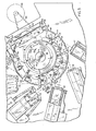
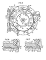
- Fig. 5 the bottom face of the queueing head 12 is shown. It is to be remembered that in the description which follows, based on Fig. 5, the viewer is facing upward and the rotating disc 42 (shown by phantom lines) is spaced toward the viewer by about the thickness of the thickest coin to be processed by the apparatus 10. As the coins come through the central circular opening 62 of the head 12 they enter a loading area 76 and encounter the centrifugal force generated by the rotating upper surface 48 of the disc 42. The centrifugal force is imparted to the coins by their contact with the resilient frictional pad 68. The disc 42 rotates in the direction shown by the arrow 60 (the direction of rotation is counterclockwise since it is being viewed in Fig. 5 from below).
- the coins tend to move in a spiral direction away from the loading area 76 and into the space between the lower surface 64 of the head 12 and the upper surface 48 of the disc 42. While the coins travel between the stationary head 12 and the rotating disc 42 under the urging of the centrifugal force, they are guided and separated to place them in a non-stacked, single-file flow by the time they reach the peripheral rim 66, whereat coin-engaging means 77, as will be described in more detail below, sort the coins one at a time.
- first through fifth guides 78, 80, 82, 84 and 86 are attached to and project downward from the lower surface 64 of the head 12 by various amounts toward the upper surface 48 of the disc 42. These five guides are shaped and arranged on the lower surface 64 of the head 12 in such a way as to channel the coins into a queue to be sorted. From the loading area 76, the coins first enter a recirculation area 88, which extends more than halfway around the central opening 62 and which is defined along its outer perimeter by the first guide 78.
- the first guide 78 is a circumferential retaining wall which projects downward to nearly the upper surface 48 of the disc 42 and which forms a barrier to radial travel of the coins while they are in the recirculation area 88.
- the edge wall 90 tends to knock the upper stacked coin off the stack as the coins enter the space between the lower surface 64 of the head 12 and the upper surface 48 of the disc 42; however, a double stack of the thinnest coins, such as dimes, is too short to be acted on by the edge wall when the height above the disc is set for processing coin batches including large coins, such as half-dollar coins. Consequently, the thinner coins may travel in a stacked configuration through the space between the head and the disc. As will be described below, the present invention will remove the upper coin from a stack even when the stack of coins has a height equal to or less than the thickness of the thickest coin being sorted.
- the second guide 80 Positioned on the other side of the central opening 62 generally opposite the first guide 78 is the second guide 80, which extends partially around the central opening.
- the first guide 78 extends around sufficiently beyond the recirculation area 88 to overlap with the second guide 80 and define a queueing passageway 92 therebetween having a width somewhat greater than that of the largest diameter coin being processed, and preferably slightly less than two times the diameter of the smallest diameter coin being processed to break up any coins edgewise locked together in an equilateral triangular arrangement. Coins not in a queue positioned adjacent to the peripheral first guide 78 will pass under the second guide 80.
- the second guide 80 projects downward to a distance above the upper surface 48 of the disc 42 sufficient to press any coins passing thereunder into the resilient pad 68 to hold the coins in their radial position until the rotation of the disc carries the coins beyond the second guide and back into the recirculation area 88.
- a leading tip 94 of the second guide 80 gradually tapers downward from the lower surface 64 of the head 12 to the full downward projection of the second guide 80 to allow coins to pass smoothly under the seconc guide.
- a line, or queue, of coins starts to form against the peripheral first guide 78 in the recirculation area 88, with other coins edge-stacked against the queue inwardly of the queue.
- the coins edge-stacked against them encounter the leading tip 94 of the second guide 80, and either are thrown back into the loading area 76, as illustrated by coin A, or pass under the leading tip 94, as illustrated by coin B.
- coins passing under the leading tip 94 are held in their racial position by the pressure the second guide 80 applies against the coin on top and the pressure of the resilient pad 68 underneath until they pass into the recirculation area 88, as illustrated by coin C.
- the coins eventually travel past the end of the first guide 78 and are no longer restrained thereoy.
- the coins then start to slide outward moved by the centrifugal force, as illustrated by coins D and E, at the same time as they are urged forward by the rotation of the disc 42.
- the area just beyond the end of the first guide 78 is a reentry area 96 where any coins not hurled from the disc 42 by the coin-engaging means 77 will reenter the queue.
- the outward travel of the coins through the reentry area 96 continues until the coins engage the third guide 82.
- the third guide 82 is a circumferential retaining wall positioned radially farther from the central opening 62 than the first guide 78, and, like the first guide, projects downward to nearly the upper surface 48 of the disc 42 to form a barrier to the radial travel of the coins.
- the coins are guided along by the peripheral third guide 82 into a de-stacking area 98.
- the fourth guide 84 and the fifth guide 86 are within the de-stacking area 98.
- the fifth guide 86 has an arcuate leading edge 100 positioned generally transverse to the flow of coins through the de-stacking area 98, and projects downward from the lower surface 64 of the head 12 toward the upper surface 48 of the disc 42 to allow single coins with certain thicknesses to pass thereunder, but not others, as will be described in more detail below.
- the rotating disc 42 carries coins which pass under the fifth guide 86 into a sorter channel 102.
- the fifth guide 86 has an entry tip 104 positioned adjacent to the third guide 82 with a curvature which forms a smooth contour with the third guide 82.
- the curve of the leading edge 100 of the fifth guide 86 has a radius of curvature substantially greater than the diameter of the largest diameter coin to be processed, and the fifth guide projects downward toward the upper surface 48 with gradual sloping or ramp profile in the area of the leading edge to facilitate capturing of coins under the fifth guide for their travel to the sorting channel 102.
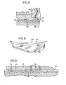
- the precise amount by which the fifth guide 86 projects downward at the leading edge 100 toward the upper surface 48 of the disc 42 is determined by thicknesses of the coins being processed. More particularly, the distance of the fifth guide 86 above the upper surface 48 is to be less than the height of a double stack of the thinnest coins being sorted, i.e., for United States coinage, a double stack of dimes. As such, the leading edge 100 of the fifth guide 86 knocks the upper dime off the stack (see Fig. 7). With some coinage, the thickness of the thicker coins being sorted is very close to the height of a double stack of the thinner coins.
- the fourth guide 84 is positioned radially inward from the peripheral third guide 82 and in front of the fifth guide by a distance approximately equal to or greater than the diameter of the thinnest coin to be processed, which, when double stacked, presents the stacking problem described above.
- the fourth guide 84 projects downward from the lower surface 64 of the head 12 toward the upper surface 48 of the disc 42 with a gradual sloping or ramp profile along a leading end portion 106 of the fourth guide, and projects downward with a gradual sloping or ramp profile along a radially outward portion 107.
- the fourth guide 84 also has a radial-1.
- the fourth guide 84 has an upwardly inclined trailing end portion 111. Another function believed served by the fourth guide 84 is to stabilize and hold flat all coins in preparation for their passage under the fifth guide 86, and avoids the problems which can result from coin vibration. Should a coin, for some reason, not be sufficiently depressed and engage the leading edge 100, a recirculation passageway 108 is provided between the second and fifth guides 80 and 86 to allow the coin to pass back into the recirculation area 88. As will be described below, the knocked off top coin of the double stack of the thinnest coins also passes back into the recirculation area 88 through the recirculation passageway 108.
- the positioning of the fourth guide 84 apart from the third guide 82 by at least the diameter of the thinnest coin allows a stack of the thinnest coins to pass between the third and fourth guides without being pressed into the relsilient pad 68 by the fourth guide and, consequently, when reaching the fifth guide 86, the leading edge 100 of the fifth guide knocks off the top coin. Since the thicker coins generally have a diameter greater than the diameter of the thinnest coin, the thicker coins in the queue which is formed along the third guide 82 will not avoid the fourth guide 84, and will be pressed into the resilient pad 68 by the fourth guide for passage under the fifth guide unimpeded by the leading edge 100 of the fifth guide.
- the space provided between the third and fourth guide also helps prevent edge-stacked, smaller diameter coins from both passing under the fifth guide 86 into the sorter channel 102.
- the positioning of the fourth cuide 84 apart from the fifth guide 86 by at least the diameter of the thinnest coin allows the knocked off top coin of the double stack of the thinnest coins to pass between the fourth and fifth guides and back into the recirculation area 88 through the recirculation passageway 108.
- the coins passing under the fifth guide fb and into the sorter channel 102 are arranged and positioned in a single layer, in single file.
- the coins travel through and leave the sorting channel 102 under the influence of the rotating disc 42, whereupon they are free of any control by the head.
- the disc 42 then carries the coins in a queue which is positioned adjacent to the peripheral rim 66 of the disc to the coin-engaging means 77 for sorting by denomination.
- the coin-engaging means comprises a plurality of coin-depressing sorting wheels 110, rotatably mounted to the head 12 and spaced along the outer perimeter of the head.
- the sorting wheels 110 extend from the head by varying distances corresponding to the diameter of the coin to be depressed, with the largest diameter coin being sorted first, then the next largest second, and so on.
- the apparatus 10 will process and sort six denominations of coins in the same batch, i.e., penny, nickel, dime, quarter, half-dollar and Susan B. Anthony dollar coins.
- the sorting wheel 110 depresses the inner edge of a coin into the resilient pad 68 causing the outer edge to raise and be hurled over the peripheral rim 66 of the disc 42 by the centrifugal force into a coin catching device 112.
- the coins are counted by an electro-optical sensor 114 as the coins are travelling through the air.
- One catching device 112 is positioned across from each sorting wheel 110.
- a last wheel 116 is provided of a width sufficient to engage all diameter coins being processed and cause a coin to be sufficiently pressed into the resilient pad 68 and bounced upwardly therefrom by resiliency of the pad that the centrifugal force will hurl it off the disc 42 into a chute 118 which diverts the coin into a special holding compartment (not shown).
Landscapes
- Physics & Mathematics (AREA)
- General Physics & Mathematics (AREA)
- Testing Of Coins (AREA)
Applications Claiming Priority (2)
| Application Number | Priority Date | Filing Date | Title |
|---|---|---|---|
| US526420 | 1983-08-25 | ||
| US06/526,420 US4564037A (en) | 1983-08-25 | 1983-08-25 | Coin-queueing head for high-speed coin-sorting and counting apparatus |
Publications (2)
| Publication Number | Publication Date |
|---|---|
| EP0137265A2 true EP0137265A2 (fr) | 1985-04-17 |
| EP0137265A3 EP0137265A3 (fr) | 1987-09-02 |
Family
ID=24097263
Family Applications (1)
| Application Number | Title | Priority Date | Filing Date |
|---|---|---|---|
| EP84110130A Withdrawn EP0137265A3 (fr) | 1983-08-25 | 1984-08-24 | Tête de séparation pour pièces de monnaie, destinée à une trieuse-compteuse de pièces de monnaie à grande vitesse |
Country Status (6)
| Country | Link |
|---|---|
| US (1) | US4564037A (fr) |
| EP (1) | EP0137265A3 (fr) |
| JP (1) | JPS60101688A (fr) |
| AU (1) | AU3235084A (fr) |
| BR (1) | BR8404249A (fr) |
| ZA (1) | ZA846496B (fr) |
Cited By (4)
| Publication number | Priority date | Publication date | Assignee | Title |
|---|---|---|---|---|
| WO1987002492A1 (fr) * | 1985-10-17 | 1987-04-23 | Childers Corporation | Tete en spirale de mise en file d'attente de pieces de monnaie pour dispositifs de comptage et de tri a haute vitesse de pieces de monnaie |
| FR2619464A1 (fr) * | 1987-08-12 | 1989-02-17 | Amiel Electronique Sa | Trieuse pour pieces de monnaie |
| NL1002712C2 (nl) * | 1996-03-26 | 1997-09-30 | Suzo International Nl B V | Muntafgifte-inrichting. |
| EP0831430A3 (fr) * | 1996-09-20 | 1999-02-03 | Asahi Seiko Kabushiki Kaisha | Dispositif pour distribuer des disques en métal |
Families Citing this family (29)
| Publication number | Priority date | Publication date | Assignee | Title |
|---|---|---|---|---|
| US4731043A (en) * | 1983-12-14 | 1988-03-15 | Ristvedt-Johnson, Inc. | Coin sorter |
| US4607649A (en) * | 1983-12-21 | 1986-08-26 | Brandt, Inc. | Coin sorter |
| US4753624A (en) * | 1987-03-27 | 1988-06-28 | Brandt, Inc. | Resilient disc coin sorter having recesses converging in the direction of coin travel |
| US5194037A (en) * | 1987-04-01 | 1993-03-16 | Cummins-Allison Corp. | Disc-type coin sorting mechanism for sorting coins by radial locations of the inner edges of the coins |
| US4775354A (en) * | 1987-06-29 | 1988-10-04 | Cummins-Allison Corp. | Coin sorting apparatus with rotating disc stationary guide plate for sorting coins by their different diameters |
| US4966570A (en) * | 1987-07-30 | 1990-10-30 | Ristvedt Victor G | Coin sorting apparatus for sorting coins of selected denominations |
| US5104353A (en) * | 1987-07-30 | 1992-04-14 | Ristvdet-Johnson, Inc. | Coin sorting apparatus with rotating disc |
| US5009627A (en) * | 1989-03-14 | 1991-04-23 | Cummins-Allison Corp. | Coin sorting mechanism |
| US5141472A (en) * | 1990-10-30 | 1992-08-25 | Cummins-Allison Corp. | Disc-type coin sorter with adjustable gaging device |
| US5205780A (en) * | 1991-04-29 | 1993-04-27 | Cummins-Allison Corporation | Disc-type coin sorter with eccentric feed |
| US5163866A (en) * | 1991-04-29 | 1992-11-17 | Cummins-Allison Corp. | Disc-type coin sorter with multiple-path queuing |
| US5163867A (en) * | 1991-05-15 | 1992-11-17 | Cummins-Allison Corp. | Disc-type coin sorter with multiple-path queuing |
| US5145455A (en) * | 1991-05-15 | 1992-09-08 | Cummins-Allison Corp. | Wave-type coin sorter |
| WO1992022044A1 (fr) * | 1991-06-03 | 1992-12-10 | Cummins-Allison Corp. | Trieuse de pieces de monnaie a disque |
| US5372542A (en) * | 1993-07-09 | 1994-12-13 | Cummins-Allison Corp. | Disc coin sorter with improved exit channel |
| US5468182A (en) * | 1993-08-05 | 1995-11-21 | Cummins-Allison Corp. | Disc-type coin sorter with adjustable targeting inserts |
| US5401211A (en) * | 1993-08-05 | 1995-03-28 | Cummins-Allison Corp. | Disc coin sorter with positive guide wall between exit channels |
| US5514034A (en) * | 1993-09-28 | 1996-05-07 | Cummins-Allison Corp. | Apparatus and method for terminating coin sorting using pressureless exit channels and immediate stopping |
| US5370575A (en) * | 1994-01-06 | 1994-12-06 | Cummins-Allison Corp. | Coin sorting mechanism |
| US5501631A (en) * | 1994-01-06 | 1996-03-26 | Cummins-Allison Corp. | Coin handling device with an improved lubrication system |
| US5425669A (en) * | 1994-01-07 | 1995-06-20 | Cummins-Allison Corp. | Coin queuing and sorting arrangement |
| US5542881A (en) * | 1995-04-28 | 1996-08-06 | Cummins-Allison Corp. | Coin sorting mechanism having dual recycle channels |
| US5997395A (en) * | 1998-03-17 | 1999-12-07 | Cummins-Allison Corp. | High speed coin sorter having a reduced size |
| JP4002967B2 (ja) * | 2002-08-27 | 2007-11-07 | 旭精工株式会社 | ディスクのホッパー |
| US7472780B2 (en) * | 2003-05-06 | 2009-01-06 | Royal Sovereign Inc. | Coin sorting apparatus, control system for controlling coin sorting apparatus, and method for sorting coins |
| US7658668B2 (en) * | 2005-09-17 | 2010-02-09 | Scan Coin Ab | Coin handling equipment |
| EP1938283B1 (fr) * | 2005-09-17 | 2009-12-02 | Scan Coin Ab | Equipement de manipulation de pieces |
| US8540548B2 (en) * | 2010-10-04 | 2013-09-24 | Tech 4 Kids, Inc. | Child's activity toy and disc dispenser therefor |
| US11847879B2 (en) | 2020-07-31 | 2023-12-19 | Cummins-Allison Corp. | Coin sorting disc with coin flow management features |
Family Cites Families (12)
| Publication number | Priority date | Publication date | Assignee | Title |
|---|---|---|---|---|
| US2348936A (en) * | 1940-10-11 | 1944-05-16 | Brandt Automatic Cashier Co | Coin sorting and counting machine |
| US2906276A (en) * | 1956-03-08 | 1959-09-29 | Brandt Automatic Cashier Co | Coin sorter |
| US2977961A (en) * | 1957-12-06 | 1961-04-04 | Brandt Automatic Cashier Co | Coin sorting machine |
| US3795252A (en) * | 1972-11-20 | 1974-03-05 | Westermann W | Centrifugal coin sorter |
| US3939954A (en) * | 1974-03-18 | 1976-02-24 | Qonaar Corporation | Check receiving and testing apparatus |
| US3998237A (en) * | 1975-04-25 | 1976-12-21 | Brandt, Inc. | Coin sorter |
| CH596616A5 (fr) * | 1976-04-01 | 1978-03-15 | Systems & Technics Sa | |
| US4086928A (en) * | 1976-08-06 | 1978-05-02 | Ristvedt Victor G | Coin sorting machine |
| US4098280A (en) * | 1976-10-22 | 1978-07-04 | Ristvedt Victor G | Coin handling machine |
| US4234003A (en) * | 1978-06-30 | 1980-11-18 | Ristvedt Victor G | Coin handling machine |
| DE2912016C2 (de) * | 1979-03-24 | 1981-10-08 | F.Zimmermann & Co., 1000 Berlin | Vereinzelungsvorrichtung für Münzen |
| US4506685A (en) * | 1982-04-19 | 1985-03-26 | Childers Roger K | High-speed coin sorting and counting apparatus |
-
1983
- 1983-08-25 US US06/526,420 patent/US4564037A/en not_active Expired - Fee Related
-
1984
- 1984-08-21 ZA ZA846496A patent/ZA846496B/xx unknown
- 1984-08-24 EP EP84110130A patent/EP0137265A3/fr not_active Withdrawn
- 1984-08-24 BR BR8404249A patent/BR8404249A/pt unknown
- 1984-08-24 JP JP59176519A patent/JPS60101688A/ja active Pending
- 1984-08-24 AU AU32350/84A patent/AU3235084A/en not_active Abandoned
Cited By (5)
| Publication number | Priority date | Publication date | Assignee | Title |
|---|---|---|---|---|
| WO1987002492A1 (fr) * | 1985-10-17 | 1987-04-23 | Childers Corporation | Tete en spirale de mise en file d'attente de pieces de monnaie pour dispositifs de comptage et de tri a haute vitesse de pieces de monnaie |
| FR2619464A1 (fr) * | 1987-08-12 | 1989-02-17 | Amiel Electronique Sa | Trieuse pour pieces de monnaie |
| NL1002712C2 (nl) * | 1996-03-26 | 1997-09-30 | Suzo International Nl B V | Muntafgifte-inrichting. |
| EP0831430A3 (fr) * | 1996-09-20 | 1999-02-03 | Asahi Seiko Kabushiki Kaisha | Dispositif pour distribuer des disques en métal |
| US6039166A (en) * | 1996-09-20 | 2000-03-21 | Asahi Seiko Kebushiki Kaisha | Metal disc ejector |
Also Published As
| Publication number | Publication date |
|---|---|
| AU3235084A (en) | 1985-02-28 |
| US4564037A (en) | 1986-01-14 |
| BR8404249A (pt) | 1985-07-23 |
| EP0137265A3 (fr) | 1987-09-02 |
| ZA846496B (en) | 1985-03-27 |
| JPS60101688A (ja) | 1985-06-05 |
Similar Documents
| Publication | Publication Date | Title |
|---|---|---|
| US4564037A (en) | Coin-queueing head for high-speed coin-sorting and counting apparatus | |
| CA1291066C (fr) | Tete helicoidale de disposition de monnaies en enfilade pour machine de triet de comptage haute vitesse | |
| US4506685A (en) | High-speed coin sorting and counting apparatus | |
| US6612921B2 (en) | High speed coin sorter having a reduced size | |
| US4234003A (en) | Coin handling machine | |
| US4549561A (en) | Coin handling machine | |
| US4531531A (en) | Coin handling machine | |
| US4444212A (en) | Coin handling machine | |
| US4098280A (en) | Coin handling machine | |
| US5542881A (en) | Coin sorting mechanism having dual recycle channels | |
| US4731043A (en) | Coin sorter | |
| US4753624A (en) | Resilient disc coin sorter having recesses converging in the direction of coin travel | |
| US8844704B2 (en) | Money item dispensing apparatus | |
| CA1271162A (fr) | Trieuse de monnaies | |
| EP0137266A2 (fr) | Roue et compteur pour le tri de pièces de monnaie destinés à une trieuse-compteuse à grande vitesse | |
| KR100512053B1 (ko) | 코인배분장치 | |
| JPH02126387A (ja) | コイン・ソーター | |
| US5607351A (en) | Coin counting machine | |
| US4466453A (en) | Coin counting and sorting apparatus | |
| JP3766130B2 (ja) | 硬貨払出装置 | |
| US20240096161A1 (en) | Coin sorting disc with coin flow management features | |
| JP3950949B2 (ja) | コインの金種振り分け装置 | |
| JP2593711Y2 (ja) | 硬貨分類装置 | |
| CA1278275C (fr) | Appareil de tri et de comptage rapide de pieces de monnaie | |
| JP2018092257A (ja) | 硬貨繰出装置 |
Legal Events
| Date | Code | Title | Description |
|---|---|---|---|
| PUAI | Public reference made under article 153(3) epc to a published international application that has entered the european phase |
Free format text: ORIGINAL CODE: 0009012 |
|
| AK | Designated contracting states |
Designated state(s): AT BE CH DE FR GB IT LI LU NL SE |
|
| PUAL | Search report despatched |
Free format text: ORIGINAL CODE: 0009013 |
|
| AK | Designated contracting states |
Kind code of ref document: A3 Designated state(s): AT BE CH DE FR GB IT LI LU NL SE |
|
| STAA | Information on the status of an ep patent application or granted ep patent |
Free format text: STATUS: THE APPLICATION IS DEEMED TO BE WITHDRAWN |
|
| 18D | Application deemed to be withdrawn |
Effective date: 19880502 |
|
| RIN1 | Information on inventor provided before grant (corrected) |
Inventor name: TRUMBO, ANDREW L. Inventor name: CHILDERS, ROGER, K. |