EP0137344A2 - Signalgeber für ein optisches Kabel mit einer Fiber - Google Patents
Signalgeber für ein optisches Kabel mit einer Fiber Download PDFInfo
- Publication number
- EP0137344A2 EP0137344A2 EP84110969A EP84110969A EP0137344A2 EP 0137344 A2 EP0137344 A2 EP 0137344A2 EP 84110969 A EP84110969 A EP 84110969A EP 84110969 A EP84110969 A EP 84110969A EP 0137344 A2 EP0137344 A2 EP 0137344A2
- Authority
- EP
- European Patent Office
- Prior art keywords
- cable
- light
- optical fibre
- remote location
- switching system
- Prior art date
- Legal status (The legal status is an assumption and is not a legal conclusion. Google has not performed a legal analysis and makes no representation as to the accuracy of the status listed.)
- Withdrawn
Links
- 239000013307 optical fiber Substances 0.000 title claims abstract description 31
- 230000011664 signaling Effects 0.000 title abstract description 4
- 230000008859 change Effects 0.000 claims abstract description 9
- 230000004044 response Effects 0.000 claims abstract description 9
- 239000000835 fiber Substances 0.000 claims description 19
- 230000005540 biological transmission Effects 0.000 claims description 4
- 230000003287 optical effect Effects 0.000 description 6
- 230000008878 coupling Effects 0.000 description 5
- 238000010168 coupling process Methods 0.000 description 5
- 238000005859 coupling reaction Methods 0.000 description 5
- 238000004891 communication Methods 0.000 description 4
- 239000000463 material Substances 0.000 description 4
- 230000009471 action Effects 0.000 description 3
- 238000000034 method Methods 0.000 description 3
- 239000012141 concentrate Substances 0.000 description 2
- 230000004048 modification Effects 0.000 description 2
- 238000012986 modification Methods 0.000 description 2
- 239000003973 paint Substances 0.000 description 2
- 230000005855 radiation Effects 0.000 description 2
- 239000011358 absorbing material Substances 0.000 description 1
- 239000011324 bead Substances 0.000 description 1
- 238000005452 bending Methods 0.000 description 1
- 239000011248 coating agent Substances 0.000 description 1
- 238000000576 coating method Methods 0.000 description 1
- 238000010276 construction Methods 0.000 description 1
- 230000001419 dependent effect Effects 0.000 description 1
- 230000000994 depressogenic effect Effects 0.000 description 1
- 238000010586 diagram Methods 0.000 description 1
- XDDAORKBJWWYJS-UHFFFAOYSA-N glyphosate Chemical compound OC(=O)CNCP(O)(O)=O XDDAORKBJWWYJS-UHFFFAOYSA-N 0.000 description 1
- 230000008520 organization Effects 0.000 description 1
- 230000008569 process Effects 0.000 description 1
- 238000000926 separation method Methods 0.000 description 1
- 239000007787 solid Substances 0.000 description 1
- 230000000007 visual effect Effects 0.000 description 1
Images
Classifications
-
- G—PHYSICS
- G02—OPTICS
- G02B—OPTICAL ELEMENTS, SYSTEMS OR APPARATUS
- G02B6/00—Light guides; Structural details of arrangements comprising light guides and other optical elements, e.g. couplings
- G02B6/24—Coupling light guides
- G02B6/26—Optical coupling means
- G02B6/35—Optical coupling means having switching means
- G02B6/354—Switching arrangements, i.e. number of input/output ports and interconnection types
- G02B6/3544—2D constellations, i.e. with switching elements and switched beams located in a plane
- G02B6/3548—1xN switch, i.e. one input and a selectable single output of N possible outputs
- G02B6/3552—1x1 switch, e.g. on/off switch
-
- G—PHYSICS
- G02—OPTICS
- G02B—OPTICAL ELEMENTS, SYSTEMS OR APPARATUS
- G02B6/00—Light guides; Structural details of arrangements comprising light guides and other optical elements, e.g. couplings
- G02B6/24—Coupling light guides
-
- G—PHYSICS
- G02—OPTICS
- G02B—OPTICAL ELEMENTS, SYSTEMS OR APPARATUS
- G02B6/00—Light guides; Structural details of arrangements comprising light guides and other optical elements, e.g. couplings
- G02B6/24—Coupling light guides
- G02B6/26—Optical coupling means
- G02B6/264—Optical coupling means with optical elements between opposed fibre ends which perform a function other than beam splitting
- G02B6/266—Optical coupling means with optical elements between opposed fibre ends which perform a function other than beam splitting the optical element being an attenuator
-
- G—PHYSICS
- G02—OPTICS
- G02B—OPTICAL ELEMENTS, SYSTEMS OR APPARATUS
- G02B6/00—Light guides; Structural details of arrangements comprising light guides and other optical elements, e.g. couplings
- G02B6/24—Coupling light guides
- G02B6/26—Optical coupling means
- G02B6/35—Optical coupling means having switching means
- G02B6/3564—Mechanical details of the actuation mechanism associated with the moving element or mounting mechanism details
- G02B6/3568—Mechanical details of the actuation mechanism associated with the moving element or mounting mechanism details characterised by the actuating force
- G02B6/3574—Mechanical force, e.g. pressure variations
-
- G—PHYSICS
- G02—OPTICS
- G02B—OPTICAL ELEMENTS, SYSTEMS OR APPARATUS
- G02B6/00—Light guides; Structural details of arrangements comprising light guides and other optical elements, e.g. couplings
- G02B6/24—Coupling light guides
- G02B6/26—Optical coupling means
- G02B6/35—Optical coupling means having switching means
- G02B6/351—Optical coupling means having switching means involving stationary waveguides with moving interposed optical elements
- G02B6/3512—Optical coupling means having switching means involving stationary waveguides with moving interposed optical elements the optical element being reflective, e.g. mirror
- G02B6/3514—Optical coupling means having switching means involving stationary waveguides with moving interposed optical elements the optical element being reflective, e.g. mirror the reflective optical element moving along a line so as to translate into and out of the beam path, i.e. across the beam path
-
- G—PHYSICS
- G02—OPTICS
- G02B—OPTICAL ELEMENTS, SYSTEMS OR APPARATUS
- G02B6/00—Light guides; Structural details of arrangements comprising light guides and other optical elements, e.g. couplings
- G02B6/24—Coupling light guides
- G02B6/26—Optical coupling means
- G02B6/35—Optical coupling means having switching means
- G02B6/351—Optical coupling means having switching means involving stationary waveguides with moving interposed optical elements
- G02B6/353—Optical coupling means having switching means involving stationary waveguides with moving interposed optical elements the optical element being a shutter, baffle, beam dump or opaque element
-
- G—PHYSICS
- G02—OPTICS
- G02B—OPTICAL ELEMENTS, SYSTEMS OR APPARATUS
- G02B6/00—Light guides; Structural details of arrangements comprising light guides and other optical elements, e.g. couplings
- G02B6/24—Coupling light guides
- G02B6/26—Optical coupling means
- G02B6/35—Optical coupling means having switching means
- G02B6/3586—Control or adjustment details, e.g. calibrating
- G02B6/3588—Control or adjustment details, e.g. calibrating of the processed beams, i.e. controlling during switching of orientation, alignment, or beam propagation properties such as intensity, size or shape
Definitions
- the present invention relates to optical fibre signaling systems and, mor particularly, to optical fibre signaling systems which are employed to transmit a change in condition from a remote point to a central location.
- a source of unmodulated light at the central station is provided together with bi-directional coupling means connected between the light source and a single optical fibre cable at the central station.
- a shutter element at the remote location is movable between first and second positions in response to a change in the measured variable, the other end of the single optical fibre cable being terminated within a housing in cooperating relation to the movable shutter element, said shutter element and the interior of the housing having cooperating light reflecting and light absorbing surfaces which are effective in one position of the shutter element to absorb unmodulated light transmitted from the source over said cable to said remote location and prevent the same from being transmitted back over said cable to said bi-directional coupling means and effective in the other position of said shutter element to reflect unmodulated light transmitted to said remote location back over the cable to the bi-directional coupling means.
- An annunciator or other alarm system is coupled to the bi-directional coupling means at the central station and is responsive to reflected unmodulated light transmitted back over the single cable when the shutter element is in said other position for developing a suitable indication or alarm signal
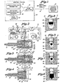
- Fig. 1 the present invention is therein-illustrated in connection with an annunciator system in which signals from a plurality of remote locations are supplied to a central station indicated generally at 10, one of these remote stations being indicated by a remote condition indicating device 12, the central station 10 being connec- te d to each remote device 12 by means of a single optical fibre cable 14.
- a remote condition indicating device 12 the central station 10 being connec- te d to each remote device 12 by means of a single optical fibre cable 14.
- an unmodulated light transmitter 16 is employed as an unmodulated light source the output of which is supplied to the single optical fibre cable 14 through a beam splitter or bi-directional coupling means 18.
- a light reflecting shutter which is movably positioned in relation to the remote end of the cable 14 in accordance with the occurrence of a predetermined condition or event.
- a movable shutter arrangement such as shown in our aforementioned European patent application No. 83 109 136.8 is modified to provide such a device, as will be described in more detail hereinafter.
- a movable shutter 30 is slideably mounted for vertical movement within a housing 32 and extends downwardly into an offset central portion 34 within which are mounted a pair of optical fibre cable bushings 36 and 38.
- the bushings 36, 38 are mounted within the offset portion 36 by means of the alignment procedure described in our aforementioned European patent application No. 83 109 136.8 so that the shutter 30 is exactly perpendicular to the central axis of the two bushings 36, 38.
- the single optical fibre cable 14 of Fig. 1 is terminated in an optical fibre terminating ferrule 40 which is received within the bushing 36 and is secured therewithin by means of an end cap 42.
- Movement of the shutter 30 is controlled by means of an actuating member 44 one end of which is rigidly mounted in the housing 32 and the other end of which extends through a slot in the shutter 30.
- the actuating member 44 is held in an uppermost position by means of a pair of bowed spring arms 46 and an actuator pin 48 is mounted in the top wall of the housing 32 and includes a head portion 50 in engagement with the actuating member 44.
- the actuator pin 48 When a downward force is exerted on the actuator pin 48 in response to the occurrence of a predetermined event or condition, the actuator member 44 is moved downwardly beyond the pivot point of the spring arms 46 so that the shutter 30 is rapidly moved downwardly with a snap action to a position in which the bottom end of the shutter 30 is moved in front of the exposed end face of the fibre optic cable 14.
- no optical fibre cable is mounted in the bushing 38 and a solid end cap 60 is threaded onto the end of the bushing 38 in place of the standard end cap 42.
- the inner surfaces 62 of the end cap 60 are painted black or otherwise rendered light absorptive to prevent the reflection of light from these surfaces.
- the inner surfaces 64, 66 and the end face 68 of the bushing 38 are covered with black paint or other light absorptive material to prevent the reflection of light from these surfaces. Accordingly, when the shutter 30 is in the uppermost position shown in Fig.
- the unmodulated light which is supplied from the transmitter 16 through the beam splitter 18 to the cable 14 is absorbed by the light absorbing surfaces 62, 64, 66 and 68 provided in the remote condition indicating device 12 shown in Fig. 2 so that no light is reflected back through the beam splitter 18 to the receiver 20.
- a mirrored surface 70 which is provided on the side of the shutter 30 adjacent the end face of the cable 14, is moved into light reflecting relationship to this end face so that unmodulated light is reflected back over the single cable 14 and through the beam splitter 18 to the light receiver 20.
- the reflective surface 70 is preferably formed by vacuum metalizing an area of the shutter 30 adjacent the end of the cable 14 to provide a silvered surface which is highly light reflective for the type of light emitted by the transmitter 16.
- the transmitter 16 projects an extremely narrow beam in order to concentrate most of the available light for transmission along the single cable 14.
- the transmitter 16 is an LED light source which emits light in the near infrared range and is provided with a bead type lens to concentrate light emitted therefrom.
- the LED is mounted in a threaded bushing which may be connected directly to one input of the beam splitter 18.
- the light receiver 20 is preferably a phototransistor which responds primarily to light in the near infrared range emitted by the transmitter 16.
- the light transmitted from the transmitter 16 over the cable 14 to the remote device 12 and the light reflected back from the surface 70 over the cable 14 to the beam splitter 18 and the receiver 20 are both unmodulated and are of the same frequency. While it might appear impossible to transmit unmodulated light beams of the same frequency in opposite directions through the cable, it should be understood that the light transmitter 16 provides an extremely narrow beam of light which is transmitted along the cable 14. It has been found that while the returning light waves interfere with the transmitted light waves at their many points of juncture along the cable 14, this interference produces temporary amplitude changes but does not produce attenuation changes.
- the transmission of light beams in both directions through the cable 14 may be analogized to the situation where the headlights of two cars approaching along a highway intersect.
- the transmitted beam may be reflected by the surface 70 back along the cable 14 and through the beam splitter 18 to the light receiver 20 with an attenuation dependent only on the normal attenuation of light being transmitted through the cable 14.
- the beam splitter 18 has a high efficiency so that substantially all of the light developed by the light transmitter 16 is supplied to the input end of the cable 14 and very little is coupled to the input of the receiver 20. Similarly, substantially all of the reflected light which is reflected back over the cable 14 from the remote location 12 is supplied to the light receiver 20 and very little light is coupled into the light transmitter 16.
- the beam splitter 18 may be of any suitable construction, a one-way mirror type of beam splitter such as shown, for example, in Kiernan et al U.S. patent No. 4,262,362 is preferably employed.
- the light reflective surface 70 on the shutter 30 and to provide the light absorbing surfaces 62-68 it is also possible to provide, in accordance with the present invention, an arrangement in which the shutter 30 is provided with a blackened, light absorptive surface 70A adjacent the side thereof which is positioned over the end face of the cable 14, as shown in Fig. 6, and to coat the surfaces 62, 64, 66 and 68 with a material which is highly light reflective. In such an arrangement, the light transmitted over the cable 14 from the transmitter 16 is reflected back over the cable 14 and through the beam splitter 18 to the receiver 20 when the shutter 30 is in the uppermost position shown in Fig. 2.
- Fig. 3 an alternative embodiment of the invention is shown which differs from that of Fig. 2 in that a standard end cap 80 is employed to hold an insert 82 against the end face of the bushing 38.
- the internal surface 64, 66 of the bushing 38 are coated with black paint, or other light absorbing material, as in the embodiment of Fig. 2, and the insert 80 is provided with a light absorptive surface 84 adjacent the end of the bushing 38 so as to totally absorb light transmitted over the cable 14 when the shutter 30 is in the uppermost position shown in Fig. 3.
- the light reflective surface 70 is moved downwardly over the end face of the cable 14 and reflects light back over the cable 14 and through the beam splitter 18 to the receiver 20 in a manner identical to that described in detail heretofore in connection with Fig. 2.
- the light reflective and light absorptive surfaces may be reversed, i.e. the surfaces 64, 66 and 84 may be coated with a material which is highly light reflective and the shutter 30 may be coated with a light absorptive coating instead of the reflective surface 70.
- a further alternative embodiment of the present invention is illustrated wherein the bushing 38 of Figs. 2 and 3 is eliminated and a hexagonally shaped plate 90 which is of the same thickness and shape as the flanged portion of the bushing 38, is mounted in the offset portion 34.
- the offset portion 34 is provided with inwardly extending rib portions 92 and 94 within which the plate 90 may be conveniently mounted and secured.
- the shutter 30 is again provided with the light reflective surface 70, as described in the other embodiments of the invention and the plate 90 is provided with a light absorptive surface on the side adjacent to and opposite the end face of the optical fibre cable 14.
- the light reflective and light absorptive surfaces may again be reversed, in which case the plate 90 will be provided with a light reflective surface in the area opposite to and adjacent the end face of the cable 14 and the shutter 30 is coated with a light absorptive material so that when this shutter is moved to its downward position over the end of the cable 14 all transmitted light will be absorbed.
- the shutter 30 may be somewhat longer so that it extends over the end face of the cable 14 when it is in its uppermost position and a hole may be provided in this shutter which is moved into alignment with the end face of the cable when the pin 48 is actuated and this shutter is moved downwardly.
Landscapes
- Physics & Mathematics (AREA)
- General Physics & Mathematics (AREA)
- Optics & Photonics (AREA)
- Mechanical Light Control Or Optical Switches (AREA)
- Testing Of Optical Devices Or Fibers (AREA)
- Light Guides In General And Applications Therefor (AREA)
- Monitoring And Testing Of Transmission In General (AREA)
- Optical Communication System (AREA)
- Arrangements For Transmission Of Measured Signals (AREA)
Applications Claiming Priority (2)
| Application Number | Priority Date | Filing Date | Title |
|---|---|---|---|
| US531933 | 1983-09-13 | ||
| US06/531,933 US4556280A (en) | 1983-09-13 | 1983-09-13 | Single cable optical fibre signaling system |
Publications (2)
| Publication Number | Publication Date |
|---|---|
| EP0137344A2 true EP0137344A2 (de) | 1985-04-17 |
| EP0137344A3 EP0137344A3 (de) | 1987-08-19 |
Family
ID=24119660
Family Applications (1)
| Application Number | Title | Priority Date | Filing Date |
|---|---|---|---|
| EP84110969A Withdrawn EP0137344A3 (de) | 1983-09-13 | 1984-09-13 | Signalgeber für ein optisches Kabel mit einer Fiber |
Country Status (4)
| Country | Link |
|---|---|
| US (1) | US4556280A (de) |
| EP (1) | EP0137344A3 (de) |
| JP (1) | JPS6090444A (de) |
| CA (1) | CA1247414A (de) |
Cited By (1)
| Publication number | Priority date | Publication date | Assignee | Title |
|---|---|---|---|---|
| EP0226726A3 (de) * | 1985-10-28 | 1989-08-16 | Elektro-Apparatebau Olten AG | Optische Schalteinrichtung |
Families Citing this family (19)
| Publication number | Priority date | Publication date | Assignee | Title |
|---|---|---|---|---|
| US4672199A (en) * | 1984-03-02 | 1987-06-09 | Fiberdynamics, Inc. | Fiberoptic temperature/pressure sensor system |
| US4753501A (en) * | 1986-01-15 | 1988-06-28 | The United States Of America As Represented By The Secretary Of The Air Force | Fiber optic rotary switching device |
| US4789215A (en) * | 1986-04-18 | 1988-12-06 | Northern Telecom Limited | Fiber optic switch with prism mounted for reciprocal and rotational movement |
| US4733561A (en) * | 1986-07-21 | 1988-03-29 | The Foxboro Company | Self-oscillating, optical resonant sensor |
| JPS63174740U (de) * | 1987-02-28 | 1988-11-14 | ||
| US5170446A (en) * | 1988-09-09 | 1992-12-08 | Square D Company | Rotational optical switch |
| US4964693A (en) * | 1989-03-28 | 1990-10-23 | Motorola, Inc. | Radio having optical controls and method of optically controlling same |
| US5162935A (en) * | 1991-06-19 | 1992-11-10 | The United States Of America As Represented By The Department Of Energy | Fiber optically isolated and remotely stabilized data transmission system |
| US5333205A (en) * | 1993-03-01 | 1994-07-26 | Motorola, Inc. | Microphone assembly |
| US5513286A (en) * | 1994-06-08 | 1996-04-30 | Syntec, Inc. | White light dimmer for fiber optic illumination sources |
| US5486058A (en) * | 1994-08-09 | 1996-01-23 | Allen; Donald E. | Continuous touch keyboard |
| US5956444A (en) * | 1997-02-13 | 1999-09-21 | Amphenol Corporation | Radiation absorbing shield for fiber optic systems |
| US6047250A (en) | 1997-04-21 | 2000-04-04 | Management And Report Technologies, Inc. | System for monitoring fluid distribution and associated methods |
| US5902938A (en) * | 1997-04-21 | 1999-05-11 | Management And Report Technologies, Inc. | Explosive fluid metering apparatus having immune data converter and method of metering explosive fluid distribution |
| US6002216A (en) * | 1998-06-26 | 1999-12-14 | Cedars-Sinai Medical Center | Pool lighting system, illuminator, and method therefore |
| US6173105B1 (en) * | 1998-11-20 | 2001-01-09 | Lucent Technologies | Optical attenuator |
| US7526154B2 (en) * | 2006-06-16 | 2009-04-28 | Verizon Services Corp. | Cover for optical fibers and/or optical devices |
| US8515218B2 (en) | 2010-10-28 | 2013-08-20 | Kevin HIBBARD | Light redirection system and methods of forming same |
| DE102011108371B4 (de) * | 2011-07-22 | 2014-12-31 | Advanced Optics Solutions Gmbh | Überwachungssystem für Glasfaser-Netzverteiler |
Family Cites Families (8)
| Publication number | Priority date | Publication date | Assignee | Title |
|---|---|---|---|---|
| US4170731A (en) * | 1976-08-30 | 1979-10-09 | Miller Fluid Power Corporation | Fiber optic control modules and system employing the same |
| US4223217A (en) * | 1977-05-12 | 1980-09-16 | Eaton Corporation | Fiber optic electric switch |
| US4155005A (en) * | 1977-09-08 | 1979-05-15 | Valtec Corporation | Fiber optic control system |
| US4195269A (en) * | 1978-04-19 | 1980-03-25 | Rca Corporation | Two-way single fiber optical communication system |
| US4262362A (en) * | 1978-10-18 | 1981-04-14 | Westinghouse Electric Corp. | Fiber optics duplex module |
| US4249794A (en) * | 1979-03-21 | 1981-02-10 | Fmc Corporation | Optically coupled remote control system |
| US4376566A (en) * | 1980-03-03 | 1983-03-15 | Sheltered Workshop For The Disabled, Inc. | Fiber optic switching method and apparatus with flexible shutter |
| JPH0414725Y2 (de) * | 1980-09-30 | 1992-04-02 |
-
1983
- 1983-09-13 US US06/531,933 patent/US4556280A/en not_active Expired - Fee Related
-
1984
- 1984-09-07 CA CA000462646A patent/CA1247414A/en not_active Expired
- 1984-09-13 JP JP59192436A patent/JPS6090444A/ja active Pending
- 1984-09-13 EP EP84110969A patent/EP0137344A3/de not_active Withdrawn
Cited By (1)
| Publication number | Priority date | Publication date | Assignee | Title |
|---|---|---|---|---|
| EP0226726A3 (de) * | 1985-10-28 | 1989-08-16 | Elektro-Apparatebau Olten AG | Optische Schalteinrichtung |
Also Published As
| Publication number | Publication date |
|---|---|
| EP0137344A3 (de) | 1987-08-19 |
| CA1247414A (en) | 1988-12-28 |
| JPS6090444A (ja) | 1985-05-21 |
| US4556280A (en) | 1985-12-03 |
Similar Documents
| Publication | Publication Date | Title |
|---|---|---|
| US4556280A (en) | Single cable optical fibre signaling system | |
| EP0506847B1 (de) | Faseroptischer schalter mit einem sphärischen reflektor | |
| US8724944B2 (en) | Fiber optic bi-directional coupling lens | |
| US4516828A (en) | Duplex communication on a single optical fiber | |
| US5146516A (en) | Optoelectrical sending and receiving apparatus | |
| US5261015A (en) | Magnetically-actuatable opto-mechanical on/off switch and systems for use therewith | |
| US4521683A (en) | Pressure-actuated optical switch | |
| US4812003A (en) | Optic sensing assembly | |
| US4678902A (en) | Fiber optic transducers with improved sensitivity | |
| JPH0510615B2 (de) | ||
| KR100829409B1 (ko) | 윈도우의 습윤 검출용 센서 장치 | |
| US4333009A (en) | Optical position transducer | |
| EP0167220B1 (de) | Optischer Umsetzer und Messanordnung | |
| CN110596828A (zh) | 一种光模块 | |
| US5892862A (en) | Flexible mirror optical switch | |
| EP0107374B1 (de) | Wegmesseinrichtung | |
| US7489841B2 (en) | Device for transferring optical signals by means of planar optical conductors | |
| CA1323225C (en) | Fiber optic control system | |
| EP0289185B1 (de) | Optische Sensoranordnung | |
| GB2144557A (en) | Optical coupler | |
| JPH047051B2 (de) | ||
| EP0177928A1 (de) | Lichtwellenleiter, insbesondere optische Faser | |
| US5250805A (en) | Optical sensing technique providing built in test | |
| GB2046897A (en) | Window or like member | |
| JPS6358328B2 (de) |
Legal Events
| Date | Code | Title | Description |
|---|---|---|---|
| PUAI | Public reference made under article 153(3) epc to a published international application that has entered the european phase |
Free format text: ORIGINAL CODE: 0009012 |
|
| AK | Designated contracting states |
Designated state(s): AT BE DE FR GB IT LU NL SE |
|
| RAP1 | Party data changed (applicant data changed or rights of an application transferred) |
Owner name: AMETEK, INC. |
|
| PUAL | Search report despatched |
Free format text: ORIGINAL CODE: 0009013 |
|
| AK | Designated contracting states |
Kind code of ref document: A3 Designated state(s): AT BE DE FR GB IT LU NL SE |
|
| 17P | Request for examination filed |
Effective date: 19871019 |
|
| 17Q | First examination report despatched |
Effective date: 19890707 |
|
| STAA | Information on the status of an ep patent application or granted ep patent |
Free format text: STATUS: THE APPLICATION HAS BEEN WITHDRAWN |
|
| 18W | Application withdrawn |
Withdrawal date: 19891002 |
|
| R18W | Application withdrawn (corrected) |
Effective date: 19891002 |
|
| RIN1 | Information on inventor provided before grant (corrected) |
Inventor name: BAGBY, ROBERT J. |