EP0137406A1 - Ensemble pour la propulsion réglable de masses importantes - Google Patents
Ensemble pour la propulsion réglable de masses importantes Download PDFInfo
- Publication number
- EP0137406A1 EP0137406A1 EP84111461A EP84111461A EP0137406A1 EP 0137406 A1 EP0137406 A1 EP 0137406A1 EP 84111461 A EP84111461 A EP 84111461A EP 84111461 A EP84111461 A EP 84111461A EP 0137406 A1 EP0137406 A1 EP 0137406A1
- Authority
- EP
- European Patent Office
- Prior art keywords
- drive
- gear
- pump
- pumps
- variable
- Prior art date
- Legal status (The legal status is an assumption and is not a legal conclusion. Google has not performed a legal analysis and makes no representation as to the accuracy of the status listed.)
- Withdrawn
Links
- 230000002706 hydrostatic effect Effects 0.000 claims abstract description 10
- 239000012530 fluid Substances 0.000 claims description 12
- 238000002485 combustion reaction Methods 0.000 claims 1
- 230000001419 dependent effect Effects 0.000 claims 1
- 230000005540 biological transmission Effects 0.000 abstract description 12
- 238000010586 diagram Methods 0.000 description 2
- 230000002093 peripheral effect Effects 0.000 description 1
- 230000001105 regulatory effect Effects 0.000 description 1
Images


Classifications
-
- B—PERFORMING OPERATIONS; TRANSPORTING
- B60—VEHICLES IN GENERAL
- B60K—ARRANGEMENT OR MOUNTING OF PROPULSION UNITS OR OF TRANSMISSIONS IN VEHICLES; ARRANGEMENT OR MOUNTING OF PLURAL DIVERSE PRIME-MOVERS IN VEHICLES; AUXILIARY DRIVES FOR VEHICLES; INSTRUMENTATION OR DASHBOARDS FOR VEHICLES; ARRANGEMENTS IN CONNECTION WITH COOLING, AIR INTAKE, GAS EXHAUST OR FUEL SUPPLY OF PROPULSION UNITS IN VEHICLES
- B60K17/00—Arrangement or mounting of transmissions in vehicles
- B60K17/04—Arrangement or mounting of transmissions in vehicles characterised by arrangement, location or kind of gearing
- B60K17/10—Arrangement or mounting of transmissions in vehicles characterised by arrangement, location or kind of gearing of fluid gearing
-
- F—MECHANICAL ENGINEERING; LIGHTING; HEATING; WEAPONS; BLASTING
- F16—ENGINEERING ELEMENTS AND UNITS; GENERAL MEASURES FOR PRODUCING AND MAINTAINING EFFECTIVE FUNCTIONING OF MACHINES OR INSTALLATIONS; THERMAL INSULATION IN GENERAL
- F16H—GEARING
- F16H47/00—Combinations of mechanical gearing with fluid clutches or fluid gearing
- F16H47/02—Combinations of mechanical gearing with fluid clutches or fluid gearing the fluid gearing being of the volumetric type
- F16H47/04—Combinations of mechanical gearing with fluid clutches or fluid gearing the fluid gearing being of the volumetric type the mechanical gearing being of the type with members having orbital motion
-
- F—MECHANICAL ENGINEERING; LIGHTING; HEATING; WEAPONS; BLASTING
- F02—COMBUSTION ENGINES; HOT-GAS OR COMBUSTION-PRODUCT ENGINE PLANTS
- F02B—INTERNAL-COMBUSTION PISTON ENGINES; COMBUSTION ENGINES IN GENERAL
- F02B3/00—Engines characterised by air compression and subsequent fuel addition
- F02B3/06—Engines characterised by air compression and subsequent fuel addition with compression ignition
-
- F—MECHANICAL ENGINEERING; LIGHTING; HEATING; WEAPONS; BLASTING
- F16—ENGINEERING ELEMENTS AND UNITS; GENERAL MEASURES FOR PRODUCING AND MAINTAINING EFFECTIVE FUNCTIONING OF MACHINES OR INSTALLATIONS; THERMAL INSULATION IN GENERAL
- F16H—GEARING
- F16H47/00—Combinations of mechanical gearing with fluid clutches or fluid gearing
- F16H47/02—Combinations of mechanical gearing with fluid clutches or fluid gearing the fluid gearing being of the volumetric type
- F16H47/04—Combinations of mechanical gearing with fluid clutches or fluid gearing the fluid gearing being of the volumetric type the mechanical gearing being of the type with members having orbital motion
- F16H2047/045—Combinations of mechanical gearing with fluid clutches or fluid gearing the fluid gearing being of the volumetric type the mechanical gearing being of the type with members having orbital motion the fluid gearing comprising a plurality of pumps or motors
-
- F—MECHANICAL ENGINEERING; LIGHTING; HEATING; WEAPONS; BLASTING
- F16—ENGINEERING ELEMENTS AND UNITS; GENERAL MEASURES FOR PRODUCING AND MAINTAINING EFFECTIVE FUNCTIONING OF MACHINES OR INSTALLATIONS; THERMAL INSULATION IN GENERAL
- F16H—GEARING
- F16H3/00—Toothed gearings for conveying rotary motion with variable gear ratio or for reversing rotary motion
- F16H3/44—Toothed gearings for conveying rotary motion with variable gear ratio or for reversing rotary motion using gears having orbital motion
- F16H3/72—Toothed gearings for conveying rotary motion with variable gear ratio or for reversing rotary motion using gears having orbital motion with a secondary drive, e.g. regulating motor, in order to vary speed continuously
Definitions
- the invention relates in general terms to a device for controllably driving large masses, i.e. to drive such systems and - in particular - vehicles in which it is important to carry out a hydrostatic power transmission in particular in a large speed range and thereby to ensure that very large drive torques can be transmitted, especially when starting up and in the lower speed range, without thereby reducing the overall undesirably limit the available speed range.
- the present invention is intended to be suitable for so-called heavy-duty and heavy-duty vehicles with a large number of axles.
- the invention is based on the knowledge that the overall transmission ratio between an input shaft driven by a drive machine, such as a diesel engine or the like, and an output shaft driving the system to be driven or the vehicle to be driven or a vehicle wheel can be steplessly changed to a particularly large extent if Between the output shaft and the input shaft, an epicyclic gear with two drive shafts is arranged, which can be driven by the input shaft by means of intermediate hydraulic power transmissions in such a way that (within a specified range) any ratio of the speeds of the drive shafts - in particular with the possibility of stopping a drive shaft and in particular with the additional possibility of relative rotation of the drive shafts change to each other - can be adjusted.
- the Uber decimation is - comparatively extremely strong low between input and output shaft of a high transmission ratio in the direction
- Gear ratio changes if the sun gear and the ring gear ring are first driven in opposite directions with similar speeds and then again with similar speeds, but with the same direction of rotation.
- any gear ratios can be achieved by, for example, driving or stopping the ring gear ring (or the sun wheel) with respect to the sun wheel (or the ring gear ring) at a reduced speed.
- Separate fluid circuits each with a hydrostatic motor driving one of the drive shafts and one pump driven by the input shaft, are expediently used as hydraulic power transmission between the input shaft and the drive shafts, at least one of the pumps and / or one of the hydraulic motors being variable, i.e. the ratio between the speed and the flow or delivery rate (throughput) of the hydrostatic medium can be adjusted variably in the case of variable pumps and hydraulic motors.
- variable i.e. the ratio between the speed and the flow or delivery rate (throughput) of the hydrostatic medium can be adjusted variably in the case of variable pumps and hydraulic motors.
- a transfer case 7 is connected to a diesel engine 6, which drives two pumps 8, 9, in that the input shaft 30 driven by the diesel engine 6 drives the drive gear wheels 32 and 33 of the pumps 8, 9 meshing therewith by means of a gear wheel 31 arranged thereon , of which the pump 8 is variable and the pump 9 is constant in the example shown.
- the pump 8 is located in a fluid circuit 10 and drives a constant motor 12, while the pump 9 is arranged in a fluid circuit 11 in which a constant motor 13 is located.
- These motors 12, 13 are hydraulic motors, which, however, do not necessarily have to be designed as constant motors, but can also be regulated, i.e. can be variable. It is important that a separate pump 8, 9 is assigned to each fluid circuit 10, 11.
- a plurality of motors 12, 13 for driving a plurality of wheels 5 can also be switched on in the individual fluid circuits.
- the hydraulic motor 13 is connected via a first drive shaft 16 to the sun gear 1 of an epicyclic or planetary gear.
- the ring gear ring 4 of the epicyclic or planetary gear is also rotatably mounted and meshes with a drive pinion 15 which is connected to the hydraulic motor 12 with a second drive shaft 14.
- the ring gear ring 4 can thus be driven continuously in both directions of rotation by means of the hydraulic motor 12, the direction of rotation and speed of which can be varied continuously by changing the setting of the pump 8.
- the output to the respective drive wheel 5 takes place via the planet gears 2, which are rotatably mounted on the planet carrier 3, which in turn is connected in a rotationally fixed manner to the output shaft 40 driving the drive wheel 5.
- both hydraulic motors 12, 13 have the same transmission ratio and that both pumps 8, 9 - due to the corresponding setting of the variable pump 8 - are also of the same volume. As a result, both hydraulic motors 12, 13 rotate at the same speed.
- the speed of the hydraulic motor 12 changes relative to the speed of the hydraulic motor 13, so that the sun gear 1 and the ring gear ring 4 run at different peripheral speeds in opposite directions and an output to the drive wheel 5 occurs, which is caused by Changing the setting of the pump 8 is continuously adjustable.
- variable pump 8 is reduced in its stroke volume to zero stroke by adjusting its swivel angle, this is equivalent to the fact that the hydraulic motor 12 and the ring gear ring 4 are stationary.
- the drive power of the diesel engine 6 is thus transmitted to the hydraulic motor 13 via the pump 9.
- the ring gear ring 4 can additionally - or alternatively - be held in place with a multi-disk brake 20, so that the hydraulic motor 12 is relieved, i.e. no holding forces have to be applied to keep the ring gear ring 4 still.
- the pump 8 delivers in the opposite direction; Accordingly, the drive direction of rotation of the hydraulic motor 12 rotates, and the ring gear ring 4 rotates - initially at a low speed - in the same direction as the sun gear 1.
- Hydromotors 12 and 13 finally the sun gear 1 and the ring gear ring 4 with the same speed and the same direction of rotation, so that the planet carrier 3 runs at the same speed and the same direction of rotation.
- variable pump 8 During the illustrated adjustment of the variable pump 8 - initially a very high stroke volume in one conveying direction, then a continuous reduction in the stroke volume to the zero stroke and then a continuous increase in the stroke volume in the opposite conveying direction - the overall transmission ratio between the input shaft 30 and driven by the diesel engine 6 has increased the output shaft 40 driving the drive wheel 5 is continuously changed over a very wide range.
- the variant according to FIG. 2 differs from the embodiment according to FIG. 1 essentially in that a second planetary gear is connected in series with the first planetary gear, the planet carrier 3 of the first planetary gear being connected directly to the sun gear 17 of the second planetary gear.
- the output from the second planetary gear is in turn carried out via the planet gears 22 of this second planetary gear, which are rotatably mounted on the planet carrier 18, which in turn is connected in a rotationally fixed manner to the output shaft 40 for driving the wheel 5.
- the ring gear ring 19 is rotatably arranged in this second planetary gear.
- pumps 8 and 9 in Fig. 2 are both variable, i.e. Both the direction of funding and the volume of funding can be changed.
- the planetary gears shown in FIGS. 1 and 2 are preferably accommodated in a manner known per se in the wheel hub or in the area of the wheel hub of the drive wheel 5.
- Fig. 1 it is indicated by a dashed line that the diesel engine, the distributor drives 7 and the pumps 8, 9 can be combined centrally to form a drive block and the motors 12, 13 with associated gears are housed directly near the wheel.
- the second planetary gear can optionally be replaced by a normal gear, in which, for example, the relatively small gear 17 in this case meshes directly with a larger gear which is on the output shaft 40, i.e. is arranged on the axis of the wheel 5.
- the advantage of this latter arrangement lies in the greater simplicity, while the advantage of the second planetary gear can be seen primarily in the fact that a high gear ratio can be achieved even with a small space requirement.
- sun gear 1 and the ring gear ring 4 are always driven in the same direction of rotation; even then you can still make big changes in the overall gear ratio achieve nisses if the ratio of the speeds of sun gear 1 and ring gear ring 4 can be changed sufficiently widely, ie if in particular the speed of ring gear ring 4 (or sun wheel 1) between standstill and a speed corresponding to sun wheel 1 (or ring gear ring 4) can be changed as desired is.
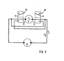
- a fluid circuit with pump 9 and hydraulic motor 13 and a switch valve arrangement 50 is shown again.
- the valve arrangement 50 essentially consists of two valves, which are represented schematically by sliders 51 and 52, which can be moved simultaneously from the position shown in the direction of arrow s. This creates the possibility of switching the flow of the hydraulic medium of the fluid circuit in the direction y in the illustrated position of the slides 51 and 52 in the direction z, which corresponds to the position of the slides 51 and 52 shifted in the direction s, with the delivery direction x of the pump 9 remaining the same assigned.
Landscapes
- Engineering & Computer Science (AREA)
- Mechanical Engineering (AREA)
- General Engineering & Computer Science (AREA)
- Chemical & Material Sciences (AREA)
- Combustion & Propulsion (AREA)
- Transportation (AREA)
- Structure Of Transmissions (AREA)
- Motor Power Transmission Devices (AREA)
- Valve Device For Special Equipments (AREA)
- Vehicle Body Suspensions (AREA)
- Vibration Prevention Devices (AREA)
Applications Claiming Priority (2)
| Application Number | Priority Date | Filing Date | Title |
|---|---|---|---|
| DE19833336590 DE3336590A1 (de) | 1983-10-07 | 1983-10-07 | Vorrichtung zum regelbaren antrieb grosser massen |
| DE3336590 | 1983-10-07 |
Publications (1)
| Publication Number | Publication Date |
|---|---|
| EP0137406A1 true EP0137406A1 (fr) | 1985-04-17 |
Family
ID=6211296
Family Applications (1)
| Application Number | Title | Priority Date | Filing Date |
|---|---|---|---|
| EP84111461A Withdrawn EP0137406A1 (fr) | 1983-10-07 | 1984-09-26 | Ensemble pour la propulsion réglable de masses importantes |
Country Status (3)
| Country | Link |
|---|---|
| EP (1) | EP0137406A1 (fr) |
| JP (1) | JPS60157559A (fr) |
| DE (1) | DE3336590A1 (fr) |
Cited By (11)
| Publication number | Priority date | Publication date | Assignee | Title |
|---|---|---|---|---|
| US4874057A (en) * | 1988-03-29 | 1989-10-17 | Smith Roger M | Hydromechanical all wheel drive |
| DE4404829A1 (de) * | 1994-02-16 | 1995-08-17 | Orenstein & Koppel Ag | Lastschaltgetriebe, insbesondere für mobile Bau- und Arbeitsmaschinen, sowie Verfahren zur Steuerung eines Lastschaltgetriebes |
| EP0794360A1 (fr) * | 1996-03-04 | 1997-09-10 | Mitsubishi Heavy Industries, Ltd. | Variateur de vitesse |
| EP0750136A3 (fr) * | 1995-06-23 | 1998-02-18 | Brueninghaus Hydromatik Gmbh | Entraínement de roue hydromécanique à train épicycloidal |
| DE10104420A1 (de) * | 2001-02-01 | 2002-08-08 | Zahnradfabrik Friedrichshafen | Synchrongetriebe |
| RU2247037C1 (ru) * | 2003-06-26 | 2005-02-27 | Южно-Уральский государственный университет | Гидрообъемная трансмиссия гусеничного трактора |
| US7608092B1 (en) | 2004-02-20 | 2009-10-27 | Biomet Sports Medicince, LLC | Method and apparatus for performing meniscus repair |
| AT512089A1 (de) * | 2012-03-28 | 2013-05-15 | Wacker Neuson Linz Gmbh | Fahrantrieb mit einem stufenlosen Getriebe |
| CN105370595A (zh) * | 2015-12-03 | 2016-03-02 | 安徽普伦智能装备有限公司 | 一种停歇式正反转风扇 |
| CN106740082A (zh) * | 2016-12-19 | 2017-05-31 | 长安大学 | 一种低速大扭矩输出的平地机行驶液压驱动装置 |
| CN111120614A (zh) * | 2020-03-09 | 2020-05-08 | 扬州维邦园林机械有限公司 | 机械液压式无级变速器及使用该变速器的车辆 |
Families Citing this family (7)
| Publication number | Priority date | Publication date | Assignee | Title |
|---|---|---|---|---|
| US4848186A (en) * | 1987-12-23 | 1989-07-18 | General Electric Company | Dual hydrostatic drive transmission |
| JPH07286653A (ja) * | 1994-04-18 | 1995-10-31 | Sumitomo Constr Mach Co Ltd | 油圧式駆動装置 |
| DE102004023631A1 (de) * | 2004-05-10 | 2005-12-08 | Zf Friedrichshafen Ag | Antrieb für Mobilfahrzeuge |
| US7082760B2 (en) | 2004-06-29 | 2006-08-01 | Zf Friedrichshafen Ag | Drive system for mobile vehicles |
| DE102007057534A1 (de) * | 2007-11-29 | 2009-06-04 | Hytrac Gmbh | Baukastensystem für ein hydrostatisch mechanisches Lastschaltgetriebe |
| CN108006190A (zh) * | 2018-01-10 | 2018-05-08 | 西安卓士博液压工程有限责任公司 | 一种大范围无极变速混合传动装置及方法 |
| CN114407645A (zh) * | 2022-01-03 | 2022-04-29 | 南昌智能新能源汽车研究院 | 一种采用惰轮传动的轮边减速驱动系统 |
Citations (4)
| Publication number | Priority date | Publication date | Assignee | Title |
|---|---|---|---|---|
| DE1918954A1 (de) * | 1969-04-15 | 1970-10-22 | Zahnradfabrik Friedrichshafen | Regelbares Planetengetriebe |
| DE2101515A1 (fr) * | 1971-01-14 | 1972-07-27 | ||
| DE2202615A1 (de) * | 1970-06-15 | 1973-08-02 | Cmi Corp | Hydrostatisches antriebssystem |
| GB1573836A (en) * | 1978-03-07 | 1980-08-28 | Renold Ltd | Drive systems employing hydraulic motors |
-
1983
- 1983-10-07 DE DE19833336590 patent/DE3336590A1/de not_active Withdrawn
-
1984
- 1984-09-26 EP EP84111461A patent/EP0137406A1/fr not_active Withdrawn
- 1984-10-08 JP JP20994084A patent/JPS60157559A/ja active Pending
Patent Citations (4)
| Publication number | Priority date | Publication date | Assignee | Title |
|---|---|---|---|---|
| DE1918954A1 (de) * | 1969-04-15 | 1970-10-22 | Zahnradfabrik Friedrichshafen | Regelbares Planetengetriebe |
| DE2202615A1 (de) * | 1970-06-15 | 1973-08-02 | Cmi Corp | Hydrostatisches antriebssystem |
| DE2101515A1 (fr) * | 1971-01-14 | 1972-07-27 | ||
| GB1573836A (en) * | 1978-03-07 | 1980-08-28 | Renold Ltd | Drive systems employing hydraulic motors |
Cited By (16)
| Publication number | Priority date | Publication date | Assignee | Title |
|---|---|---|---|---|
| US4874057A (en) * | 1988-03-29 | 1989-10-17 | Smith Roger M | Hydromechanical all wheel drive |
| DE4404829A1 (de) * | 1994-02-16 | 1995-08-17 | Orenstein & Koppel Ag | Lastschaltgetriebe, insbesondere für mobile Bau- und Arbeitsmaschinen, sowie Verfahren zur Steuerung eines Lastschaltgetriebes |
| EP0750136A3 (fr) * | 1995-06-23 | 1998-02-18 | Brueninghaus Hydromatik Gmbh | Entraínement de roue hydromécanique à train épicycloidal |
| EP0794360A1 (fr) * | 1996-03-04 | 1997-09-10 | Mitsubishi Heavy Industries, Ltd. | Variateur de vitesse |
| US5997426A (en) * | 1996-03-04 | 1999-12-07 | Mitsubishi Heavy Industries, Ltd. | Variable speed power transmission apparatus |
| CN1096581C (zh) * | 1996-03-04 | 2002-12-18 | 三菱重工业株式会社 | 可变速动力传递装置 |
| DE10104420A1 (de) * | 2001-02-01 | 2002-08-08 | Zahnradfabrik Friedrichshafen | Synchrongetriebe |
| EP1231413A2 (fr) | 2001-02-01 | 2002-08-14 | ZF FRIEDRICHSHAFEN Aktiengesellschaft | Transmission synchronisée |
| RU2247037C1 (ru) * | 2003-06-26 | 2005-02-27 | Южно-Уральский государственный университет | Гидрообъемная трансмиссия гусеничного трактора |
| US7608092B1 (en) | 2004-02-20 | 2009-10-27 | Biomet Sports Medicince, LLC | Method and apparatus for performing meniscus repair |
| AT512089A1 (de) * | 2012-03-28 | 2013-05-15 | Wacker Neuson Linz Gmbh | Fahrantrieb mit einem stufenlosen Getriebe |
| CN105370595A (zh) * | 2015-12-03 | 2016-03-02 | 安徽普伦智能装备有限公司 | 一种停歇式正反转风扇 |
| CN106740082A (zh) * | 2016-12-19 | 2017-05-31 | 长安大学 | 一种低速大扭矩输出的平地机行驶液压驱动装置 |
| CN106740082B (zh) * | 2016-12-19 | 2023-05-30 | 长安大学 | 一种低速大扭矩输出的平地机行驶液压驱动装置 |
| CN111120614A (zh) * | 2020-03-09 | 2020-05-08 | 扬州维邦园林机械有限公司 | 机械液压式无级变速器及使用该变速器的车辆 |
| CN111120614B (zh) * | 2020-03-09 | 2023-05-30 | 扬州维邦园林机械有限公司 | 机械液压式无级变速器及使用该变速器的车辆 |
Also Published As
| Publication number | Publication date |
|---|---|
| JPS60157559A (ja) | 1985-08-17 |
| DE3336590A1 (de) | 1985-05-09 |
Similar Documents
| Publication | Publication Date | Title |
|---|---|---|
| DE69402061T2 (de) | Stufenlos variabeles getriebe | |
| EP0137406A1 (fr) | Ensemble pour la propulsion réglable de masses importantes | |
| WO1982000270A1 (fr) | Groupe propulseur avec moteur d'entrainement et un volant | |
| DE4000667A1 (de) | Kraftuebertragungseinrichtung fuer ein motorfahrzeug mit vierradantrieb | |
| EP0561430B1 (fr) | Transmission hydrostatique pour composants à plusieurs ponts moteurs ainsi que procédé pour l'entraînement hydrostatique desdits composants | |
| DE2525888B2 (de) | Leistungsverzweigende Getriebeanordnung | |
| EP0528319B1 (fr) | Transmission pour véhicules avec différentiel central | |
| EP0389500B1 (fr) | Boite de direction superposee pour vehicules a chenilles | |
| DE3854813T2 (de) | Doppel-hydrostatisches Getriebe | |
| DE102022204749B4 (de) | Achssystem, Antriebssystem und Fahrzeug | |
| EP1855934B1 (fr) | Systeme d'entrainement destine a l'entrainement individuel des deux roues motrices d'une paire de roues motrices | |
| DE2844116C2 (de) | Hydromechanisches Überlagerungslenkgetriebe | |
| DE69609450T2 (de) | Stufenloses Toroidgetriebe für vierradgetriebene Kraftfahrzeuge | |
| EP0347594B1 (fr) | Transmission pour véhicules automobiles | |
| DE2409914C2 (fr) | ||
| DE19736549A1 (de) | Extruder-Antriebsvorrichtung für Doppelschneckenextruder | |
| CH395757A (de) | Stufenlos regelbares hydrostatisch-mechanisches Getriebe, insbesondere für Fahrzeuge | |
| DE7831817U1 (de) | Steuerungsmechanismus fuer einen kraftuebertragungsmechanismus mit zwei abtriebswellen | |
| DE3707382A1 (de) | Hydrostatisch-mechanischer radantrieb | |
| EP0143210A1 (fr) | Agencement de boîte de vitesse pour bateaux | |
| WO1990002893A1 (fr) | Transmission hydromecanique a variation continue avec repartition de puissance, notamment pour vehicules a moteur | |
| DE2942775C2 (de) | Umlaufreibungsgetriebe | |
| DE4010764A1 (de) | Regelbares-dreiwellen-hygrostatisches- differential-planeten-getriebe | |
| DE19510914C2 (de) | Hydromechanisches Antriebsaggregat | |
| DE2424737C2 (de) | Fahrzeugantrieb mit veränderlicher Übersetzung |
Legal Events
| Date | Code | Title | Description |
|---|---|---|---|
| PUAI | Public reference made under article 153(3) epc to a published international application that has entered the european phase |
Free format text: ORIGINAL CODE: 0009012 |
|
| AK | Designated contracting states |
Designated state(s): DE FR GB IT |
|
| RTI1 | Title (correction) | ||
| STAA | Information on the status of an ep patent application or granted ep patent |
Free format text: STATUS: THE APPLICATION IS DEEMED TO BE WITHDRAWN |
|
| 18D | Application deemed to be withdrawn |
Effective date: 19851218 |
|
| RIN1 | Information on inventor provided before grant (corrected) |
Inventor name: PRECHTEL, GEORG |