EP0137477A2 - Support de moteur à amortissement hydraulique et comportant deux chambres - Google Patents
Support de moteur à amortissement hydraulique et comportant deux chambres Download PDFInfo
- Publication number
- EP0137477A2 EP0137477A2 EP84112001A EP84112001A EP0137477A2 EP 0137477 A2 EP0137477 A2 EP 0137477A2 EP 84112001 A EP84112001 A EP 84112001A EP 84112001 A EP84112001 A EP 84112001A EP 0137477 A2 EP0137477 A2 EP 0137477A2
- Authority
- EP
- European Patent Office
- Prior art keywords
- cavity
- engine mount
- chamber
- intermediate plate
- mount according
- Prior art date
- Legal status (The legal status is an assumption and is not a legal conclusion. Google has not performed a legal analysis and makes no representation as to the accuracy of the status listed.)
- Granted
Links
Images
Classifications
-
- F—MECHANICAL ENGINEERING; LIGHTING; HEATING; WEAPONS; BLASTING
- F16—ENGINEERING ELEMENTS AND UNITS; GENERAL MEASURES FOR PRODUCING AND MAINTAINING EFFECTIVE FUNCTIONING OF MACHINES OR INSTALLATIONS; THERMAL INSULATION IN GENERAL
- F16F—SPRINGS; SHOCK-ABSORBERS; MEANS FOR DAMPING VIBRATION
- F16F13/00—Units comprising springs of the non-fluid type as well as vibration-dampers, shock-absorbers, or fluid springs
- F16F13/04—Units comprising springs of the non-fluid type as well as vibration-dampers, shock-absorbers, or fluid springs comprising both a plastics spring and a damper, e.g. a friction damper
- F16F13/06—Units comprising springs of the non-fluid type as well as vibration-dampers, shock-absorbers, or fluid springs comprising both a plastics spring and a damper, e.g. a friction damper the damper being a fluid damper, e.g. the plastics spring not forming a part of the wall of the fluid chamber of the damper
- F16F13/08—Units comprising springs of the non-fluid type as well as vibration-dampers, shock-absorbers, or fluid springs comprising both a plastics spring and a damper, e.g. a friction damper the damper being a fluid damper, e.g. the plastics spring not forming a part of the wall of the fluid chamber of the damper the plastics spring forming at least a part of the wall of the fluid chamber of the damper
- F16F13/10—Units comprising springs of the non-fluid type as well as vibration-dampers, shock-absorbers, or fluid springs comprising both a plastics spring and a damper, e.g. a friction damper the damper being a fluid damper, e.g. the plastics spring not forming a part of the wall of the fluid chamber of the damper the plastics spring forming at least a part of the wall of the fluid chamber of the damper the wall being at least in part formed by a flexible membrane or the like
- F16F13/105—Units comprising springs of the non-fluid type as well as vibration-dampers, shock-absorbers, or fluid springs comprising both a plastics spring and a damper, e.g. a friction damper the damper being a fluid damper, e.g. the plastics spring not forming a part of the wall of the fluid chamber of the damper the plastics spring forming at least a part of the wall of the fluid chamber of the damper the wall being at least in part formed by a flexible membrane or the like characterised by features of partitions between two working chambers
- F16F13/107—Passage design between working chambers
Definitions
- the invention relates to a two-chamber engine mount with hydraulic damping, in particular for motor vehicles, the chambers of which are filled with liquid and have rubber-elastic peripheral walls are connected to one another via a line provided in an intermediate plate.
- Such an engine mount is known for example from DE-OS 30 19 337.
- a wenda-shaped channel is provided in the intermediate plate, the ratio of length to diameter of which should be greater than 4, since only from such a ratio does a laminar flow occur in a channel with a circular cross section.
- the advantage of such a long channel - in contrast to the previously only throttle openings in the intermediate plate - is that the liquid column standing in the channel acts practically as an absorber mass and thus exerts an excellent damping effect on vibrations of large amplitude and low frequency. The greatest damping effect occurs when the liquid column trapped in the channel resonates with the excitation frequency.
- the invention is therefore based on the object of providing an engine mount whose damping capacity can be further optimized and adapted to the respective requirements with simple means.
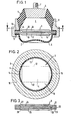
- the invention provides that the intermediate plate has an elongated cavity in the region of its central plane which is approximately rectangular in longitudinal section, the length and width of which is a multiple of its height, and which has a vertical passage at one end the upper chamber and through a corresponding passage at the other end with the lower chamber.
- the cavity itself can be rectangular or approximately oval or circular when viewed from above.
- the intermediate plate is divided in its horizontal central plane and each plate half has corresponding congruent recesses in its parting plane for the formation of the cavity and one passage each.
- the passages can be slit-shaped and extend over the entire width of the cavity.
- the passages can also have a cross-sectional cross-section when viewed from above and connect with their circular-arc-shaped side directly to the inner circumference of the bearing chambers.
- the engine mount essentially consists of an upper engine-side chamber 1 and a lower chamber 2, which are hydraulically connected to one another by a line running in the intermediate plate 3 to be described and designed as a cavity 4.
- the upper chamber 1 is formed by a thick-walled, hollow-conical chamber wall 5 made of a rubber-elastic material, which is adhesively connected on the upper end face by a motor-side bearing plate 6 with a retaining bolt 7 and in the lower region with the retaining flange 8 for connection to an abutment (not shown) is.
- the lower chamber 2 is formed by a cup-shaped chamber wall 9, for example, which is likewise made of rubber-elastic but softer material and is adhesively connected to the flange 8.
- Both chambers 1 and 2 are filled with a hydraulic fluid, generally a mixture of glycol and water.
- the intermediate plate 3 is elastically supported in its peripheral area within the retaining flange 8 by the rubber linings 10 and 11 drawn in, so that it is subjected to vibrations excited by the motor to be supported high frequency and small amplitude can resonate without a liquid exchange between the two chambers 1 and 2 takes place. This makes a good acoustic. Insulation ensures that structure-borne noise transmission from the engine to the vehicle body is largely prevented.
- the cavity 4 is a vertical and slot-shaped passage 14 with the upper Chamber 1 and a corresponding passage 15 with the lower chamber 2 in connection.
- These passages 14 and 15 are expediently arranged on the outer region of the cavity 4, so that as large a volume of liquid as possible is enclosed between them and, according to the illustrated embodiment, can have a circular cross-section and connect directly to the inner contour of the chambers 1 and 2.
- the intermediate plate 3 is divided in its horizontal central plane into an upper plate half 16 and a lower plate half 17, with each plate half 16 and 17 in its parting plane corresponding corresponding recesses 18 and 19 respectively to form the cavity 4 in the assembled state.
- the upper passage 14 is cut into the upper plate half 16 and the lower passage 15 into the lower plate half 17.
- the connecting line By designing the connecting line as a flat hollow chamber, a considerably larger mass of liquid can be stored than the previously customary channels with a circular cross-section with the same flow resistance.
- the volume of the cavity can vary within very wide limits by increasing the surface area and / or the height, so that the damping can be optimized and tuned to the corresponding frequencies within wide limits.
- the intermediate plate is composed of three individual plates 21, 22 and 23, being between the Plates 21 and 22 of the partial cavity 24 and between the plates 22 and 23 of the partial cavity 25 is formed by corresponding recesses in the plates.
- the two partial cavities 24 and 25 are at one end via the channel 26 passing through the middle plate 22 and at the other end via the passage 27 in the upper plate 21 with the storage chamber 1 and via the passage 28 in the lower plate 23 with the storage chamber 2 in connection.
Landscapes
- Engineering & Computer Science (AREA)
- General Engineering & Computer Science (AREA)
- Mechanical Engineering (AREA)
- Combined Devices Of Dampers And Springs (AREA)
- Fluid-Damping Devices (AREA)
- Vehicle Body Suspensions (AREA)
- Transition And Organic Metals Composition Catalysts For Addition Polymerization (AREA)
- Valve Device For Special Equipments (AREA)
- Lubrication Of Internal Combustion Engines (AREA)
- Arrangement Or Mounting Of Propulsion Units For Vehicles (AREA)
- Vibration Prevention Devices (AREA)
Priority Applications (1)
| Application Number | Priority Date | Filing Date | Title |
|---|---|---|---|
| AT84112001T ATE32371T1 (de) | 1983-10-11 | 1984-10-06 | Zweikammer-motorlager mit hydraulischer daempfung. |
Applications Claiming Priority (2)
| Application Number | Priority Date | Filing Date | Title |
|---|---|---|---|
| DE3336966 | 1983-10-11 | ||
| DE3336966A DE3336966C2 (de) | 1983-10-11 | 1983-10-11 | Zweikammer-Motorlager mit hydraulischer Dämpfung |
Publications (3)
| Publication Number | Publication Date |
|---|---|
| EP0137477A2 true EP0137477A2 (fr) | 1985-04-17 |
| EP0137477A3 EP0137477A3 (en) | 1986-06-25 |
| EP0137477B1 EP0137477B1 (fr) | 1988-02-03 |
Family
ID=6211553
Family Applications (1)
| Application Number | Title | Priority Date | Filing Date |
|---|---|---|---|
| EP84112001A Expired EP0137477B1 (fr) | 1983-10-11 | 1984-10-06 | Support de moteur à amortissement hydraulique et comportant deux chambres |
Country Status (9)
| Country | Link |
|---|---|
| US (1) | US4618128A (fr) |
| EP (1) | EP0137477B1 (fr) |
| JP (1) | JPS60104827A (fr) |
| AT (1) | ATE32371T1 (fr) |
| AU (1) | AU563053B2 (fr) |
| BR (1) | BR8405104A (fr) |
| DE (2) | DE3336966C2 (fr) |
| ES (1) | ES281619Y (fr) |
| ZA (1) | ZA847933B (fr) |
Cited By (5)
| Publication number | Priority date | Publication date | Assignee | Title |
|---|---|---|---|---|
| EP0278054A1 (fr) * | 1987-02-07 | 1988-08-17 | Boge A.G. | Support en caoutchouc à amortissement hydraulique |
| EP0271848A3 (en) * | 1986-12-16 | 1989-01-04 | Metzeler Gesellschaft Mit Beschrankter Haftung | Active hydraulically damping motor mount |
| EP0312719A1 (fr) * | 1987-10-21 | 1989-04-26 | Firma Carl Freudenberg | Palier en caoutchouc |
| EP3006770A4 (fr) * | 2013-06-03 | 2016-06-22 | Bridgestone Corp | Dispositif d'amortissement des vibrations |
| US10030738B2 (en) | 2014-02-17 | 2018-07-24 | Bridgestone Corporation | Vibration-damping device |
Families Citing this family (11)
| Publication number | Priority date | Publication date | Assignee | Title |
|---|---|---|---|---|
| JPS60184737A (ja) * | 1984-02-21 | 1985-09-20 | Honda Motor Co Ltd | 流体入りマウント |
| FR2575253B1 (fr) * | 1984-12-24 | 1989-08-18 | Hutchinson | Support antivibratoire hydraulique |
| CA1250824A (fr) * | 1985-02-28 | 1989-03-07 | General Motors Corporation | Monture hydraulique-elastomere |
| DE3526607A1 (de) * | 1985-07-25 | 1987-01-29 | Continental Gummi Werke Ag | Hydraulisch gedaempftes elastisches lager |
| DE3629860A1 (de) * | 1986-09-02 | 1988-03-10 | Metzeler Kautschuk | Lager mit hydraulischer daempfung |
| FR2613445B1 (fr) * | 1987-04-03 | 1991-07-05 | Caoutchouc Manuf Plastique | Support elastique a amortissement hydraulique integre avec cloison rigide a circuit de liquide ajustable |
| DE3744916C2 (en) * | 1987-10-21 | 1992-03-05 | Fa. Carl Freudenberg, 6940 Weinheim, De | IC engine rubber mounting with hydraulic fluid |
| JPH01312242A (ja) * | 1988-06-13 | 1989-12-18 | Nissan Motor Co Ltd | 粘度可変流体封入制御型防振体 |
| JP6196681B2 (ja) * | 2013-11-11 | 2017-09-13 | 株式会社ブリヂストン | 防振装置 |
| JP6335622B2 (ja) * | 2014-04-30 | 2018-05-30 | 株式会社ブリヂストン | 防振装置 |
| US10145443B2 (en) | 2015-01-26 | 2018-12-04 | Itt Manufacturing Enterprises Llc | Compliant elastomeric shock absorbing apparatus |
Family Cites Families (6)
| Publication number | Priority date | Publication date | Assignee | Title |
|---|---|---|---|---|
| US2535080A (en) * | 1945-06-07 | 1950-12-26 | Norman E Lee | Mounting |
| DE2905091C2 (de) * | 1979-02-10 | 1981-10-01 | Fa. Carl Freudenberg, 6940 Weinheim | Gummilager mit hydraulischer Dämpfung |
| DE2950888A1 (de) * | 1979-12-18 | 1981-06-25 | Stabilus Gmbh | Daempfkolben fuer pneumatische, hydraulische und hydropneumatische aggregate |
| DE3019337C2 (de) * | 1980-05-21 | 1986-07-31 | Fa. Carl Freudenberg, 6940 Weinheim | Elastisches Gummilager |
| US4483521A (en) * | 1981-07-01 | 1984-11-20 | Nissan Motor Company, Limited | Rubber and fluid type vibration damper |
| EP0115417B1 (fr) * | 1983-01-25 | 1989-04-19 | Avon Industrial Polymers Limited | Dispositif de montage à amortissement hydraulique |
-
1983
- 1983-10-11 DE DE3336966A patent/DE3336966C2/de not_active Expired
-
1984
- 1984-09-12 AU AU32952/84A patent/AU563053B2/en not_active Ceased
- 1984-09-27 ES ES1984281619U patent/ES281619Y/es not_active Expired
- 1984-10-06 AT AT84112001T patent/ATE32371T1/de not_active IP Right Cessation
- 1984-10-06 EP EP84112001A patent/EP0137477B1/fr not_active Expired
- 1984-10-06 DE DE8484112001T patent/DE3469211D1/de not_active Expired
- 1984-10-08 JP JP59211196A patent/JPS60104827A/ja active Pending
- 1984-10-10 BR BR8405104A patent/BR8405104A/pt unknown
- 1984-10-11 ZA ZA847933A patent/ZA847933B/xx unknown
- 1984-10-11 US US06/659,708 patent/US4618128A/en not_active Expired - Fee Related
Cited By (6)
| Publication number | Priority date | Publication date | Assignee | Title |
|---|---|---|---|---|
| EP0271848A3 (en) * | 1986-12-16 | 1989-01-04 | Metzeler Gesellschaft Mit Beschrankter Haftung | Active hydraulically damping motor mount |
| EP0278054A1 (fr) * | 1987-02-07 | 1988-08-17 | Boge A.G. | Support en caoutchouc à amortissement hydraulique |
| EP0312719A1 (fr) * | 1987-10-21 | 1989-04-26 | Firma Carl Freudenberg | Palier en caoutchouc |
| EP3006770A4 (fr) * | 2013-06-03 | 2016-06-22 | Bridgestone Corp | Dispositif d'amortissement des vibrations |
| US10221916B2 (en) | 2013-06-03 | 2019-03-05 | Bridgestone Corporation | Anti-vibration apparatus |
| US10030738B2 (en) | 2014-02-17 | 2018-07-24 | Bridgestone Corporation | Vibration-damping device |
Also Published As
| Publication number | Publication date |
|---|---|
| EP0137477B1 (fr) | 1988-02-03 |
| US4618128A (en) | 1986-10-21 |
| ZA847933B (en) | 1985-08-28 |
| BR8405104A (pt) | 1985-08-27 |
| ATE32371T1 (de) | 1988-02-15 |
| AU3295284A (en) | 1985-04-18 |
| JPS60104827A (ja) | 1985-06-10 |
| AU563053B2 (en) | 1987-06-25 |
| EP0137477A3 (en) | 1986-06-25 |
| DE3469211D1 (en) | 1988-03-10 |
| DE3336966C2 (de) | 1986-11-06 |
| DE3336966A1 (de) | 1985-05-02 |
| ES281619Y (es) | 1985-10-01 |
| ES281619U (es) | 1985-02-16 |
Similar Documents
| Publication | Publication Date | Title |
|---|---|---|
| EP0137477B1 (fr) | Support de moteur à amortissement hydraulique et comportant deux chambres | |
| EP0150824B1 (fr) | Support de moteur à deux chambres d'amortissement hydraulique | |
| DE19843558B4 (de) | Hydraulisch dämpfendes Gummilager | |
| EP0137112B1 (fr) | Support de moteur à amortissement hydraulique et comportant deux chambres | |
| EP0098330B1 (fr) | Support élastique en caoutchouc | |
| EP0209883B1 (fr) | Support de moteur à amortissement hydraulique et à deux chambres | |
| DE3416431C2 (de) | Hydraulisch dämpfendes Gummilager | |
| DE3927715C2 (de) | Elastische Aufhängung mit einer Fluidfüllung | |
| DE3330462C2 (de) | Hydraulisch bedämpftes Motorlager | |
| DE3535906C2 (fr) | ||
| EP0534124B1 (fr) | Support moteur élastique | |
| EP0044545A2 (fr) | Support de moteur à deux chambres d'amortissement hydraulique | |
| DE68909208T2 (de) | Abgedichtete, mit flüssigkeit gefüllte lagervorrichtung. | |
| DE3632670A1 (de) | Hydraulisch daempfendes gummilager | |
| DE2550124C2 (de) | Elektroakustischer Wandler für große Eintauchtiefe | |
| EP0611901A1 (fr) | Coussinet de palier à amortissement hydraulique | |
| DE3129631C2 (de) | Laschenkette für stufenlos verstellbare Kegelscheibengetriebe | |
| DE102009048449A1 (de) | Schaltbare Motorhalterung mit mehreren Zuständen und System | |
| DE3342300C2 (fr) | ||
| EP0231898B1 (fr) | Support à amortissement hydraulique | |
| EP0161554A2 (fr) | Support élastique en caoutchouc à amortissement hydraulique intégré | |
| DE3617813C2 (fr) | ||
| DE3730425C2 (fr) | ||
| DE3618767C2 (de) | Motorlager mit hydraulischer Dämpfung | |
| DE3930644C2 (fr) |
Legal Events
| Date | Code | Title | Description |
|---|---|---|---|
| PUAI | Public reference made under article 153(3) epc to a published international application that has entered the european phase |
Free format text: ORIGINAL CODE: 0009012 |
|
| 17P | Request for examination filed |
Effective date: 19841006 |
|
| AK | Designated contracting states |
Designated state(s): AT BE DE FR GB IT NL SE |
|
| RTI1 | Title (correction) | ||
| PUAL | Search report despatched |
Free format text: ORIGINAL CODE: 0009013 |
|
| AK | Designated contracting states |
Kind code of ref document: A3 Designated state(s): AT BE DE FR GB IT NL SE |
|
| 17Q | First examination report despatched |
Effective date: 19870722 |
|
| GRAA | (expected) grant |
Free format text: ORIGINAL CODE: 0009210 |
|
| AK | Designated contracting states |
Kind code of ref document: B1 Designated state(s): AT BE DE FR GB IT NL SE |
|
| REF | Corresponds to: |
Ref document number: 32371 Country of ref document: AT Date of ref document: 19880215 Kind code of ref document: T |
|
| ITF | It: translation for a ep patent filed | ||
| REF | Corresponds to: |
Ref document number: 3469211 Country of ref document: DE Date of ref document: 19880310 |
|
| ET | Fr: translation filed | ||
| GBT | Gb: translation of ep patent filed (gb section 77(6)(a)/1977) | ||
| REG | Reference to a national code |
Ref country code: FR Ref legal event code: CN |
|
| PLBE | No opposition filed within time limit |
Free format text: ORIGINAL CODE: 0009261 |
|
| STAA | Information on the status of an ep patent application or granted ep patent |
Free format text: STATUS: NO OPPOSITION FILED WITHIN TIME LIMIT |
|
| NLS | Nl: assignments of ep-patents |
Owner name: METZELER GESELLSCHAFT MIT BESCHRAENKTER HAFTUNG TE |
|
| ITPR | It: changes in ownership of a european patent |
Owner name: CAMBIO RAGIONE SOCIALE;METZELER GESELLSCHAFT MIT B |
|
| 26N | No opposition filed | ||
| REG | Reference to a national code |
Ref country code: FR Ref legal event code: CD |
|
| PGFP | Annual fee paid to national office [announced via postgrant information from national office to epo] |
Ref country code: SE Payment date: 19890823 Year of fee payment: 6 |
|
| PGFP | Annual fee paid to national office [announced via postgrant information from national office to epo] |
Ref country code: BE Payment date: 19891011 Year of fee payment: 6 Ref country code: AT Payment date: 19891011 Year of fee payment: 6 |
|
| PGFP | Annual fee paid to national office [announced via postgrant information from national office to epo] |
Ref country code: NL Payment date: 19891031 Year of fee payment: 6 |
|
| PG25 | Lapsed in a contracting state [announced via postgrant information from national office to epo] |
Ref country code: AT Effective date: 19901006 |
|
| PG25 | Lapsed in a contracting state [announced via postgrant information from national office to epo] |
Ref country code: SE Effective date: 19901007 |
|
| PG25 | Lapsed in a contracting state [announced via postgrant information from national office to epo] |
Ref country code: BE Effective date: 19901031 |
|
| BERE | Be: lapsed |
Owner name: METZELER KAUTSCHUK G.M.B.H. Effective date: 19901031 |
|
| PG25 | Lapsed in a contracting state [announced via postgrant information from national office to epo] |
Ref country code: NL Effective date: 19910501 |
|
| NLV4 | Nl: lapsed or anulled due to non-payment of the annual fee | ||
| ITTA | It: last paid annual fee | ||
| PGFP | Annual fee paid to national office [announced via postgrant information from national office to epo] |
Ref country code: FR Payment date: 19921030 Year of fee payment: 9 |
|
| PGFP | Annual fee paid to national office [announced via postgrant information from national office to epo] |
Ref country code: GB Payment date: 19921102 Year of fee payment: 9 |
|
| PGFP | Annual fee paid to national office [announced via postgrant information from national office to epo] |
Ref country code: DE Payment date: 19921110 Year of fee payment: 9 |
|
| ITPR | It: changes in ownership of a european patent |
Owner name: CAMBIO RAGIONE SOCIALE;METZELER AUTOMOTIVE PROFILE |
|
| ITPR | It: changes in ownership of a european patent |
Owner name: CESSIONE;METZELER GIMETALL AG |
|
| REG | Reference to a national code |
Ref country code: GB Ref legal event code: 732E |
|
| REG | Reference to a national code |
Ref country code: FR Ref legal event code: TP Ref country code: FR Ref legal event code: CD Ref country code: FR Ref legal event code: CA |
|
| PG25 | Lapsed in a contracting state [announced via postgrant information from national office to epo] |
Ref country code: GB Effective date: 19931006 |
|
| GBPC | Gb: european patent ceased through non-payment of renewal fee |
Effective date: 19931006 |
|
| PG25 | Lapsed in a contracting state [announced via postgrant information from national office to epo] |
Ref country code: FR Effective date: 19940630 |
|
| PG25 | Lapsed in a contracting state [announced via postgrant information from national office to epo] |
Ref country code: DE Effective date: 19940701 |
|
| REG | Reference to a national code |
Ref country code: FR Ref legal event code: ST |
|
| EUG | Se: european patent has lapsed |
Ref document number: 84112001.7 Effective date: 19910603 |