EP0137629A2 - Apparat zum Fördern von Pappen von einer Leimauftragevorrichtung zu einer Pappenzuführvorrichtung - Google Patents
Apparat zum Fördern von Pappen von einer Leimauftragevorrichtung zu einer Pappenzuführvorrichtung Download PDFInfo
- Publication number
- EP0137629A2 EP0137629A2 EP84305447A EP84305447A EP0137629A2 EP 0137629 A2 EP0137629 A2 EP 0137629A2 EP 84305447 A EP84305447 A EP 84305447A EP 84305447 A EP84305447 A EP 84305447A EP 0137629 A2 EP0137629 A2 EP 0137629A2
- Authority
- EP
- European Patent Office
- Prior art keywords
- cartons
- feeder
- magazine
- conveyor
- gluer
- Prior art date
- Legal status (The legal status is an assumption and is not a legal conclusion. Google has not performed a legal analysis and makes no representation as to the accuracy of the status listed.)
- Granted
Links
Images



Classifications
-
- B—PERFORMING OPERATIONS; TRANSPORTING
- B31—MAKING ARTICLES OF PAPER, CARDBOARD OR MATERIAL WORKED IN A MANNER ANALOGOUS TO PAPER; WORKING PAPER, CARDBOARD OR MATERIAL WORKED IN A MANNER ANALOGOUS TO PAPER
- B31B—MAKING CONTAINERS OF PAPER, CARDBOARD OR MATERIAL WORKED IN A MANNER ANALOGOUS TO PAPER
- B31B50/00—Making rigid or semi-rigid containers, e.g. boxes or cartons
-
- B—PERFORMING OPERATIONS; TRANSPORTING
- B31—MAKING ARTICLES OF PAPER, CARDBOARD OR MATERIAL WORKED IN A MANNER ANALOGOUS TO PAPER; WORKING PAPER, CARDBOARD OR MATERIAL WORKED IN A MANNER ANALOGOUS TO PAPER
- B31B—MAKING CONTAINERS OF PAPER, CARDBOARD OR MATERIAL WORKED IN A MANNER ANALOGOUS TO PAPER
- B31B50/00—Making rigid or semi-rigid containers, e.g. boxes or cartons
- B31B50/74—Auxiliary operations
- B31B50/92—Delivering
- B31B50/98—Delivering in stacks or bundles
Definitions
- This invention relates to a cartoner for use with a side seam gluer and more particularly to a device for accumulating an excess capacity of flat folded cartons so as to keep the cartoner operating in the event of a jam in the side seam gluer.
- a cartoner generally has a transport conveyor into which erected tubular cartons are fed.
- a product bucket conveyor runs alongside the transport conveyor and carries product to be thrust into the open end of each cartoner.
- a side seam gluer which is a device for receiving a flat blank and folding and sealing it into a flat tubular carton. It is of course possible to have the cartons folded and sealed outside the cartoning plant and shipped into the cartoning plant in containers which are unloaded by the operator and placed in the cartoner magazine. This adds to the cost of the carton and requires substantially greater storage space adjacent the cartoning apparatus than do the unfolded carton blanks. It is therefore desirable to employ a side seam gluer, particularly with large cartons such as those suitable for breakfast cereals, and to feed cartons formed by it to the cartoner in such a way as to minimize cartoner down time.
- One way of eliminating some cartoner down time is to provide excess capacity of cartons at the carton feeder.
- the excess capacity permits the cartoner to be run for about two minutes in the event of jam in the side seam g luer. The two minutes should provide ample time for an operator to clear the jam. Thus, there is no cartoner down time arising out of a jam in the side seam gluer.
- an apparatus for conveying flat folded cartons from a side seam gluer to a carton feeder comprises an overhead conveyor for conveying cartons, a downwardly-directed discharge chute at the end of the conveyor, a generally horizontal magazine below the discharge chute and adjacent the feeder, the magazine including an endless conveyor for carrying generally vertically-oriented blanks to the feeder, means for moving the chute toward and away from the feeder as the number of blanks in the magazine diminishes and increases, respectively.
- a cartoner has a feeder for'flat folded cartons at one end and a side seam gluer located at the other end to form folded cartons, an overhead conveyor extending from the gluer to a location near the feeder, an inner and an outer endless belt having a substantially coextensive arcuate run and located adjacent the overhead conveyor to receive cartons and pass them through the arcuate run section, the arcuate run section having a discharge end adjacent the feeder, and means for moving the arcuate run section toward and away from the feeder to follow the contracting and expanding supply of cartons in the feeder.
- Such apparatus between the side seam gluer and the cartoner will automatically accumulate flat folded cartons upstream of the carton feeder, the accumulated cartons being available to keep the cartoner running for a few minutes when the side seam gluer jams.
- this is attained in part by providing the horizontally-movable discharge chute which receives flat folded carton blanks from the gluer and deposits them in a vertical orientation on the cartoner magazine.
- the chute is provided with a sensing mechanism which monitors the contraction or expansion of the supply of cartons and causes the end of the discharge chute to move in one direction if the supply is expanding and in the opposite direction if the supply is contracting.
- microswitches are provided on the frame which supports the discharge chute.
- the most remote microswitch is engaged by the discharge chute when the magazine is full. It operates to shut off the side seam gluer as well as all of the conveyor mechanism.
- the middle microswitch spaced approximately six inches from the remote microswitch, operates to start the side seam gluer.
- the third microswitch located about eighteen inches from the niddle microswitch, is engaged by the discharge chute when the supply of cartons in the magazine is almost depleted and operates to stop the cartoner. That eighteen to twenty-four inches of cartons should be sufficient to run the cartoner for about two minutes in the event of a jam in the gluer.
- the cartoner shown in Figures 1 to 3 includes a frame 10 which supports the principal operating elements.
- the frame supports a carton feeder 11, a carton transport conveyor 12, a product bucket conveyor 13 and product buckets 14 mounted on the conveyor and a barrel loader 15.
- An overhead tamper confiner 16 is employed for products which must be compressed either vertically or horizontally or both in order to size them for introduction into the cartoner.
- the cartoner is surrounded by a series of lower opaque guard panels 20 and guard windows 21 which are capable of being raised and lowered to expose the operating components of the machine for repairs, unclogging jams and the like.
- the feeder 11 has a frame 23 which supports a rotatable feed mechanism 24 of the type disclosed in EP-A-0068798.
- the feeder also includes a pair of spaced parallel upstream chains 25 on which flat folded cartons 26 are supported and gradually moved toward the rotary feeding device.
- the cartons 26 are fed onto the chains 25, as shown, by an overhead conveyor 66 which receives the cartons from a side seam gluer 65.
- the carton transport conveyor 12 has three elongated, parallel endless chains 29.
- the outboard chains support trailing transport lugs 30.
- the center chain 31 supports a leading transport lug 32.
- the center chain may be shifted with respect to the outboard chains in order to vary the spacing between the leading and trailing transport lugs in order to accommodate cartons of differing lengths (the length of the carton is the dimension in the machine direction).
- the cartons are fed in the flat folded condition onto the transport conveyor. Prior to being captured between the leading and trailing transport lugs of the conveyor 12, the carton is transported from the feeder by a conveyor 33.
- the carton flaps are separated by a flap separator 35 which forces a lower flap downwardly , into a position where it can be engaged by a stationary plough and turned and held at a 90° angle to the wall to which it is connected.
- the carton then moves through an air opener 36 which directs blasts of air from either side of the carton in a horizontal direction to force air between the upper and lower walls of the carton, thereby causing the carton to swing to an erect orientation between the leading and trailing lugs of the transport conveyor. That air opener is disclosed in U.S.-A-3,728,945.
- flap spreaders 40 Immediately downstream of the air opener are opposed flap spreaders 40.
- the flap spreaders carry lugs 41 which engage the leading flap of the carton and swing it through 90° so that it can be captured by stationary rails and held in that attitude as the carton passes the barrel loader 15.
- the trailing flap is similarly captured by the rails and held open.
- pusher heads 42 engage products in the product buckets and thrust them across the product buckets into the opened cartons.
- flap closers 43 which engage the trailing flaps and swing them to a closed position.
- Glue guns 44 are mounted alongside the carton conveyor 5 downstream of the flap closers 43.
- the glue guns apply an appropriate pattern of glue to one of the horizontal flaps of the carton. When the glue is applied, ploughs swing the horizontal flaps to a closed position and hold them there during the brief period required for the glue to set.
- the product bucket conveyor 13 consists of a pair of endless chains which support a series of spaced product buckets 14 which convey products 48 past the open cartons.
- the product buckets may be L-shaped as shown,, or may be U-shaped depending upon the product to be filled into the carton and the need for imparting shaping to the product to enable it to conform dimensionally to the size of the carton.
- the barrel loader 15 diagrammatically illustrated in Fig. 3 consists of a series of pusher heads 42 which are slidably supported on endless chains.
- the pusher heads have cam followers which ride in a cam track 52. As the pusher heads are conveyed on the upper run of the chains which support them, the cam track 52 causes each pusher head to move across the product bucket where it engages the product 48 and thrusts it into an open carton.
- the tamper confiner 16 has a series of L-shaped tamper confiner elements 60 which are carried by vertical posts 61 and supported on carriages 62.
- the carriages are connected to endless chains 63 mounted on horizontal sprockets, not shown, to convey the tamper confiner elements over the upper run of the product bucket conveyor adjacent the barrel loader.
- a cam track 64 is mounted adjacent the path of the posts 61.
- the posts 61 have followers which ride in the cam track to lower the tamper confiners as they pass over the product buckets and to raise them after the carton has been filled with product by the barrel loader so that they can be swung out of the way of the mechanism during their excursion around to the outside of the cartoner.
- the L-shaped tamper confiner elements cooperate with the L-shaped product buckets to engage the product such as a breakfast cereal pouch and to shape it into a generally rectangular cross section matching that of the interior of the carton, thereby enabling the pusher heads 42 to thrust the pouch into the cartons.
- the product buckets are U-shaped, the tamper confiner may be a flat platen which simply compresses the product as, for example, facial tissues, so that vertical dimension of the product matches the dimension of the carton opening.
- the cartoner has a side seam gluer 65 which feeds flat folded cartons in shingled fashion on a conveyor 66.
- the apparatus 67 At the downstream end of the conveyor 66 is the apparatus 67 for accumulating cartons on the feeder chains 25.
- the side seam gluer forms the flat folded cartons which are conveyed to the feeder 11.
- the cartons are fed from the feed mechanism 24 toward the transport conveyor.
- the upper and lower flaps of the carton are separated so as to permit air to be introduced between the upper and lower walls of the carton.
- At the air opener 36 blasts of air erect the carton between the leading and trailing transport lugs.
- the horizontal flaps are plowed up and down and the vertical flaps are swung through 90° on both sides of the carton to prepare the carton for the introduction of product.
- the carton flaps After the product has been loaded into the cartons, the carton flaps have a pattern of glue applied to them and are closed and held in a closed condition until the glue sets.
- the elongated overhead conveyor 66 between the side seam gluer 65 and the accumulating apparatus 67 permits the side seam gluer to be located on either side of the cartoning apparatus and at a location where it is least likely to intrude upon the machine operator.
- the machine operator normally stands at the upstream end of the machine in the position to attend the auxiliary apparatus such as a form, fill, seal machine for packaging breakfast cereals.
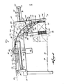
- the overhead accumulating apparatus is best shown in Figs. 4 and 5. It includes a main frame 70 on which a discharge conveyor 71 is movably mounted.
- the main frame has a screw 75 rotatably mounted in three bearing blocks 76, 77 and 78.
- a pair of rotary to linear actuators 79 and 80 engage the screw 75 and as the screw 75 is rotated, the actuators translate the rotary motion of the screw into linear motion of the actuators.
- the actuators are fixedly mounted to a support 82 which includes two walls 82a forming a frame for the discharge conveyor 71. Thus, as the actuators are caused to move linearly, they will carry the support 82 linearly.
- the screw 75 is connected to a variable speed reversible dc motor 83 through a gear box 84.
- the control for the motor 83 depends upon the number of cartons in the magazine, whether the cartoner is running, and whether the side seam gluer is running.
- the discharge conveyor 71 has a pair of belts which are spaced apart by the thickness of the cartons passing between them in the arcuate operative section of the discharge conveyor.
- An inner drive belt 85 passes around a drive roll 86 and idler rolls 87, 88, 89 and 90.
- Still another idler roll 91 is mounted adjacent the drive roll to increase the wrap of the belt around the drive roll.
- the idler roll 90 is mounted between a pair of arms 92 which are fixed to the movable support 82.
- Idler roll 87 is fixed to the fixed frame 70 as is the drive roll 86 and the idler roll 91.
- Idler rolls 88 and 89 are rotatably mounted between the movable support walls 82a.
- the belt 85 has an arcuate run at 94 which is supported by a sheet of material such as plastic 95, the sheet of material resting on cross members 96 mounted between the movable frame members 82a.
- the discharge conveyor also includes an outer idler or hold-down belt 98 which also has an arcuate run 99 overlying the arcuate run 94 of the drive belt 85.
- the idler belt is supported on idler pulleys 100, 101, 102, 103 and 104.
- the idler pulley 104 is preferably located as close as possible to the feed conveyor 25 for the magazine so as to maintain as good a control as possible over the cartons being fed into the magazine.
- the drive belt 85 is driven by a drive motor 110 through a gear box 111.
- the motor 110 will operate when the side seam gluer operates, the side seam gluer being the apparatus which feeds flat folded cartons to the drive belt 85 via overhead conveyor 66.
- the discharge conveyor is adapted to handle cartons of different sizes. To this end, it is important to be able to adjust the height of the idler roller 88 above the magazine conveyor 25 so that the lower extremity of the drive belt 85 is located immediately above the top edges of the cartons in the magazine.
- the idler roller 88 is therefore mounted between a pair of arms 115 which are both slidable in the directions of the arrow 116 and are capable of a slight pivotal movement about an axis 117.
- the bars 115 are retained in a C-shaped extrusion as shown in F ig. 6.
- the extrusion has two set screws 118 and 119.
- the extrusion is pivotally mounted to the movable support 82 about the set screw 119 which provides the pivotal action of the extrusion.
- the support 82 has an arcuate slot 120 through which the set screw 118 passes.
- the arcuate slot 120 permits the extrusion to swing through a small arc about the pivot axis 119.
- Adjustment of the position of the idler roll 88 is made by loosening the two set screws and sliding bars 115 and the roll 88 either up or down depending upon the size of the carton to be accommodated. As the bars are slid, the extrusion is pivoted slightly in order to keep the idler roll 88 adjacent to the idler belt 98. When in the desired position, the set.screws are tightened and the assembly will remain fixed in that attitude until another change is required.
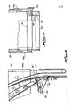
- the lower idler roll 104 is mounted between a pair of depending arms 125, the arms being pivoted at their upper ends at 126 to the movable support 82.
- the arms 125 have an upper extension 128.
- a tension spring 129 is connected between the upper extension 128 and the support 82 to urge the rollers 104 in a clockwise direction as viewed in Fig. 7.
- An adjustable block 130 is mounted on the upper extension of ) the arms and is engageable with the actuator of a nicroswitch 131. The tension spring urges the lower roller 104 against the stack of cartons in the magazine.
- the function of the microswitch 131 is to provide assurance that the roller 104 is in contact with the supply of cartons in the magazine and that contact is maintained at the desired pressure by the operation of the motor 83 which causes the support 82 to move in one direction or the other. For example, if the side seam gluer has stopped and no fresh cartons are being delivered down the discharge conveyor 71, the continued operation of the cartoner will deplete the cartons in the magazine. Hence, the tension spring will cause the arms to pivot in a clockwise direction pulling the block 130 away from the microswitch 131. Thus, when the microswitch is disengaged from the block 130, the microswitch will cause the motor to rotate in that direction which will cause the carriage to move in the direction of the feeder or toward the left as viewed in Figs. 4 and 5.
- the side seam gluer when the side seam gluer is operating, it will feed cartons into the magazine faster than the cartoner will use the cartons.
- the pressure of the incoming cartons on the arms 125 will cause them to swing in a counterclockwise direction as viewed in Fig. 7 and cause the block 130 to engage the microswitch 131.
- the microswitch 131 When the microswitch 131 is engaged, it will in turn cause the motor 83 to rotate in that direction which will cause the discharge conveyor to move away from the feeder, that is, to the right as viewed in Figs. 4 and 5.
- the discharge conveyor 71 is additionally controlled by three switches 14'0, 141, and 142 which are engaged by the discharge conveyor as it moves in and out with respect to the feeder.
- the outboard or remote switch 140 is operative when engaged to turn off the side seam gluer 65 and the conveyor 66 from the side seam gluer to the discharge conveyor, the conveyor 66 being driven by the motor 110.
- the nearer switch 141 is operative when engaged to turn on the side seam gluer and the motor 110 for the conveyors.
- the two switches 140 and 141 control the normal operation of the discharge conveyor. For example, let it be assumed that the cartoner 11 is operating at a rate of 100 cartons per minute and that the side seam gluer is operating at a speed about 10% faster than the cartoner.
- limit switches 140 and 141 are spaced apart about six inches, and if ten cartons will occupy one inch of space on the feeder magazine, between the time the microswitch 141 is operated to turn on the side seam gluer and the time the switch 140 is operated to turn off the side seam gluer, approximately six hundred sixty cartons will be discharged onto the magazine with the cartoner using six hundred of them. The introduction of sixty cartons onto the magazine will cause limit switch 140 to operate to turn off the gluer. That will require about six minutes. After the side seam gluer is turned off, the cartoner will remove the cartons at the rate of 100 per minute so that in about 36 seconds the discharge conveyor would have moved toward the left far enough to engage the microswitch 141. Thus, during the normal operation of the apparatus, there would be the continuous actuation of switches 141 and 140 as described above.
- the folded cartons are conveyed to the apparatus 67 and discharged at the upstream end of the feeder. If it is assumed that the side seam gluer is running, the microswitch 141 will have been engaged and the support 82 will be moving toward the microswitch 140. Since the gluer is operating at a speed about 10% greater than the cartoner, the supply of cartons 26 shown at 150 will gradually increase. As additional cartons are discharged at the rearward end of the supply, the microswitch 131 associated with the arm 125 will energize the motor 83 to cause the support 82 to move rearwardly. Ultimately, it will engage microswitch 140 which will stop the side seam gluer. When the side seam gluer is stopped, the supply of cartons will contract.
- the arm 125 will swing clockwise as viewed in the drawings, operating microswitch 131 in a direction to cause the motor 83 to drive the discharge chute toward the feeder. It will continue to move toward the feeder until the microswitch 141 is engaged. When engaged, the microswitch 141 will cause the side seam gluer to start. The starting and stopping of the gluer machine, as well as the continuous reversing of the discharge chute, occurs continuously throughout the operation of the cartoner, the movement of the discharge chute being approximately six inches.
- the microswitch 131 operated by the arm 125 would keep the discharge chute moving toward the feeder until it reached a position immediately adjacent the feeder. At that point, the microswitch 142 would be operated in such a manner as to shut down the cartoner.
- the jam in the gluing machine When the jam in the gluing machine is cleared, it will be started manually and the supply will begin to expand. Substantially simultaneously with the starting of the gluing machine, the cartoner can be started. Again, since the gluing machine runs at a speed approximately 10% faster than the cartoner, the supply will gradually increase until it is brought up to normal operating size.
- An arm 163 is fixed to one arm 162a.
- the arm 163 has an elongated slot 164 in which a roller 165 is adjustably mounted.
- a small belt 167 passes )around the rollers 88, 160 and 165 to rotate the roll 160 and drive the cartons as they descend into the magazine.
- the changeover at the discharge end of the device is made by loosening the set screws 118 and 119 and raising or lowering the arms 115 to set the roller 160 at a new position immediately above the top edges of the cartons.
- the roller 165 is adjusted along the length of the slot 164 in order to maintain the proper tension on the belt.
Landscapes
- Making Paper Articles (AREA)
- Supplying Of Containers To The Packaging Station (AREA)
Applications Claiming Priority (2)
| Application Number | Priority Date | Filing Date | Title |
|---|---|---|---|
| US06/527,961 US4562692A (en) | 1983-08-31 | 1983-08-31 | Accumulating apparatus between a cartoner and a side seam gluer |
| US527961 | 1983-08-31 |
Publications (3)
| Publication Number | Publication Date |
|---|---|
| EP0137629A2 true EP0137629A2 (de) | 1985-04-17 |
| EP0137629A3 EP0137629A3 (en) | 1986-11-20 |
| EP0137629B1 EP0137629B1 (de) | 1989-01-11 |
Family
ID=24103690
Family Applications (1)
| Application Number | Title | Priority Date | Filing Date |
|---|---|---|---|
| EP84305447A Expired EP0137629B1 (de) | 1983-08-31 | 1984-08-09 | Apparat zum Fördern von Pappen von einer Leimauftragevorrichtung zu einer Pappenzuführvorrichtung |
Country Status (5)
| Country | Link |
|---|---|
| US (1) | US4562692A (de) |
| EP (1) | EP0137629B1 (de) |
| JP (1) | JPS6068227A (de) |
| CA (1) | CA1219483A (de) |
| DE (1) | DE3476040D1 (de) |
Cited By (2)
| Publication number | Priority date | Publication date | Assignee | Title |
|---|---|---|---|---|
| DE3628952A1 (de) * | 1986-08-28 | 1988-03-03 | Icoma Packtechnik Gmbh | Form- und fuelleinrichtung fuer verpackungen aus karton |
| EP0321682A3 (en) * | 1987-12-23 | 1990-01-03 | Jagenberg Aktiengesellschaft | Machine and method for manufacturing folding containers, especially folding boxes |
Families Citing this family (7)
| Publication number | Priority date | Publication date | Assignee | Title |
|---|---|---|---|---|
| DE3804791C2 (de) * | 1988-02-16 | 1993-10-07 | Tetra Pak Rausing & Co Kg | Vorrichtung zum Auffalten von flachliegenden Hülsen |
| US5314559A (en) * | 1992-09-28 | 1994-05-24 | Philip Morris Incorporated | Apparatus for applying glue to closure stamps for insertion onto packages |
| DE9310969U1 (de) * | 1993-07-22 | 1994-11-24 | Robert Bosch Gmbh, 70469 Stuttgart | Vorrichtung zum Einschieben von Beutelpackungen o.dgl. nachgiebiger Gegenstände in Faltschachteln |
| US5551217A (en) * | 1994-09-20 | 1996-09-03 | R. A. Jones & Company, Inc. | Leaflet inserter and integrated product bucket loader |
| DE10158189C2 (de) * | 2001-11-27 | 2003-09-11 | Kisters Maschb Gmbh | Falt- und Klebemaschine für Verpackungszuschnitte |
| GB0206151D0 (en) * | 2002-03-15 | 2002-04-24 | Freemantle Ltd T | Packaging apparatus |
| US7089717B2 (en) | 2003-05-05 | 2006-08-15 | Langen Packaging Inc. | Tray loader |
Family Cites Families (14)
| Publication number | Priority date | Publication date | Assignee | Title |
|---|---|---|---|---|
| US2853298A (en) * | 1955-11-21 | 1958-09-23 | Time Inc | Jogger mechanisms |
| US3152701A (en) * | 1961-01-03 | 1964-10-13 | Telefunken Ag | Transport arrangement |
| US3378258A (en) * | 1966-02-21 | 1968-04-16 | Cottrell Company | Stacker with horizontal packer box and vertically disposed signatures |
| NL6807471A (de) * | 1968-05-27 | 1969-12-01 | ||
| US3635463A (en) * | 1970-05-08 | 1972-01-18 | Stobb Inc | Sheet feeder off a stack of sheets |
| US3696474A (en) * | 1970-12-17 | 1972-10-10 | Us Army | Lacing lock for hood |
| US3728945A (en) * | 1971-12-13 | 1973-04-24 | Container Corp | Apparatus for erecting cartons |
| US3831784A (en) * | 1972-05-15 | 1974-08-27 | Pneumatic Scale Corp | Carton magazine and means for loading the same |
| JPS5253105Y2 (de) * | 1973-04-27 | 1977-12-02 | ||
| DE2721441A1 (de) * | 1977-05-12 | 1978-11-16 | Oppenweiler Gmbh Maschinenbau | Vorrichtung zum stapeln von bogen |
| IT7722637U1 (it) * | 1977-11-03 | 1979-05-03 | O M G Officina Macch Grafiche Di Pessina E Perobelli | Macchina impilatrice per fogli e/o segnature |
| DE2825647A1 (de) * | 1978-06-12 | 1979-12-13 | Jagenberg Werke Ag | Schaltvorrichtung fuer die senk- und schwenkschiene einer faltschachtelpackmaschine |
| US4211054A (en) * | 1978-09-05 | 1980-07-08 | Redington Inc. | Cartoner for elongated articles and components thereof |
| US4429864A (en) * | 1981-06-22 | 1984-02-07 | R. A. Jones & Co. Inc. | High speed carton feeder |
-
1983
- 1983-08-31 US US06/527,961 patent/US4562692A/en not_active Expired - Lifetime
-
1984
- 1984-07-25 CA CA000459659A patent/CA1219483A/en not_active Expired
- 1984-08-09 EP EP84305447A patent/EP0137629B1/de not_active Expired
- 1984-08-09 DE DE8484305447T patent/DE3476040D1/de not_active Expired
- 1984-08-30 JP JP59179494A patent/JPS6068227A/ja active Pending
Cited By (2)
| Publication number | Priority date | Publication date | Assignee | Title |
|---|---|---|---|---|
| DE3628952A1 (de) * | 1986-08-28 | 1988-03-03 | Icoma Packtechnik Gmbh | Form- und fuelleinrichtung fuer verpackungen aus karton |
| EP0321682A3 (en) * | 1987-12-23 | 1990-01-03 | Jagenberg Aktiengesellschaft | Machine and method for manufacturing folding containers, especially folding boxes |
Also Published As
| Publication number | Publication date |
|---|---|
| CA1219483A (en) | 1987-03-24 |
| JPS6068227A (ja) | 1985-04-18 |
| DE3476040D1 (en) | 1989-02-16 |
| EP0137629A3 (en) | 1986-11-20 |
| EP0137629B1 (de) | 1989-01-11 |
| US4562692A (en) | 1986-01-07 |
Similar Documents
| Publication | Publication Date | Title |
|---|---|---|
| US7886503B2 (en) | Packaging case closing and tape sealing machine and processes | |
| US6571539B2 (en) | Packaging machine and method of carton set up | |
| US20060037290A1 (en) | Wrap around carton packaging machine | |
| US5724785A (en) | Article packaging machine with improved overhead flight assembly | |
| US4161095A (en) | Flat article stacking system | |
| US4562692A (en) | Accumulating apparatus between a cartoner and a side seam gluer | |
| US4578927A (en) | Pusher head diverter for a carton loader | |
| WO1992007712A1 (en) | Carton folding apparatus | |
| EP0373331A2 (de) | Verfahren und Vorrichtung zum Handhaben von Papierbogenstapeln in Einwickelmaschinen | |
| CN1026572C (zh) | 物品包装装置 | |
| EP0923497A1 (de) | Rollenniederhalte-vorrichtung für kegelstumpfartigen schachteln | |
| CN1015973B (zh) | 用于特别是包装卷烟包的方法和装置 | |
| US4262468A (en) | Device for spacing apart objects conveyed through an operation-performing machine | |
| CA2295357A1 (en) | Machine for conveying and simultaneously rotating articles, more particularly folding cartons | |
| US3968623A (en) | Wrap-around carton forming machine | |
| US4498567A (en) | Perimeter guard for a machine | |
| US4526564A (en) | Flap separator for a cartoning machine | |
| US5184996A (en) | Carton assembly machine for assembling a base and a cover | |
| US4291518A (en) | Packing case tab slitter | |
| US4015403A (en) | Wrap-around carton forming machine | |
| EP0369777B1 (de) | Verfahren und Vorrichtung zum Drehen von Schachteln | |
| US4028866A (en) | Wrap-around carton forming machine | |
| US3999683A (en) | Wrap-around carton forming machine | |
| US4444383A (en) | Rotary slotter sheet feeder | |
| US4069093A (en) | Carton sealing strip applicator |
Legal Events
| Date | Code | Title | Description |
|---|---|---|---|
| PUAI | Public reference made under article 153(3) epc to a published international application that has entered the european phase |
Free format text: ORIGINAL CODE: 0009012 |
|
| AK | Designated contracting states |
Designated state(s): DE FR GB IT |
|
| PUAL | Search report despatched |
Free format text: ORIGINAL CODE: 0009013 |
|
| AK | Designated contracting states |
Kind code of ref document: A3 Designated state(s): DE FR GB IT |
|
| 17P | Request for examination filed |
Effective date: 19870514 |
|
| 17Q | First examination report despatched |
Effective date: 19880223 |
|
| GRAA | (expected) grant |
Free format text: ORIGINAL CODE: 0009210 |
|
| AK | Designated contracting states |
Kind code of ref document: B1 Designated state(s): DE FR GB IT |
|
| REF | Corresponds to: |
Ref document number: 3476040 Country of ref document: DE Date of ref document: 19890216 |
|
| ITF | It: translation for a ep patent filed | ||
| ET | Fr: translation filed | ||
| ITTA | It: last paid annual fee | ||
| PLBE | No opposition filed within time limit |
Free format text: ORIGINAL CODE: 0009261 |
|
| STAA | Information on the status of an ep patent application or granted ep patent |
Free format text: STATUS: NO OPPOSITION FILED WITHIN TIME LIMIT |
|
| 26N | No opposition filed | ||
| PGFP | Annual fee paid to national office [announced via postgrant information from national office to epo] |
Ref country code: FR Payment date: 19930805 Year of fee payment: 10 |
|
| PG25 | Lapsed in a contracting state [announced via postgrant information from national office to epo] |
Ref country code: FR Effective date: 19950428 |
|
| REG | Reference to a national code |
Ref country code: FR Ref legal event code: ST |
|
| PGFP | Annual fee paid to national office [announced via postgrant information from national office to epo] |
Ref country code: GB Payment date: 19990804 Year of fee payment: 16 |
|
| PGFP | Annual fee paid to national office [announced via postgrant information from national office to epo] |
Ref country code: DE Payment date: 19990809 Year of fee payment: 16 |
|
| PG25 | Lapsed in a contracting state [announced via postgrant information from national office to epo] |
Ref country code: GB Free format text: LAPSE BECAUSE OF NON-PAYMENT OF DUE FEES Effective date: 20000809 |
|
| GBPC | Gb: european patent ceased through non-payment of renewal fee |
Effective date: 20000809 |
|
| PG25 | Lapsed in a contracting state [announced via postgrant information from national office to epo] |
Ref country code: DE Free format text: LAPSE BECAUSE OF NON-PAYMENT OF DUE FEES Effective date: 20010501 |