EP0137670A2 - Abdichtungskontrollsystem für umlaufende Regenerativ-Luftvorwärmer - Google Patents
Abdichtungskontrollsystem für umlaufende Regenerativ-Luftvorwärmer Download PDFInfo
- Publication number
- EP0137670A2 EP0137670A2 EP84305686A EP84305686A EP0137670A2 EP 0137670 A2 EP0137670 A2 EP 0137670A2 EP 84305686 A EP84305686 A EP 84305686A EP 84305686 A EP84305686 A EP 84305686A EP 0137670 A2 EP0137670 A2 EP 0137670A2
- Authority
- EP
- European Patent Office
- Prior art keywords
- sensors
- regenerative air
- rotary regenerative
- air preheater
- sensor
- Prior art date
- Legal status (The legal status is an assumption and is not a legal conclusion. Google has not performed a legal analysis and makes no representation as to the accuracy of the status listed.)
- Granted
Links
Images
Classifications
-
- F—MECHANICAL ENGINEERING; LIGHTING; HEATING; WEAPONS; BLASTING
- F16—ENGINEERING ELEMENTS AND UNITS; GENERAL MEASURES FOR PRODUCING AND MAINTAINING EFFECTIVE FUNCTIONING OF MACHINES OR INSTALLATIONS; THERMAL INSULATION IN GENERAL
- F16J—PISTONS; CYLINDERS; SEALINGS
- F16J15/00—Sealings
- F16J15/16—Sealings between relatively-moving surfaces
- F16J15/34—Sealings between relatively-moving surfaces with slip-ring pressed against a more or less radial face on one member
- F16J15/3436—Pressing means
- F16J15/346—Pressing means the pressing force varying during operation
-
- F—MECHANICAL ENGINEERING; LIGHTING; HEATING; WEAPONS; BLASTING
- F16—ENGINEERING ELEMENTS AND UNITS; GENERAL MEASURES FOR PRODUCING AND MAINTAINING EFFECTIVE FUNCTIONING OF MACHINES OR INSTALLATIONS; THERMAL INSULATION IN GENERAL
- F16J—PISTONS; CYLINDERS; SEALINGS
- F16J15/00—Sealings
- F16J15/16—Sealings between relatively-moving surfaces
- F16J15/34—Sealings between relatively-moving surfaces with slip-ring pressed against a more or less radial face on one member
- F16J15/3436—Pressing means
-
- F—MECHANICAL ENGINEERING; LIGHTING; HEATING; WEAPONS; BLASTING
- F28—HEAT EXCHANGE IN GENERAL
- F28D—HEAT-EXCHANGE APPARATUS, NOT PROVIDED FOR IN ANOTHER SUBCLASS, IN WHICH THE HEAT-EXCHANGE MEDIA DO NOT COME INTO DIRECT CONTACT
- F28D17/00—Regenerative heat-exchange apparatus in which a stationary intermediate heat-transfer medium or body is contacted successively by each heat-exchange medium, e.g. using granular particles
- F28D17/02—Regenerative heat-exchange apparatus in which a stationary intermediate heat-transfer medium or body is contacted successively by each heat-exchange medium, e.g. using granular particles using rigid bodies, e.g. of porous material
- F28D17/023—Sealing means
-
- F—MECHANICAL ENGINEERING; LIGHTING; HEATING; WEAPONS; BLASTING
- F28—HEAT EXCHANGE IN GENERAL
- F28D—HEAT-EXCHANGE APPARATUS, NOT PROVIDED FOR IN ANOTHER SUBCLASS, IN WHICH THE HEAT-EXCHANGE MEDIA DO NOT COME INTO DIRECT CONTACT
- F28D19/00—Regenerative heat-exchange apparatus in which the intermediate heat-transfer medium or body is moved successively into contact with each heat-exchange medium
- F28D19/04—Regenerative heat-exchange apparatus in which the intermediate heat-transfer medium or body is moved successively into contact with each heat-exchange medium using rigid bodies, e.g. mounted on a movable carrier
- F28D19/047—Sealing means
-
- G—PHYSICS
- G01—MEASURING; TESTING
- G01B—MEASURING LENGTH, THICKNESS OR SIMILAR LINEAR DIMENSIONS; MEASURING ANGLES; MEASURING AREAS; MEASURING IRREGULARITIES OF SURFACES OR CONTOURS
- G01B7/00—Measuring arrangements characterised by the use of electric or magnetic techniques
- G01B7/14—Measuring arrangements characterised by the use of electric or magnetic techniques for measuring distance or clearance between spaced objects or spaced apertures
-
- F—MECHANICAL ENGINEERING; LIGHTING; HEATING; WEAPONS; BLASTING
- F24—HEATING; RANGES; VENTILATING
- F24F—AIR-CONDITIONING; AIR-HUMIDIFICATION; VENTILATION; USE OF AIR CURRENTS FOR SCREENING
- F24F2203/00—Devices or apparatus used for air treatment
- F24F2203/10—Rotary wheel
- F24F2203/1004—Bearings or driving means
-
- F—MECHANICAL ENGINEERING; LIGHTING; HEATING; WEAPONS; BLASTING
- F24—HEATING; RANGES; VENTILATING
- F24F—AIR-CONDITIONING; AIR-HUMIDIFICATION; VENTILATION; USE OF AIR CURRENTS FOR SCREENING
- F24F2203/00—Devices or apparatus used for air treatment
- F24F2203/10—Rotary wheel
- F24F2203/1012—Details of the casing or cover
-
- F—MECHANICAL ENGINEERING; LIGHTING; HEATING; WEAPONS; BLASTING
- F24—HEATING; RANGES; VENTILATING
- F24F—AIR-CONDITIONING; AIR-HUMIDIFICATION; VENTILATION; USE OF AIR CURRENTS FOR SCREENING
- F24F2203/00—Devices or apparatus used for air treatment
- F24F2203/10—Rotary wheel
- F24F2203/104—Heat exchanger wheel
-
- F—MECHANICAL ENGINEERING; LIGHTING; HEATING; WEAPONS; BLASTING
- F24—HEATING; RANGES; VENTILATING
- F24F—AIR-CONDITIONING; AIR-HUMIDIFICATION; VENTILATION; USE OF AIR CURRENTS FOR SCREENING
- F24F2203/00—Devices or apparatus used for air treatment
- F24F2203/10—Rotary wheel
- F24F2203/1068—Rotary wheel comprising one rotor
-
- F—MECHANICAL ENGINEERING; LIGHTING; HEATING; WEAPONS; BLASTING
- F24—HEATING; RANGES; VENTILATING
- F24F—AIR-CONDITIONING; AIR-HUMIDIFICATION; VENTILATION; USE OF AIR CURRENTS FOR SCREENING
- F24F2203/00—Devices or apparatus used for air treatment
- F24F2203/10—Rotary wheel
- F24F2203/1084—Rotary wheel comprising two flow rotor segments
-
- F—MECHANICAL ENGINEERING; LIGHTING; HEATING; WEAPONS; BLASTING
- F24—HEATING; RANGES; VENTILATING
- F24F—AIR-CONDITIONING; AIR-HUMIDIFICATION; VENTILATION; USE OF AIR CURRENTS FOR SCREENING
- F24F2203/00—Devices or apparatus used for air treatment
- F24F2203/10—Rotary wheel
- F24F2203/1096—Rotary wheel comprising sealing means
-
- Y—GENERAL TAGGING OF NEW TECHNOLOGICAL DEVELOPMENTS; GENERAL TAGGING OF CROSS-SECTIONAL TECHNOLOGIES SPANNING OVER SEVERAL SECTIONS OF THE IPC; TECHNICAL SUBJECTS COVERED BY FORMER USPC CROSS-REFERENCE ART COLLECTIONS [XRACs] AND DIGESTS
- Y10—TECHNICAL SUBJECTS COVERED BY FORMER USPC
- Y10S—TECHNICAL SUBJECTS COVERED BY FORMER USPC CROSS-REFERENCE ART COLLECTIONS [XRACs] AND DIGESTS
- Y10S165/00—Heat exchange
- Y10S165/009—Heat exchange having a solid heat storage mass for absorbing heat from one fluid and releasing it to another, i.e. regenerator
- Y10S165/013—Movable heat storage mass with enclosure
- Y10S165/016—Rotary storage mass
- Y10S165/02—Seal and seal-engaging surface are relatively movable
-
- Y—GENERAL TAGGING OF NEW TECHNOLOGICAL DEVELOPMENTS; GENERAL TAGGING OF CROSS-SECTIONAL TECHNOLOGIES SPANNING OVER SEVERAL SECTIONS OF THE IPC; TECHNICAL SUBJECTS COVERED BY FORMER USPC CROSS-REFERENCE ART COLLECTIONS [XRACs] AND DIGESTS
- Y10—TECHNICAL SUBJECTS COVERED BY FORMER USPC
- Y10S—TECHNICAL SUBJECTS COVERED BY FORMER USPC CROSS-REFERENCE ART COLLECTIONS [XRACs] AND DIGESTS
- Y10S165/00—Heat exchange
- Y10S165/009—Heat exchange having a solid heat storage mass for absorbing heat from one fluid and releasing it to another, i.e. regenerator
- Y10S165/037—Heat exchange having a solid heat storage mass for absorbing heat from one fluid and releasing it to another, i.e. regenerator having flow diverting means, e.g. valve to selectively control flow through storage mass
- Y10S165/041—Rotary diverting means
Definitions
- the sensors in those prior documents are mounted on moving hoods of a stationary matrix regenerator. This brings a difficulty with it.
- the signals are of low amplitude and they have to be transmitted through contacts such as a slip ring between the rotating hood and the stationary parts of the device.
- the regenerators work in very hostile environments and because of this and the low amplitude of the signals we have found that unless very special care is taken with the design of the slip rings the noise level in the signal is unacceptably high and may result in erratic functioning of the magnetic drive.
- the drive means is then held on that setting until the sealing means which it is controlling is in proximity with a next sensor.
- the signal from the next sensor is then fed to that drive means which if necessary adjusts itself and maintains the new setting until a subsequent sensor is passed, and so on.
- This construction allows it to be the power signal and not the control signal which is communicated through a slip ring to a moving part.
- This signal being at a high amplitude and current level is not susceptible to interference from noise and is comparatively easily conveyed through conventional slip ring constructions.
- sensors near the hub at the extreme periphery and at intermediate radial positions on the seal frame or on the sector plate driving appropriately positioned magnetic drive means cn the movable element.
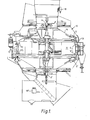
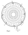
- a series of sensor assemblies S1-S8 are mounted at regular intervals around the periphery of the upper face of the stationary body 11 of a stationary matrix/rotating hood regenerative air preheater 12.
- Corresponding assemblies S'l-S'8 are similarly mounted round the lower face, but the following description will be given for only one of these series; the arrangement for the other is identical, mutatis mutandis.
- the sensor assemblies S1-S8 may be located at a said radial position or near the hub of the body 11. The number and position of the sensor assemblies S1-S8 is dependent on the size of the air preheater and the speed of rotation.
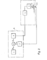
- the signal Xi derived from the comparison in the comparator is fed to the power circuitry 3 and thence through conventional power slip rings 4 to magnetic drive devices 5 mounted on the rotating hoods, to lift the sealing frames or allow them to lower.
- magnetic drive devices are disclosed in our UK patent 1559679 as well as in the said application 2091003.
- the signal Xi to the magnetic drive device 5 causes it to move in an appropriate direction to adjust the gap between the seal frame 3 and the sensor assemblies S1-S8. This signal is maintained until a signal from a succeeding sensor out of the sensor assemblies S1-S8 indicates, as the hood passes it, that the gap is now wrongly set when that signal will alter the.signal Xi and cause an adjustment in the positioning of the ,sealing frame.
- control box may be and preferably is quite remote from the regenerator so that its electronic elements are not subject to the hostile environment in which the regenerator works.
- control signals passing from that box to the magnetic drive devices being of comparatively high amplitude or power can.readily pass through conventional slip ring constructions to the drive devices borne on the rotating part.
- the sensor assemblies S1-S8 are arranged in a bridge circuit so that they are unaffected by temperature variations.
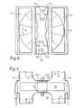
- Figures 4 and 5 show a rotating matrix machine with stationary ducts and sector plates.
- the rotating matrix 20 extends into ducts 21,22 for air and gas respectively.
- Sector plates 23,24 are located between the ducts 21,22, one on each side of the matrix 20, each sector plate 21,22 having two wings carrying sensors Sll to S14 and magnetic drive devices Dll to D14.
- the sensors used are preferably those disclosed in our UK Patent Application No. 83.20962.
- the sensor and drive arrangement on the sector plate 23 above the matrix 20 is the same as that on the sector plate 24 below the matrix 20.
- the drive devices Dll to D14 are arranged on a diagonal line.
- the number of drive devices is dependent on the size of the air preheater.
- Each drive device Dll-D14 has a corresponding sensor Sll-S14 which controls its operation, the sensor being placed in a position in advance of the corresponding drive device.
- Sll-S14 which controls its operation, the sensor being placed in a position in advance of the corresponding drive device.
- each wing of the sector plates 23 and 24 have a corresponding arrangement of sensors and drive devices.
Landscapes
- Engineering & Computer Science (AREA)
- General Engineering & Computer Science (AREA)
- Mechanical Engineering (AREA)
- Physics & Mathematics (AREA)
- Thermal Sciences (AREA)
- General Physics & Mathematics (AREA)
- Chemical & Material Sciences (AREA)
- Dispersion Chemistry (AREA)
- Air Supply (AREA)
- Manufacture Of Motors, Generators (AREA)
- General Induction Heating (AREA)
Priority Applications (1)
| Application Number | Priority Date | Filing Date | Title |
|---|---|---|---|
| DE8686202034T DE3476448D1 (en) | 1983-09-23 | 1984-08-21 | Controlling seal systems in rotary regenerative air preheaters |
Applications Claiming Priority (2)
| Application Number | Priority Date | Filing Date | Title |
|---|---|---|---|
| GB8325512 | 1983-09-23 | ||
| GB838325512A GB8325512D0 (en) | 1983-09-23 | 1983-09-23 | Controlling seal systems |
Related Child Applications (1)
| Application Number | Title | Priority Date | Filing Date |
|---|---|---|---|
| EP86202034.4 Division-Into | 1984-08-21 |
Publications (3)
| Publication Number | Publication Date |
|---|---|
| EP0137670A2 true EP0137670A2 (de) | 1985-04-17 |
| EP0137670A3 EP0137670A3 (en) | 1985-08-21 |
| EP0137670B1 EP0137670B1 (de) | 1988-05-04 |
Family
ID=10549207
Family Applications (2)
| Application Number | Title | Priority Date | Filing Date |
|---|---|---|---|
| EP86202034A Expired EP0222463B1 (de) | 1983-09-23 | 1984-08-21 | Abdichtungskontrollsystem für umlaufende Regenerativluftvorwärmer |
| EP84305686A Expired EP0137670B1 (de) | 1983-09-23 | 1984-08-21 | Abdichtungskontrollsystem für umlaufende Regenerativ-Luftvorwärmer |
Family Applications Before (1)
| Application Number | Title | Priority Date | Filing Date |
|---|---|---|---|
| EP86202034A Expired EP0222463B1 (de) | 1983-09-23 | 1984-08-21 | Abdichtungskontrollsystem für umlaufende Regenerativluftvorwärmer |
Country Status (8)
| Country | Link |
|---|---|
| US (2) | US4610297A (de) |
| EP (2) | EP0222463B1 (de) |
| JP (1) | JPS6093293A (de) |
| AU (1) | AU566293B2 (de) |
| DE (1) | DE3470947D1 (de) |
| GB (1) | GB8325512D0 (de) |
| IN (1) | IN162727B (de) |
| ZA (1) | ZA846782B (de) |
Cited By (5)
| Publication number | Priority date | Publication date | Assignee | Title |
|---|---|---|---|---|
| FR2774464A1 (fr) * | 1998-02-02 | 1999-08-06 | Gec Alsthom Stein Ind | Systeme de reduction des fuites radiales dans un rechauffeur d'air regeneratif pour equipement thermique |
| US6261092B1 (en) | 2000-05-17 | 2001-07-17 | Megtec Systems, Inc. | Switching valve |
| US6669472B1 (en) | 2002-08-28 | 2003-12-30 | Megtec Systems, Inc. | Dual lift system |
| US7150446B1 (en) | 2002-08-28 | 2006-12-19 | Megtec Systems, Inc. | Dual lift system |
| US7325562B2 (en) | 2002-05-07 | 2008-02-05 | Meggec Systems, Inc. | Heated seal air for valve and regenerative thermal oxidizer containing same |
Families Citing this family (13)
| Publication number | Priority date | Publication date | Assignee | Title |
|---|---|---|---|---|
| JPH07101134B2 (ja) * | 1988-02-02 | 1995-11-01 | 株式会社東芝 | 蓄熱材料および低温蓄熱器 |
| US5038849A (en) * | 1989-10-24 | 1991-08-13 | Damper Design, Inc. | Sealing of air heaters by deforming sector plates |
| US5063993A (en) * | 1990-10-22 | 1991-11-12 | The Babcock & Wilcox Company | Air heater with automatic sealing |
| US5029632A (en) * | 1990-10-22 | 1991-07-09 | The Babcock & Wilcox Company | Air heater with automatic sealing |
| SE517213C2 (sv) * | 1996-08-15 | 2002-05-07 | Air Preheater Abb | Anordning vid en regenerativ, roterande värmväxlare |
| US5845700A (en) * | 1996-10-31 | 1998-12-08 | Ljungstrom Technology Ab | Rotary regenerative heat exchanger |
| FI110817B (fi) * | 2000-02-01 | 2003-03-31 | Waertsilae Tech Oy Ab | Lämmöntalteenottolaitteisto ja menetelmä likaantumisen minimoimiseksi lämmöntalteenottolaitteistossa |
| US6227150B1 (en) * | 2000-04-03 | 2001-05-08 | Abb Air Preheater, Inc. | Load based control system for active leakage control in air preheater |
| US6749815B2 (en) | 2001-05-04 | 2004-06-15 | Megtec Systems, Inc. | Switching valve seal |
| GB2400646B (en) * | 2003-04-15 | 2005-05-25 | Howden Power Ltd | Ljungstrom heat exchanger and method of controlling the gap between the rotor and the hot end sector plate |
| CN101957166B (zh) * | 2010-08-27 | 2012-07-04 | 徐州燃控科技股份有限公司 | 长距离高温间隙测量探头 |
| CN113883949B (zh) * | 2021-10-25 | 2023-06-06 | 河北西柏坡第二发电有限责任公司 | 一种回转式空预器自调密封装置 |
| CN120720973B (zh) * | 2025-08-29 | 2025-10-31 | 江苏威宝仕智能科技有限公司 | 一种间隙检测装置 |
Family Cites Families (7)
| Publication number | Priority date | Publication date | Assignee | Title |
|---|---|---|---|---|
| US3232335A (en) * | 1962-03-21 | 1966-02-01 | Svenska Rotor Maskiner Ab | Rotary regenerative preheater |
| GB1391261A (en) * | 1971-06-11 | 1975-04-16 | Rolls Royce | Apparatus for measuring the clearance between a rotor and a surrounding stator of a rotary machine |
| JPS5437710B2 (de) * | 1974-09-30 | 1979-11-16 | ||
| GB1559679A (en) * | 1975-11-04 | 1980-01-23 | Davidson & Co Ltd | Regenerative air preheaters and seal frame suspension control system therefor |
| US4301858A (en) * | 1979-08-29 | 1981-11-24 | Svenska Rotor Maskiner Ab | Adjusting means of rotary regenerative sector plate heat exchangers |
| US4306612A (en) * | 1979-11-09 | 1981-12-22 | The Air Preheater Company, Inc. | Fiber optic sensing device |
| GB2091003B (en) * | 1980-11-24 | 1984-11-21 | Davidson & Co Ltd | Magnetic seal system |
-
1983
- 1983-09-23 GB GB838325512A patent/GB8325512D0/en active Pending
-
1984
- 1984-08-21 DE DE8484305686T patent/DE3470947D1/de not_active Expired
- 1984-08-21 EP EP86202034A patent/EP0222463B1/de not_active Expired
- 1984-08-21 EP EP84305686A patent/EP0137670B1/de not_active Expired
- 1984-08-30 ZA ZA846782A patent/ZA846782B/xx unknown
- 1984-08-30 US US06/646,703 patent/US4610297A/en not_active Expired - Fee Related
- 1984-09-04 AU AU32693/84A patent/AU566293B2/en not_active Ceased
- 1984-09-12 JP JP59191403A patent/JPS6093293A/ja active Pending
- 1984-09-21 IN IN723/MAS/84A patent/IN162727B/en unknown
-
1986
- 1986-02-19 US US06/830,764 patent/US4760875A/en not_active Expired - Fee Related
Cited By (7)
| Publication number | Priority date | Publication date | Assignee | Title |
|---|---|---|---|---|
| FR2774464A1 (fr) * | 1998-02-02 | 1999-08-06 | Gec Alsthom Stein Ind | Systeme de reduction des fuites radiales dans un rechauffeur d'air regeneratif pour equipement thermique |
| US6091061A (en) * | 1998-02-02 | 2000-07-18 | Alstom Energy Systems Sa | System for reducing radial leaks in a regenerative air heater for thermal equipment |
| US6261092B1 (en) | 2000-05-17 | 2001-07-17 | Megtec Systems, Inc. | Switching valve |
| US7325562B2 (en) | 2002-05-07 | 2008-02-05 | Meggec Systems, Inc. | Heated seal air for valve and regenerative thermal oxidizer containing same |
| US6669472B1 (en) | 2002-08-28 | 2003-12-30 | Megtec Systems, Inc. | Dual lift system |
| US6783111B2 (en) | 2002-08-28 | 2004-08-31 | Megtec Systems Inc. | Dual lift system |
| US7150446B1 (en) | 2002-08-28 | 2006-12-19 | Megtec Systems, Inc. | Dual lift system |
Also Published As
| Publication number | Publication date |
|---|---|
| JPS6093293A (ja) | 1985-05-25 |
| US4610297A (en) | 1986-09-09 |
| DE3470947D1 (en) | 1988-06-09 |
| ZA846782B (en) | 1985-04-24 |
| US4760875A (en) | 1988-08-02 |
| EP0137670A3 (en) | 1985-08-21 |
| GB8325512D0 (en) | 1983-10-26 |
| EP0222463B1 (de) | 1989-01-25 |
| AU566293B2 (en) | 1987-10-15 |
| AU3269384A (en) | 1985-03-28 |
| IN162727B (de) | 1988-07-02 |
| EP0137670B1 (de) | 1988-05-04 |
| EP0222463A1 (de) | 1987-05-20 |
Similar Documents
| Publication | Publication Date | Title |
|---|---|---|
| EP0137670A2 (de) | Abdichtungskontrollsystem für umlaufende Regenerativ-Luftvorwärmer | |
| DE3641538C2 (de) | ||
| EP0254537B1 (de) | Verfahren zum Antreiben eines bürstenlosen Gleichstrommotors und Gerät zum präzisen Steuern der Rotor-Startposition | |
| EP0149360B1 (de) | Rotationsmessaufnehmer | |
| US4843292A (en) | Direct drive motor system | |
| EP0065625A2 (de) | Kapazitiver Winkelmessgeber | |
| US2909717A (en) | Analogue to digital converter apparatus | |
| EP0032301B1 (de) | Drehbewegliche Einrichtung mit einem Steuersystem zum Anhalten einer Spindel in einer vorbestimmten Drehposition | |
| EP0082943A2 (de) | Rotationsmagnetmessaufnehmer und mit einem solchen aufgebaute Messaufnehmer-Motor-Anordnung | |
| WO1991007811A1 (en) | Position monitor for a stepper motor | |
| US3706924A (en) | Power supply for a stepping motor | |
| EP1339164B1 (de) | Verfahren und Vorrichtung zum Betrieb eines Synchronmotors | |
| EP0140697A2 (de) | Verfahren zum Einstellen des Startpunktes von bürstenlosen Gleichstrommotoren | |
| CN1184770A (zh) | 电梯舱门辅助定位系统 | |
| EP0615180B1 (de) | Elektrische Überwachungsanordnung | |
| US4733150A (en) | Device and method for compensating the gravitational effect on an element, raisable and lowerable by an electric motor, of a machine tool or of a robot | |
| GB1529688A (en) | Circuit arrangement for phase-alignment of a servo-drive for a rotary system | |
| GB2091003A (en) | Magnetic seal system | |
| KR102942150B1 (ko) | 무빙 마그넷 캐리어를 이용한 물품 이송 방법 및 이송시스템 | |
| US3114870A (en) | Backlash take-up system | |
| CN202794959U (zh) | 可检测凸轮运动和开关粘连的可调凸轮控制器 | |
| KR20240097132A (ko) | 지능형 기계 및 로봇 구동용 스마트 액추에이터 | |
| TW202614354A (zh) | 用於處理在旋轉中的產品的系統 | |
| JPH03230365A (ja) | モータインデックス信号検知装置及び検知方法 | |
| SU891338A1 (ru) | Устройство дл контрол прилегани заготовок к базовой поверхности станка |
Legal Events
| Date | Code | Title | Description |
|---|---|---|---|
| PUAI | Public reference made under article 153(3) epc to a published international application that has entered the european phase |
Free format text: ORIGINAL CODE: 0009012 |
|
| AK | Designated contracting states |
Designated state(s): DE FR GB |
|
| PUAL | Search report despatched |
Free format text: ORIGINAL CODE: 0009013 |
|
| AK | Designated contracting states |
Designated state(s): DE FR GB |
|
| 17P | Request for examination filed |
Effective date: 19851017 |
|
| 17Q | First examination report despatched |
Effective date: 19860423 |
|
| GRAA | (expected) grant |
Free format text: ORIGINAL CODE: 0009210 |
|
| AK | Designated contracting states |
Kind code of ref document: B1 Designated state(s): DE FR GB |
|
| REF | Corresponds to: |
Ref document number: 3470947 Country of ref document: DE Date of ref document: 19880609 |
|
| ET | Fr: translation filed | ||
| PLBE | No opposition filed within time limit |
Free format text: ORIGINAL CODE: 0009261 |
|
| STAA | Information on the status of an ep patent application or granted ep patent |
Free format text: STATUS: NO OPPOSITION FILED WITHIN TIME LIMIT |
|
| 26N | No opposition filed | ||
| PGFP | Annual fee paid to national office [announced via postgrant information from national office to epo] |
Ref country code: GB Payment date: 19900808 Year of fee payment: 7 |
|
| PGFP | Annual fee paid to national office [announced via postgrant information from national office to epo] |
Ref country code: FR Payment date: 19900817 Year of fee payment: 7 |
|
| PGFP | Annual fee paid to national office [announced via postgrant information from national office to epo] |
Ref country code: DE Payment date: 19900822 Year of fee payment: 7 |
|
| PG25 | Lapsed in a contracting state [announced via postgrant information from national office to epo] |
Ref country code: GB Effective date: 19910821 |
|
| GBPC | Gb: european patent ceased through non-payment of renewal fee | ||
| PG25 | Lapsed in a contracting state [announced via postgrant information from national office to epo] |
Ref country code: FR Effective date: 19920430 |
|
| PG25 | Lapsed in a contracting state [announced via postgrant information from national office to epo] |
Ref country code: DE Effective date: 19920501 |
|
| REG | Reference to a national code |
Ref country code: FR Ref legal event code: ST |