EP0137708B1 - Feuer- und Explosions-Detektion und -Unterdrückung - Google Patents
Feuer- und Explosions-Detektion und -Unterdrückung Download PDFInfo
- Publication number
- EP0137708B1 EP0137708B1 EP84305982A EP84305982A EP0137708B1 EP 0137708 B1 EP0137708 B1 EP 0137708B1 EP 84305982 A EP84305982 A EP 84305982A EP 84305982 A EP84305982 A EP 84305982A EP 0137708 B1 EP0137708 B1 EP 0137708B1
- Authority
- EP
- European Patent Office
- Prior art keywords
- fire
- detection
- unit
- suppression
- threshold
- Prior art date
- Legal status (The legal status is an assumption and is not a legal conclusion. Google has not performed a legal analysis and makes no representation as to the accuracy of the status listed.)
- Expired
Links
Images


Classifications
-
- G—PHYSICS
- G08—SIGNALLING
- G08B—SIGNALLING SYSTEMS, e.g. PERSONAL CALLING SYSTEMS; ORDER TELEGRAPHS; ALARM SYSTEMS
- G08B17/00—Fire alarms; Alarms responsive to explosion
-
- G—PHYSICS
- G08—SIGNALLING
- G08B—SIGNALLING SYSTEMS, e.g. PERSONAL CALLING SYSTEMS; ORDER TELEGRAPHS; ALARM SYSTEMS
- G08B25/00—Alarm systems in which the location of the alarm condition is signalled to a central station, e.g. fire or police telegraphic systems
- G08B25/01—Alarm systems in which the location of the alarm condition is signalled to a central station, e.g. fire or police telegraphic systems characterised by the transmission medium
- G08B25/014—Alarm signalling to a central station with two-way communication, e.g. with signalling back
Definitions
- the invention relates to fire and explosion detection and extinguishing or suppression and more specifically to a system for protecting a large area against fire or explosion such as a ship or part of a ship for example.
- fire includes “explosion”
- compression includes “extinguishing” and grammatical derivatives.
- US-A-4,162,485 discloses a multi-zone fire protection system in which each zone is provided with a fire detector and a fire suppressor, and a common control circuit couples each detectorsuppressor pair to a respective pull-box station located in the vicinity of the associated zone.
- a fire detection and suppression system comprising a plurality of individual fire detection-suppression units placed at different positions within an area to be protected and each capable of operating independently, in response to its detection of a fire condition exceeding a first threshold, to release a fire suppressant, and a master control unit connected to all of the fire detection-suppression units whereby to be signalled by each of them when each such unit detects a fire condition exceeding the first threshold, characterised in that each fire detection-suppression unit is also capable of detecting a fire condition not exceeding the first threshold but exceeding a second, lower, threshold, and in that the master control unit is operative in response to any of the fire detection-suppression units detecting a fire condition exceeding the first threshold to cause at least one other such unit to release fire suppressant if that other unit is detecting a fire condition exceeding the second threshold but not the first threshold, the said other unit being physically adjacent to the unit detecting a fire condition exceeding the first threshold.
- the system to be described is in this example for suppressing hydrocarbon fires in ships, though is not restricted to such an application.
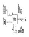
- FIG. 1 shows a block diagram of the system.
- This Figure shows eight (in this example) fire detection and suppression units, 6, 8, 10, 12, 14 16, 18 and 20.
- Each unit comprises a detector head 6A, 8A, 10A, 12A, 14A, 16A, 18A, 20A and a fire suppressor, 6B, 88, 10B, 12B, 14B, 16B, 18B, 20B and associated circuitry not shown in Figure 1.
- Each fire suppressor comprises in this example a bottle containing Halon fire suppressant which can be discharged from the bottle under pressure by an electrical signal. All eight units are electrically connected by a data bus 21 to a master station 22. The eight units are physically positioned around an area 23 to be protected. In this example, this is an area in a ship, and in such an example the master station 22 could be positioned in the ship control centre.
- Each unit, 6,8,10,12,14,16,18,20 incorporates its own electrical standby power supply.
- All the units 6 to 20 are connected to a manually operable emergency button 24 via respective lines 26.
- the master control unit 22 is connected to button 24 by a line 28.
- Figure 2 shows the unit 6 in more detail. As shown, it comprises two radiation sensors 30 and 32.
- Sensor 30 may be in the form of a thermopile and is associated with a filter 34 having a narrow radiation passband at 4:4 microns. Infra-red radiation at this frequency therefore falls on the sensor 30 which produces a corresponding electrical signal on a line 36 to one input of an AND gate 38.
- Sensor 32 may be a silicon photo-diode which is responsive to radiation in a narrow band centred at 0.9 microns and produces a corresponding electrical signal on the line 40 to the AND gate 38 in response to such radiation.
- Amplifier 42 is fed to a threshold comparator 44 which compares the amplitude of the amplifier output with two internally generated thresholds. The first of these thresholds corresponds to a large fire and the second threshold, which is lower than the first threshold, corresponds to a small fire. If the signal on line 45 from amplifier 42 exceeds the first threshold, a first or "high” control signal is produced on a line 48 (but not on line 46), but if the signal on line 45 exceeds the second threshold (but not the first threshold) a second or "low” control signal is produced on a line 46.
- the first threshold (corresponding to a "large" fire) could comprise simply a higher magnitude threshold corresponding to a fire significantly larger than the 65 millimetre panfire at 1,200 millimetres or could consist of or include a rate of rise threshold - so that the signal on line 48 would only be produced if the signal on line 45 was rising at at least a relatively high rate.
- the second threshold (corresponding to the "small" fire) may simply be a low magnitude threshold corresponding, for example, to the radiation level which would be emitted from a 65 millimetre panfire at a distance of 1,200 millimetres.
- the second threshold may be or include a rate of rise threshold. In other words, the signal would only be produced on line 46 if the signal on line 45 was rising at at least a relatively low rate.
- Line 46 is connected to an encoder unit 52 and also, via a line to one input of an AND gate 56.
- Line 48 is connected to one input of an OR gate 58 and also to an encoder 60.
- the output of the OR gate 58 is connected through an output unit 62 to the fire suppressor 6B of the unit under discussion via the line 64.
- the encoders 52 and 60 encode the signals which they respectively receive and feed corresponding data output signals to the master control unit 22 via the data bus 21.
- information is also received from the master control unit 22 via the data bus 21 and this data is decoded by a decoder 72 and output (in a manner to be explained) on the line 74 connected to the second input of the AND gate 56 and on a line 76 connected to the second input of the OR gate 58.
- the third input of the OR gate 58 is received via a line 78 from the AND gate 56.
- a pressure transducer 80 monitors the pressure of the suppressant in the suppressor 6B and produces a corresponding electrical signal on a line 82 which is encoded by the encoder 52 and fed to.the master control unit 22 via the data bus 21.
- An electrical power supply for the unit 6 is received via power supply lines 84 (connected in parallel to all the units).
- Lines 84 feed a battery charger and regulator unit 86 which produces a stable output supply at the required relatively low voltage on lines 88 and also maintains a nickel-cadmium battery 90 charged.
- Lines 88 are connected to provide a power supply to all the necessary components of the unit 6 via connections not shown.
- a line 92 monitors the voltage of the nickel-cadmium battery 90 and encoder 52 feeds corresponding data to the master control unit 22 via the data bus 21.
- Line 26 from the emergency button 24 (see Figure 1) is connected to the fourth input of the OR gate 58.
- the encoders 52 and 60 encode the data which they transmit onto the data bus in combination with suitable address signals indicating the identity of the unit (unit 6 in this example) from which the data originates.
- the decoder 72 is operative to decode data on the data bus which is addressed to the particular unit.
- Any other unit which detects the same fire and which receives such radiation that its threshold comparator produces a "high" signal on its line 48 will operate in identical manner and will cause its fire suppressor to release suppressant.
- the master control unit 22 continually monitors the status of all the fire detection-suppression units 6 to 20. When it detects that any one of them is producing a "high" control (on its line 48), the master control unit 22 addresses a "status 1" signal to those fire detection-suppression units which are immediately physically adjacent to the unit producing the high control signal. The "status 1" signal is detected by decoder 72 and produces a signal on line 74. If the unit is producing a low control signal on line 46, AND gate 56 will have been enabled via line 54 and thus line 78 will be energised and will cause the suppressor to release suppressant, this fact being signalled back to the master control unit and via line 82 of that unit. If the immediately adjacent units are not producing low control signals, then of course the signal on line 74 will not cause release of suppressant by them.
- Mass release of suppressant may also be carried out, completely independently of the master control unit 22, by means of the emergency button 24 (Fig. 1). This energises all the lines 26. As shown in Figure 2, line 26 operates the suppressor via the OR gate 58.
- line 28 (Fig. 1) is to provide an additional or back-up path by means of which the master control unit 22 may cause mass release of suppressant.
- corresponding signals are not only fed to all of the individual units via the data bus 21 but such a signal is also fed to the emergency button 24 via line 28 and causes the emergency button to energise all the lines 26.
- the master control station 22 carries out a number of other functions. For example it may be programmed to monitor the statuses of all the individual units so as to sense when at least a predetermined number of them either have released their suppressant or their suppressors are non-functional for some other reason (as sensed by the pressure transducer 80). When this predetermined number is exceeded, the master control station will no longer react to receipt of a high control signal (on line 48) from any of the units by sending a "status 1" signal to the immediately adjacent units. In other words, those immediately adjacent units will not release their suppressant even if they do produce a low control signal on their lines 46. This preserves at least some of the units ready for manual operation in the event of an emergency. Of course, each of the units can still operate to release suppressant in the event of its producing a high control signal; the master control station cannot prevent this.
- the master control station also monitors the control signals produced by all the individual units 6 to 20 and displays and/or records the signals being produced, along with the pressure within each transducer and the state of its power supply.
- it carries out this process by progressing through a sequence of operations in which it addresses "status demand" signals to each of the units 6 to 20 in turn, in response to which they output the required data on to data bus 21.
- the purpose of the encoder 60 is to transmit a "interrupt" signal to the master control station to interrupt its sequence of operations in the event of a high control signal being produced by any one unit. This may be necessary or advantageous when there are a relatively large number of units since the sequence of operations of the master control station will in such circumstances take a relatively long time and it is desirable that it be interrupted when a high control signal is produced by any unit so as to be able to react immediately to that signal. When there are only a small number of individual units in the system, the provision of this "interrupt" facility may not be necessary.
- the purpose of the sensor 32 in each unit 6 to 20 is to enable the system to discriminate against spurious (that is, non-fire) sources of radiation which may be present in the area 23. For example, if there are hot surfaces (of machinery and the like) in the area, these may emit sufficient radiation at 4.4 microns to produce a significant signal on line 36. However, such sources will emit insufficient radiation at 0.9. microns to enable gate 38. Such spurious radiation sources will therefore not cause production of a high or low control signal.
- spurious sources of radiation which may be present in the area 23. For example, if there are hot surfaces (of machinery and the like) in the area, these may emit sufficient radiation at 4.4 microns to produce a significant signal on line 36. However, such sources will emit insufficient radiation at 0.9. microns to enable gate 38. Such spurious radiation sources will therefore not cause production of a high or low control signal.
- the master control station 22 is connected via the data bus 21 to produce the listed output signals; that is, the "status 1" signal, the "status 2" signal and the "status demand” signal.
- the station 22 receives the listed input signals from each unit 6 to 20; that is, whether it is producing a low or high control signal (on lines 46 and 48), the pressure in its suppressor, the state of its electrical power supply (and any other parameters monitored).
- a manual control 98 is connected to the master station 22 to cause it to produce mass release of suppressant or flooding of the area in the manner explained.
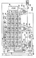
- FIG. 4 illustrates in more detail one form which the master station 22 may have.
- the master station 22 incorporates storage units 100, 102, 104, 106, 108, 110, 112 and 114 of any suitable form, each of which has four storage sections, labelled A, B, C and D. There is a respective storage unit provided for each of the eight fire detection-suppression units 6 to 20, shown in this example.
- Storage unit 100 corresponds to detection-suppression unit 6 and similarly for the remainder in numerical order.
- the storage sections A are for storing "low" control signals (from the respective detection-suppression units), the storage sections B are for storing "high” control signals, the storage sections C are for storing the status of the suppressors (e.g. 6B) in the detection-suppression units, that is, for storing whether, for example, each such suppressor has or has not discharged its suppressant, and the storage sections D are for storing the status of the standby power unit 90 in each detection-suppression unit.
- the suppressors e.g. 6B
- the decoder 116 will ensure that this information is stored in the appropriate storage section B; and so on for information relating to the operational status of the detection-suppression units and for the status of their standby power unit 90.
- the decoder 116 may decode the data on the data bus 21 serially, that is, it may decode the data arriving in respect of each of the detection-suppression units in turn for example. Such serial operation may be controlled by means of a line 134 from a timing unit 136. In certain configurations additional storage units (not shown in Figure 4) will be allocated to store diagnostic operational status of detection-suppression units - thus providing fault identification.
- All the storage sections A are connected to a data output channel 140 which in turn is connected to a display unit 138 by means of a channel 140.
- all the storage units B are connected to a data output channel 142 and thence to the display unit 138;
- all the storage sections C are connected to a data output channel 146 and thence to the display unit 138, and all the storage sections D are connected to a data output channel 150 and thence to the display unit 138.
- the display unit 138 continually displays the status of all the detection-suppression units, displaying which of them is producing a "low” signal, and which of them is producing a "high” control signal.
- display unit 138 displays the status of the suppressor in each detection-suppression unit, that is, whether it is available or not for discharge of suppressant, and the status of the battery 90 in each of the detection-suppression units.
- display unit 138 will indicate a "fault" condition of detection-suppression units.
- the master control station 22 also incorporates three control units 160, 162 and 164.
- the control unit 160 has an output address channel 166 which is connected to each of the storage sections B and by means of which it can address each of them in turn and cause it to feed back to the unit 160, on a data channel 168, data indicating whether or not that particular storage section B is storing a "high" control signal from the corresponding detection-suppression unit.
- the unit 160 is controlled to monitor the storage sections B sequentially by signals from the timing unit 136 on a line 170.
- the control unit 162 is connected by means of an output address channel 171 to monitor the states of the storage sections A and operates in synchronism with the control unit 160.
- the control unit 162 is programmed so that it does not monitor the storage section A of the same storage unit 100 to 114 as the control unit 160 is monitoring at that time.
- the control unit 162 is arranged so that, when the control unit 160 is monitoring the storage section B of a particular storage unit, the control unit 162 is monitoring the storage sections A of the storage units corresponding to the immediately adjacent detection-suppression units. For example, it could be monitoring those detection-suppression units which are immediately on opposite sides of a particular detection-suppression unit. However, other arrangements are possible.
- the control unit 162 is connected to be controlled by the timing signals on line 170. Data indicating whether the particular storage sections A are storing "low” control signals or not is fed back to the control unit 162 on a channel 172. In certain configurations diagnostic "fault" information will also be monitored e.g. from the additional storage units by control units 160 and 162. If a fault is indicated in operation any enable signal will be suppressed.
- the timing signals on line 170 cause the control unit 160 to monitor the storage sections B in turn. If any of them is storing data representing a "high" control signal, an enable signal is fed out on a line 174 to AND gates 174 and 175.
- the control unit 162 monitors the storage sections A corresponding to the physically adjacent detection-suppression units. If they, or either of them, contains data representing a "low" control signal, corresponding signals are output by the control unit 162 on lines 176 and 178 connected to the gates 174 and 175, As these gates are enabled, the signals on lines 176 and 178 pass through to an encoder 180 which transmits signals to the corresponding detection-suppression units for setting off their suppressors.
- the control unit 160 monitors the storage sections B in sequence (with the control unit 162 operating in synchronism in the manner described).
- the master control station may have the "interrupt” facility described above in which an "interrupt” signal can be generated by the encoder 60 ( Figure 2) in a detection-suppression unit producing a "high” control signal.
- Such an "interrupt” signal may be decoded by the decoder 116 in the master station 22 (Fig. 4) and fed to the control units 160 and 162 by means of a channel 182.
- Any such "interrupt" signal will be associated with data identifying the detection-suppression unit from which the signal originates and this data will cause the control unit 160 to inspect the section B of the adjacent storage unit and will also cause the control unit 162 to inspect the storage sections A of the physically adjacent detection-suppression units in the manner defined.
- the control unit 164 is controlled by the timing signals on the line 170 and has an output address channel 190 by means of which it monitors the storage sections C of all the storage units 100 to 114 in sequence. As it monitors each storage section C in this way, the data in that storage section, relating to the status of the suppressor in the corresponding detection-suppression unit, is fed back to the control unit 164 on a data channel 192. In this way, the control unit 164 monitors the number of detection-suppression units whose suppressors have discharged.
- control unit 160 When this number exceeds a predetermined threshold, the control unit 160 operates an inhibit gate 194 to prevent the control unit 162 from causing discharge of suppressant by any of the detection-suppression units 6 to 20.
- a manual over-ride signal may be generated on a line 196 and fed via the encoder 180 to cause discharge of suppressant by the suppressors of all the detection-suppression units irrespective of the number of detection-suppression units already operated.
- Energisation of line 196 also provides a back-up path for the same purpose via the emergency button 24 in the manner explained.
- each of the fire detection-suppression units 6 to 20 is capable of operating completely independently of each other and independently of the master station 22 to release fire suppressant in the event of its detection of a "large" fire.
- the master control station can allow each of the units immediately adjacent to a unit which has detected a large fire to release the suppressant provided low threshold detection of flame is satisfied.
- the system may be configured to activate suppressors adjacent to such a fire detection-suppression unit although the detectors associated with these detection-suppression units have not met the threshold defined by "small” fires.
- the units can all be caused to release fire suppressant either by means of the master control station 22 or by means of the emergency button 24.
- each of the individual units is still capable of operating to release fire suppressant in the event of detection of a large fire.
- control station 22 may be backed up by a further control station either on data bus 21 or a second parallel data bus.
Landscapes
- Business, Economics & Management (AREA)
- Emergency Management (AREA)
- Physics & Mathematics (AREA)
- General Physics & Mathematics (AREA)
- Alarm Systems (AREA)
- Fire Alarms (AREA)
- Fire-Extinguishing By Fire Departments, And Fire-Extinguishing Equipment And Control Thereof (AREA)
Claims (10)
Applications Claiming Priority (2)
| Application Number | Priority Date | Filing Date | Title |
|---|---|---|---|
| GB8324136 | 1983-09-09 | ||
| GB838324136A GB8324136D0 (en) | 1983-09-09 | 1983-09-09 | Fire and explosion detection and suppression |
Publications (3)
| Publication Number | Publication Date |
|---|---|
| EP0137708A2 EP0137708A2 (de) | 1985-04-17 |
| EP0137708A3 EP0137708A3 (en) | 1986-11-20 |
| EP0137708B1 true EP0137708B1 (de) | 1989-10-18 |
Family
ID=10548516
Family Applications (1)
| Application Number | Title | Priority Date | Filing Date |
|---|---|---|---|
| EP84305982A Expired EP0137708B1 (de) | 1983-09-09 | 1984-08-31 | Feuer- und Explosions-Detektion und -Unterdrückung |
Country Status (8)
| Country | Link |
|---|---|
| US (1) | US4597451A (de) |
| EP (1) | EP0137708B1 (de) |
| JP (1) | JPS6072569A (de) |
| CA (1) | CA1227554A (de) |
| DE (1) | DE3480236D1 (de) |
| DK (1) | DK163845C (de) |
| ES (1) | ES8600950A1 (de) |
| GB (2) | GB8324136D0 (de) |
Families Citing this family (30)
| Publication number | Priority date | Publication date | Assignee | Title |
|---|---|---|---|---|
| JPS61150096A (ja) * | 1984-12-25 | 1986-07-08 | ニツタン株式会社 | 火災警報装置 |
| JPS6357066A (ja) * | 1986-08-27 | 1988-03-11 | 株式会社竹中工務店 | 放水ノズルのターゲット識別装置 |
| US5350019A (en) * | 1986-09-05 | 1994-09-27 | Nohmi Bosai Kogyo Kabushiki Kaisha | Fire protection system |
| JP2794697B2 (ja) * | 1987-10-05 | 1998-09-10 | 石川島播磨重工業株式会社 | 船舶用制御装置 |
| US4988884A (en) * | 1988-11-22 | 1991-01-29 | Walter Kidde Aerospace, Inc. | High temperature resistant flame detector |
| GB8912273D0 (en) * | 1989-05-27 | 1989-07-12 | British Aerospace | Fire suppression systems for vehicles |
| US5153722A (en) * | 1991-01-14 | 1992-10-06 | Donmar Ltd. | Fire detection system |
| CA2036881C (en) * | 1991-02-22 | 1994-06-28 | Jean-Pierre Asselin | Fire emergency, sprinkling control system and method thereof |
| FI96483C (sv) * | 1994-05-17 | 1996-07-10 | Goeran Sundholm | Installation för brandbekämpning samt sprinkler |
| DK0797465T3 (da) * | 1994-05-17 | 2000-04-25 | Goeran Sundholm | Sprinklerhoved |
| US5574434A (en) * | 1995-08-11 | 1996-11-12 | Liu; Hung-Chang | Alarm for heat multistaged detecting |
| EP0762358B1 (de) * | 1995-08-18 | 2001-10-31 | Gsbs Development Corporation | Feueralarmsystem |
| US5937077A (en) * | 1996-04-25 | 1999-08-10 | General Monitors, Incorporated | Imaging flame detection system |
| DE19638626C2 (de) * | 1996-09-20 | 1998-12-24 | Amtech R Int Inc | Feuerlöschanlage |
| US6119574A (en) * | 1998-07-02 | 2000-09-19 | Battelle Memorial Institute | Blast effects suppression system |
| US7456750B2 (en) | 2000-04-19 | 2008-11-25 | Federal Express Corporation | Fire suppression and indicator system and fire detection device |
| US7333129B2 (en) * | 2001-09-21 | 2008-02-19 | Rosemount Aerospace Inc. | Fire detection system |
| US7623028B2 (en) * | 2004-05-27 | 2009-11-24 | Lawrence Kates | System and method for high-sensitivity sensor |
| US7810577B2 (en) * | 2005-08-30 | 2010-10-12 | Federal Express Corporation | Fire sensor, fire detection system, fire suppression system, and combinations thereof |
| JP4927935B2 (ja) | 2006-03-22 | 2012-05-09 | フェデラル エクスプレス コーポレイション | 膨張剤を含む、火災抑制装置および方法 |
| EP2054126B1 (de) * | 2006-08-24 | 2013-09-25 | Roger Rüden | Vorrichtung zur verhinderung einer explosion |
| GB2458281B (en) * | 2008-03-11 | 2012-10-31 | Selectamark Security Systems Plc | A security system |
| US8646540B2 (en) * | 2010-07-20 | 2014-02-11 | Firetrace Usa, Llc | Methods and apparatus for passive non-electrical dual stage fire suppression |
| JP5640950B2 (ja) * | 2011-10-31 | 2014-12-17 | 株式会社デンソー | 車両用制御装置 |
| CN102708645B (zh) * | 2012-05-18 | 2013-10-30 | 哈尔滨工程大学 | 一种船舶舱室火灾连锁报警优先级评估方法 |
| CN102682560B (zh) * | 2012-05-22 | 2013-10-30 | 哈尔滨工程大学 | 一种船舶舱室火灾连锁报警等级评估装置 |
| CN103440728A (zh) * | 2013-09-03 | 2013-12-11 | 哈尔滨工程大学 | 分布智能控制船舶消防系统连锁性失效测评方法 |
| EP3086864B1 (de) | 2013-12-23 | 2023-10-04 | Tyco Fire Products LP | Gesteuertes system und verfahren zur brandschutz eines speichers |
| EP3763420B1 (de) * | 2014-06-09 | 2025-09-03 | Tyco Fire Products LP | Gesteuertes system und verfahren zum brandschutz eines speichers |
| EP4087664A4 (de) * | 2020-01-06 | 2024-01-17 | Tyco Fire Products LP | Elektronisches feuerdetektionssystem zur verwendung in restaurants |
Family Cites Families (15)
| Publication number | Priority date | Publication date | Assignee | Title |
|---|---|---|---|---|
| GB1270388A (en) * | 1968-06-28 | 1972-04-12 | Graviner Colnbrook Ltd | Improvements in or relating to detectors of smoke and the like |
| CH556670A (fr) * | 1969-10-08 | 1974-12-13 | Factory Mutual Res Corp | Installation fixe d'extinction automatique de feu. |
| US3884304A (en) * | 1972-07-24 | 1975-05-20 | Robert P Messerschmidt | Fire safety systems |
| JPS5120495A (ja) * | 1974-08-13 | 1976-02-18 | Nippon Keibi Hosho Kk | Jidoshokasochi |
| US3993138A (en) * | 1975-04-24 | 1976-11-23 | The United States Of America As Represented By The Secretary Of The Interior | Fire prevention system |
| US4162485A (en) * | 1975-07-14 | 1979-07-24 | Walter Kidde And Company, Inc. | Fire protection apparatus |
| US4227577A (en) * | 1976-07-26 | 1980-10-14 | Security Patrols Co., Ltd. | Fire-extinguishing system |
| US4082148A (en) * | 1976-07-26 | 1978-04-04 | A-T-O Inc. | Fire protection system |
| GB1598475A (en) * | 1978-05-24 | 1981-09-23 | Security Patrols Co | Automatic fire-extinguishing system |
| IL54138A (en) * | 1978-02-27 | 1983-10-31 | Spectronix Ltd | Fire and explosion detection and suppression system |
| IL69489A (en) * | 1978-02-27 | 1991-06-10 | Spectronix Ltd | Fire and explosion suppression apparatus |
| JPS56132690A (en) * | 1980-03-19 | 1981-10-17 | Hochiki Co | Fire detector |
| GB2076148B (en) * | 1980-05-17 | 1984-08-30 | Graviner Ltd | Improvements in and relating to fire or explosion detection |
| FR2485773A1 (fr) * | 1980-06-24 | 1981-12-31 | Promocab | Systeme de protection d'une zone contre l'agression humaine |
| JPS595740Y2 (ja) * | 1981-06-19 | 1984-02-21 | 宏之 金井 | 金属針布 |
-
1983
- 1983-09-09 GB GB838324136A patent/GB8324136D0/en active Pending
-
1984
- 1984-08-31 EP EP84305982A patent/EP0137708B1/de not_active Expired
- 1984-08-31 GB GB08421997A patent/GB2146243B/en not_active Expired
- 1984-08-31 DE DE8484305982T patent/DE3480236D1/de not_active Expired
- 1984-09-05 US US06/647,566 patent/US4597451A/en not_active Expired - Fee Related
- 1984-09-07 JP JP59186656A patent/JPS6072569A/ja active Granted
- 1984-09-07 DK DK430184A patent/DK163845C/da not_active IP Right Cessation
- 1984-09-07 CA CA000462700A patent/CA1227554A/en not_active Expired
- 1984-09-07 ES ES535747A patent/ES8600950A1/es not_active Expired
Also Published As
| Publication number | Publication date |
|---|---|
| JPH0451187B2 (de) | 1992-08-18 |
| DK430184A (da) | 1985-03-10 |
| GB2146243A (en) | 1985-04-17 |
| JPS6072569A (ja) | 1985-04-24 |
| CA1227554A (en) | 1987-09-29 |
| DK163845B (da) | 1992-04-06 |
| DK163845C (da) | 1992-08-24 |
| DK430184D0 (da) | 1984-09-07 |
| US4597451A (en) | 1986-07-01 |
| GB2146243B (en) | 1986-11-05 |
| GB8421997D0 (en) | 1984-10-24 |
| DE3480236D1 (en) | 1989-11-23 |
| EP0137708A2 (de) | 1985-04-17 |
| GB8324136D0 (en) | 1983-10-12 |
| ES535747A0 (es) | 1985-10-16 |
| ES8600950A1 (es) | 1985-10-16 |
| EP0137708A3 (en) | 1986-11-20 |
Similar Documents
| Publication | Publication Date | Title |
|---|---|---|
| EP0137708B1 (de) | Feuer- und Explosions-Detektion und -Unterdrückung | |
| US4101887A (en) | Monitored fire protection system | |
| US4195286A (en) | Alarm system having improved false alarm rate and detection reliability | |
| US5894415A (en) | Fault tolerant power supply including a switching mechanism for controlling the operation of plural voltage converters in response to changing input voltage levels | |
| US4149159A (en) | Fire detection system | |
| US5151683A (en) | Power supply control device in fire alarm system | |
| GB2129179A (en) | Atmospheric abnormality detection alarm systems | |
| US4719973A (en) | Fire and explosion detection and suppression | |
| JP3054974B2 (ja) | トンネル用防災設備 | |
| US4356476A (en) | Multiple alarm detector monitoring and command system | |
| US4740787A (en) | Centralized monitoring method for security system | |
| US4013128A (en) | Modular fire protection system | |
| RU26430U1 (ru) | Система контроля пожарной безопасности | |
| US6100807A (en) | Rack protection monitor | |
| EP0269747B1 (de) | Übertragungsschaltung bei einrichtungen zur verhinderung von katastrophen | |
| KR101744641B1 (ko) | 선박 화재 감지 장치 | |
| EP1478440A1 (de) | Verbesserung an oder in verbindung mit feuerunterdrückungssystem | |
| JPS5769345A (en) | Protection system of computer | |
| KR200372357Y1 (ko) | 선형 화재감지튜브 및 무전원 자동 소화시스템 | |
| JP2552272B2 (ja) | 自動火災報知装置 | |
| JPS6315967A (ja) | 監視システム | |
| TWM627195U (zh) | 複合受信迴路之消防中繼器 | |
| FI933470A7 (fi) | Paloturvallisuusjärjestelmä | |
| JP2878319B2 (ja) | 火災報知設備 | |
| JPH01119896A (ja) | 遠隔監視装置 |
Legal Events
| Date | Code | Title | Description |
|---|---|---|---|
| PUAI | Public reference made under article 153(3) epc to a published international application that has entered the european phase |
Free format text: ORIGINAL CODE: 0009012 |
|
| AK | Designated contracting states |
Designated state(s): DE FR NL |
|
| PUAL | Search report despatched |
Free format text: ORIGINAL CODE: 0009013 |
|
| AK | Designated contracting states |
Kind code of ref document: A3 Designated state(s): DE FR NL |
|
| 17P | Request for examination filed |
Effective date: 19861208 |
|
| 17Q | First examination report despatched |
Effective date: 19880701 |
|
| RAP3 | Party data changed (applicant data changed or rights of an application transferred) |
Owner name: GRAVINER LIMITED |
|
| GRAA | (expected) grant |
Free format text: ORIGINAL CODE: 0009210 |
|
| RAP3 | Party data changed (applicant data changed or rights of an application transferred) |
Owner name: KIDDE-GRAVINER LIMITED |
|
| AK | Designated contracting states |
Kind code of ref document: B1 Designated state(s): DE FR NL |
|
| REF | Corresponds to: |
Ref document number: 3480236 Country of ref document: DE Date of ref document: 19891123 |
|
| ET | Fr: translation filed | ||
| PLBE | No opposition filed within time limit |
Free format text: ORIGINAL CODE: 0009261 |
|
| STAA | Information on the status of an ep patent application or granted ep patent |
Free format text: STATUS: NO OPPOSITION FILED WITHIN TIME LIMIT |
|
| 26N | No opposition filed | ||
| PGFP | Annual fee paid to national office [announced via postgrant information from national office to epo] |
Ref country code: FR Payment date: 19910808 Year of fee payment: 8 |
|
| PGFP | Annual fee paid to national office [announced via postgrant information from national office to epo] |
Ref country code: DE Payment date: 19910930 Year of fee payment: 8 |
|
| PGFP | Annual fee paid to national office [announced via postgrant information from national office to epo] |
Ref country code: NL Payment date: 19920831 Year of fee payment: 9 |
|
| PG25 | Lapsed in a contracting state [announced via postgrant information from national office to epo] |
Ref country code: FR Effective date: 19930430 |
|
| PG25 | Lapsed in a contracting state [announced via postgrant information from national office to epo] |
Ref country code: DE Effective date: 19930501 |
|
| REG | Reference to a national code |
Ref country code: FR Ref legal event code: ST |
|
| PG25 | Lapsed in a contracting state [announced via postgrant information from national office to epo] |
Ref country code: NL Effective date: 19940301 |
|
| NLV4 | Nl: lapsed or anulled due to non-payment of the annual fee |