EP0137745A2 - Direction finding systems - Google Patents
Direction finding systems Download PDFInfo
- Publication number
- EP0137745A2 EP0137745A2 EP84306249A EP84306249A EP0137745A2 EP 0137745 A2 EP0137745 A2 EP 0137745A2 EP 84306249 A EP84306249 A EP 84306249A EP 84306249 A EP84306249 A EP 84306249A EP 0137745 A2 EP0137745 A2 EP 0137745A2
- Authority
- EP
- European Patent Office
- Prior art keywords
- deriving
- antennas
- antenna
- bearing
- received
- Prior art date
- Legal status (The legal status is an assumption and is not a legal conclusion. Google has not performed a legal analysis and makes no representation as to the accuracy of the status listed.)
- Granted
Links
Images

Classifications
-
- G—PHYSICS
- G01—MEASURING; TESTING
- G01S—RADIO DIRECTION-FINDING; RADIO NAVIGATION; DETERMINING DISTANCE OR VELOCITY BY USE OF RADIO WAVES; LOCATING OR PRESENCE-DETECTING BY USE OF THE REFLECTION OR RERADIATION OF RADIO WAVES; ANALOGOUS ARRANGEMENTS USING OTHER WAVES
- G01S3/00—Direction-finders for determining the direction from which infrasonic, sonic, ultrasonic or electromagnetic waves, or particle emission, not having a directional significance, are being received
- G01S3/02—Direction-finders for determining the direction from which infrasonic, sonic, ultrasonic or electromagnetic waves, or particle emission, not having a directional significance, are being received using radio waves
- G01S3/14—Systems for determining direction or deviation from predetermined direction
- G01S3/46—Systems for determining direction or deviation from predetermined direction using antennas spaced apart and measuring phase or time difference between signals therefrom, i.e. path-difference systems
- G01S3/48—Systems for determining direction or deviation from predetermined direction using antennas spaced apart and measuring phase or time difference between signals therefrom, i.e. path-difference systems the waves arriving at the antennas being continuous or intermittent and the phase difference of signals derived therefrom being measured
Definitions
- the present invention relates to direction finding (DF) systems and more specifically, to DF systems using circular antenna arrays.
- the DF system In most typical electromagnetic environments in which DF systems are currently used, there are many signals being received by the antennas . Unless the receivers used are to be tuned to a particular frequency , it is essential that the DF system should be capable of accurately indicating the presence of and discriminating between the bearing directions of a large number of signals of different frequencies covering the whole of a received wide bandwidth.
- U.K. Patent Application No. 2076152A shows a direction finding system using a 4 antenna Adcock array which is adapted to be frequency selective.
- the signals received by each antenna are fed to a Fast Fourier Transform (FFT) processing block which outputs a spectrum of the received signal.
- FFT Fast Fourier Transform
- Cross spectra of the signals received from opposite antennas are produced and, from these, a bearing calculation is performed and an output display representing the incident angles of signals relative to their frequency is generated.
- the bearing angles themselves are calculated as the arctan of a ratio of transit times determined from phase differences.
- the bearing calculation technique employed depends on having cross spectra from orthogonal apertures and is limited to the case of 3 antennas arranged at the corners of a right angled isosceles triangle or 4 antennas at the corners of a square.
- the processing method described is relatively elaborate. Moreover when the number of antennas is reduced from 4 to 3, the antenna system will be asymmetric and therefore an imbalance in the electromagnetic mutual coupling between the elements will be produced. This will give rise to phase measurement errors.
- the DF system of the present invention attempts to solve the technical problem of providing an accurate method of analysing the signals received by the antennas of a circular array in order to distinguish the bearing of one or more received signals in a band.
- the present invention provides a direction finding system responsive to a band of frequencies comprising a circular array of at least three antennas, wideband receiver means connected to each antenna for producing a digital output representative of the received signal at each antenna, means for deriving from said digital output a digital representation of the spectrum of each said received signal, and processing means for deriving from said spectra the bearings of received signals in the band, characterised in that the antennas are substantially equally spaced about a circle which has a diameter less than a proportion of the wavelength of the highest frequency in said band, and in that said processing means comprises means for deriving from said spectra the phases of the received signal (if any) at each of a plurality of sample frequencies within the band for each antenna relative to a virtual reference, and means for calculating for each sample frequency the spatial Fourier series of said phases as defined herein, and deriving therefrom the bearing of any source transmitting at each sample frequency.
- the above defined system is advantageous in that it embodies a processing technique which is applicable to any equally spaced circular array of antennas irrespective of the number of antennas. In the cases of three or four antennas, with suitable constraints, a completely unambiguous output bearing can be produced.
- a DF receiver includes a circular array of three to eight antennas 2 equally spaced on the cirumference of an imaginary circle.
- three antennas are arranged at the apices of an equilateral triangle.
- the diameter of the imaginary circle is in this case selected to be less than one third of a wavelength at the highest frequency of interest as will be shown later.
- the DF system could also be embodied with larger circular arrays including 6 or 8 antennas with suitable limitations on the array diameter.
- the number of antennas will be taken as M where M may be any number from three to eight although for some of M approximations and ambiguous bearing value outputs may need to be tolerated.
- the signal received at each antenna 2 is received by a corresponding receiver 4 and the voltage of each received signal is sampled and converted into digital form by an A-D convertor 6.
- the digitised samples are then fed into a complex spectrum analysis stage 8.
- This stage 8 is preferably a suitably programmed microprocessor which may also perform some of the other analytical functions discussed below.
- the complex spectrum analysis stage 8 performs Fourier transformations of the received antenna signals. This allows the system to be frequency selective so that different sources radiating at different frequencies can be identified.
- W o the received frequency
- e (m,t) at the mth antenna where m has values from 0 to M-1 for an M dimensional antenna array is given by the following:
- ⁇ ( ⁇ ) is the Dirac impulse function
- Equation (2) assumes only one frequency ⁇ o is present but normally there will be several discrete signals at different frequencies. Therefore E (m, ⁇ ) is calculated as a series of digital samples for each of N, for example 32, equally spaced sample frequencies. Therefore the output from the complex spectrum analysis stage consists of M x N parallel lines. A line is provided for each antenna and each different sample frequency. On each line a series of digital samples representing the Fourier transform E(m, ⁇ ) are output. Each line may itself be a set of parallel lines, so that each line of the set carries one bit of each digital sample.
- phase estimator 10 derives the relative phases ⁇ (m, ⁇ ) of the received signal for each of the M antenna elements and each sample frequency.
- the phase is obtained by taking the four quadrant inverse tangent of the ratio of the imaginary and real components of E(m, ⁇ ) at positive frequencies.
- ⁇ o being considered this yields: where q(m) is an unknown integer such that
- q(m) is an unknown integer such that
- the phase estimated in this way is in effect the phase of the antenna signal e(m,t) with respect to a virtual reference signal cos( ⁇ o t).
- the 2 ⁇ q (m) term arises because a reference signal cos ( ⁇ o t) is indistinguishable from a reference signal cos ( ⁇ o t-2 ⁇ q(m» .
- the phase ⁇ (m, ⁇ ) is calculated for each of the N different sample frequencies.
- the result is spurious, but it will be shown that such results can be eliminated in the final processing stage to discriminate between frequencies at which a signal is present and those results which are spurious.
- the actual signals may fall between two sample frequencies and accordingly optimal results will not be obtained for signals at those frequencies.
- the output of the phase estimator stage 10 is a phase value for each of the N different sample frequencies for each of the M antennas of the array. These signals are fed to a spatial Fourier series stage 12, which derives the spatial Fourier memorize ⁇ ( ⁇ ) of the phases Substituting for ⁇ (m, ⁇ ) from equation (3) produces the following for the single received frequency ⁇ o being considered:
- the first term of this equation is 0 if M>1.
- the sine factor in the second term is represented in complex exponential form, the second term can be written as :
- the modulo ⁇ operation is defined such that the result is in the range - ⁇ /2 to + ⁇ /2 and similarly for the modulo ⁇ 3 ⁇ operation. Therefore the modulo ⁇ and 3Ti operations effectively eliminate terms including the q(m) terms.
- the spatial Fourier series stage 12 takes the Fourier series of the phases for each of the N sample frequencies and then computes the arctan of the ratio of the real and imaginary parts of the Fourier series modulo ⁇ and ⁇ 3 ⁇ respectively and outputs the estimated bearing as ⁇ /2 minus the calculated arctan.
- This bearing information output from the spatial Fourier series stage 12 and amplitude information derived by taking the magnitude of E(m, ⁇ ) at the complex spectrum analysis stage 8 for each sample frequency are then fed to a final output and display stage 14.
- This final stage 14 analyses the results obtained for the N sample frequencies to determine at which frequency signals are being received. For example, by outputting the bearing information b calculated for amplitudes of over a predetermined threshold value.
- the bearing information b calculated for amplitudes of over a predetermined threshold value.
- the calculated bearing for each of the adjacent sample frequencies will be substantially identical but the amplitudes will be reduced, in the worst case to half the true amplitude. Therefore, it may be necessary to introduce more complex criteria for selecting which bearing information to display together with an estimate of the frequency of the source at that bearing.
- the output stage 14 can display frequency, bearing and amplitude for each of the N sample frequencies, so that the operator can himself determine the likelihood of signals at or close to these sample frequencies.
- the present analysis can also be employed for circular arrays of five to eight antennas.
- the array is constrained to be of smaller diameter than the cases for either three or four antennas and is therefore more liable to errors as the phases of the signals will be relatively closer.
- the present DF system could also be used in narrow and wide aperture form, where a narrow aperture system is one which has an array diameter falling within the required constraints for an accurate and unambiguous bearing output.
- the bearing information from the narrow aperture system can then be used to eliminate ambiguous bearing values from the output of the wide aperture system to produce bearing outputs which are less sensitive to reception errors.
Landscapes
- Physics & Mathematics (AREA)
- Engineering & Computer Science (AREA)
- General Physics & Mathematics (AREA)
- Radar, Positioning & Navigation (AREA)
- Remote Sensing (AREA)
- Radar Systems Or Details Thereof (AREA)
Abstract
Description
- The present invention relates to direction finding (DF) systems and more specifically, to DF systems using circular antenna arrays.
- Most presently used techniques for analysing received signals from circular arrays of antennas equally spaced around an imaginary circle are based on either the spatial Fourier series method or the Butler matrix method. The Butler matrix method is described in a paper by J. Butler and R. Lowe entitled "Beam Forming Matrix Simplifies Design of Electronically Scanned Antennas" in Electronic Design, April 12 1961, Pages 170-173. The limitations of these techniques are described in a paper entitled "Studies of the Adcock Direction Finder in terms of Phase-mode Excitations Around a Circular Array" by Guy et al in "The Radio and Electronic Engineer Vol.53, No.l, pp33-38, January 1983.
- Practical implementations of these techniques are described, by way of example, in GB-A-1593286 and GB-A-2095497.
- Both these methods employ a number of approximations in their analysis which limit their accuracy and it would therefore be desirable to provide a method of analysis suitable for implementation with a circular antenna array that disposed of all analytical approximations and provided a potentially accurate output of the bearing of a received signal.
- In most typical electromagnetic environments in which DF systems are currently used, there are many signals being received by the antennas . Unless the receivers used are to be tuned to a particular frequency , it is essential that the DF system should be capable of accurately indicating the presence of and discriminating between the bearing directions of a large number of signals of different frequencies covering the whole of a received wide bandwidth.
- U.K. Patent Application No. 2076152A (Krupps) shows a direction finding system using a 4 antenna Adcock array which is adapted to be frequency selective. The signals received by each antenna are fed to a Fast Fourier Transform (FFT) processing block which outputs a spectrum of the received signal. Cross spectra of the signals received from opposite antennas are produced and, from these, a bearing calculation is performed and an output display representing the incident angles of signals relative to their frequency is generated. The bearing angles themselves are calculated as the arctan of a ratio of transit times determined from phase differences. There is no discussion of the limitations on the size of the array in order to produce accurate bearing outputs. The bearing calculation technique employed depends on having cross spectra from orthogonal apertures and is limited to the case of 3 antennas arranged at the corners of a right angled isosceles triangle or 4 antennas at the corners of a square. The processing method described is relatively elaborate. Moreover when the number of antennas is reduced from 4 to 3, the antenna system will be asymmetric and therefore an imbalance in the electromagnetic mutual coupling between the elements will be produced. This will give rise to phase measurement errors.
- The technique of providing frequency selectivity in direction finding systems has been described in British Patent Specification No. 1392343. This specification discloses the use of orthogonal transformations including the Fast Fourier Transform for generating spectra from received antenna signals in direction finding systems. This specification does not discuss in detail appropriate methods for analysing the spectra to produce the required bearing information.
- The DF system of the present invention attempts to solve the technical problem of providing an accurate method of analysing the signals received by the antennas of a circular array in order to distinguish the bearing of one or more received signals in a band.
- The present invention provides a direction finding system responsive to a band of frequencies comprising a circular array of at least three antennas, wideband receiver means connected to each antenna for producing a digital output representative of the received signal at each antenna, means for deriving from said digital output a digital representation of the spectrum of each said received signal, and processing means for deriving from said spectra the bearings of received signals in the band, characterised in that the antennas are substantially equally spaced about a circle which has a diameter less than a proportion of the wavelength of the highest frequency in said band, and in that said processing means comprises means for deriving from said spectra the phases of the received signal (if any) at each of a plurality of sample frequencies within the band for each antenna relative to a virtual reference, and means for calculating for each sample frequency the spatial Fourier series of said phases as defined herein, and deriving therefrom the bearing of any source transmitting at each sample frequency.
- The above defined system is advantageous in that it embodies a processing technique which is applicable to any equally spaced circular array of antennas irrespective of the number of antennas. In the cases of three or four antennas, with suitable constraints, a completely unambiguous output bearing can be produced.
- An embodiment of the invention will now be described with reference to the accompanying diagrammatic representation of a direction finding receiver system.
- A DF receiver includes a circular array of three to eight
antennas 2 equally spaced on the cirumference of an imaginary circle. In the illustrated embodiment, three antennas are arranged at the apices of an equilateral triangle. The diameter of the imaginary circle is in this case selected to be less than one third of a wavelength at the highest frequency of interest as will be shown later. The DF system could also be embodied with larger circular arrays including 6 or 8 antennas with suitable limitations on the array diameter. In the following discussion the number of antennas will be taken as M where M may be any number from three to eight although for some of M approximations and ambiguous bearing value outputs may need to be tolerated. - The signal received at each
antenna 2 is received by a corresponding receiver 4 and the voltage of each received signal is sampled and converted into digital form by an A-D convertor 6. The digitised samples are then fed into a complex spectrum analysis stage 8. This stage 8 is preferably a suitably programmed microprocessor which may also perform some of the other analytical functions discussed below. - The complex spectrum analysis stage 8 performs Fourier transformations of the received antenna signals. This allows the system to be frequency selective so that different sources radiating at different frequencies can be identified. For a single received frequency ( Wo) , the received signal e (m,t) at the mth antenna where m has values from 0 to M-1 for an M dimensional antenna array is given by the following:

- where a = amplitude of received signal
- Wo= angular frequency of received signal
- t = time
- T = time reference of radio source
- R = r W o/c
- r = radius of array
- c = velocity of propagation
- d = ( π/2) - b
- b = bearing angle.
- The Fourier transform of the mth antenna signal is given by:

- ω = 2 π f is angular frequency.
- Equation (2) assumes only one frequency ωo is present but normally there will be several discrete signals at different frequencies. Therefore E (m,ω) is calculated as a series of digital samples for each of N, for example 32, equally spaced sample frequencies. Therefore the output from the complex spectrum analysis stage consists of M x N parallel lines. A line is provided for each antenna and each different sample frequency. On each line a series of digital samples representing the Fourier transform E(m,ω) are output. Each line may itself be a set of parallel lines, so that each line of the set carries one bit of each digital sample.
- This Fourier transform information is fed to a
phase estimator 10. Thephase estimator 10 derives the relative phases ⌀ (m, ω) of the received signal for each of the M antenna elements and each sample frequency. The phase is obtained by taking the four quadrant inverse tangent of the ratio of the imaginary and real components of E(m,ω) at positive frequencies. For the single received frequency ωo being considered this yields:
- The phase φ (m, ω ) is calculated for each of the N different sample frequencies. When no signal is present at or close to a particular sample frequency the result is spurious, but it will be shown that such results can be eliminated in the final processing stage to discriminate between frequencies at which a signal is present and those results which are spurious. Naturally, by selecting N equally spaced frequencies covering the desired band to be monitored, the actual signals may fall between two sample frequencies and accordingly optimal results will not be obtained for signals at those frequencies.
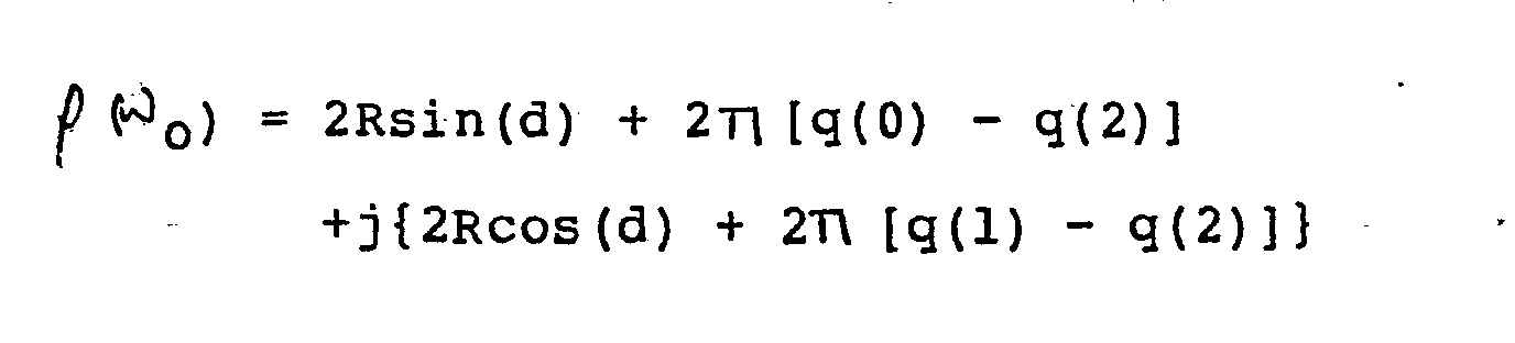
- The output of the
phase estimator stage 10 is a phase value for each of the N different sample frequencies for each of the M antennas of the array. These signals are fed to a spatialFourier series stage 12, which derives the spatial Fourier serie ρ(ω) of the phases

- Using the results set out in the annex to this specification it can be shown that the first term of this equation is 0 if M>1. When the sine factor in the second term is represented in complex exponential form, the second term can be written as :

- Again by the result given in the annex, the first component of this second term is 0 if M>2. The spatial Fourier series of the phase is thus simplified to:

- The second term of this equation can be eliminated by constraints on the array diameter as shown below.
- For the illustrated case of three antennas, the three possible values of exp(j2 m/M) are 1, (- 1 + j√3)/2 and (- 1 - j√3)/2. From equation (7), therefore, as RM/2 = 1.5R and exp(-jd) = -jsin(d) + cos(d), the spatial Fourier series of the phases can be written out as:


- The modulo π operation is defined such that the result is in the range - π/2 to + π/2 and similarly for the modulo √3π operation. Therefore the modulo π and 3Ti operations effectively eliminate terms including the q(m) terms. The four quadrant inverse tangent of the ratio of the real and imaginary parts taken to modulo T7 and modulo √3π respectively yields an accurate, unique and unambiguous estimate of the bearing information d. The restriction that R < π/3 where R=r ωo/c is equivalent to constraining the array diameter 2r to be less than one third of a wavelength at the highest frequency of interest. The actual bearing of the signal source at ωo is calculated from b = (D/2) - d.
- For an array of four antennas the four possible values of exp(j2π m/M) are l,j,- 1 and - j, consequently the imaginary component of the second term in equation (7) can only have values which are integer multiples of 2 including 0. Now, if the value of RM/2 = 2R is constrained to be less than , then taking the real and imaginary parts of ρ (ωo) modulo 2π will in effect eliminate the q(m) dependent terms and yield a unique and unambiguous bearing estimate. Therefore equation (7) becomes :
- With 2R constrained to be less than π , the real part of ρ (ωo) modulo 2π = 2Rsin(d) and the imaginary part of ρ (ωo) modulo 2π = 2Rcos(d), so that a four quadrant inverse tangent operation on the ratio of the real and imaginary parts then yields the wanted bearing information d from which the bearing b is derived as b=( π/2) - d. The constraint R<π/2 implies that the array diameter (2r) must be less than half a wavelength at the highest frequency of interest.
- Reviewing the above, in the illustrated embodiment with M = 3, the spatial
Fourier series stage 12 takes the Fourier series of the phases for each of the N sample frequencies and then computes the arctan of the ratio of the real and imaginary parts of the Fourier series modulo η and √3π respectively and outputs the estimated bearing as π/2 minus the calculated arctan. - This bearing information output from the spatial
Fourier series stage 12 and amplitude information derived by taking the magnitude of E(m,ω ) at the complex spectrum analysis stage 8 for each sample frequency are then fed to a final output and display stage 14. This final stage 14 analyses the results obtained for the N sample frequencies to determine at which frequency signals are being received. For example, by outputting the bearing information b calculated for amplitudes of over a predetermined threshold value. However, when a received signal has a frequency intermediate between two of the sample frequencies, the calculated bearing for each of the adjacent sample frequencies will be substantially identical but the amplitudes will be reduced, in the worst case to half the true amplitude. Therefore, it may be necessary to introduce more complex criteria for selecting which bearing information to display together with an estimate of the frequency of the source at that bearing. The complexity of the analysis carried out at the final output stage depends upon the application to which the system is to be put. In its simplest form, the output stage 14 can display frequency, bearing and amplitude for each of the N sample frequencies, so that the operator can himself determine the likelihood of signals at or close to these sample frequencies. - With suitable limitations on the array diameter, the present analysis can also be employed for circular arrays of five to eight antennas. However, in each case the array is constrained to be of smaller diameter than the cases for either three or four antennas and is therefore more liable to errors as the phases of the signals will be relatively closer.
- With the use of arrays of larger diameter than the limits set out above, it is also possible to use the above-described system. However, because of the q(m) term the output will include ambiguous bearings as well as the correct values. In certain circumstances these ambiguous bearings can be eliminated from the results for example, if the possible range of bearing values is known within limits.
- The present DF system could also be used in narrow and wide aperture form, where a narrow aperture system is one which has an array diameter falling within the required constraints for an accurate and unambiguous bearing output. The bearing information from the narrow aperture system can then be used to eliminate ambiguous bearing values from the output of the wide aperture system to produce bearing outputs which are less sensitive to reception errors.
- It is desired to show that


Claims (5)
Applications Claiming Priority (2)
| Application Number | Priority Date | Filing Date | Title |
|---|---|---|---|
| GB08326912A GB2147760B (en) | 1983-10-07 | 1983-10-07 | Direction finding systems |
| GB8326912 | 1983-10-07 |
Publications (3)
| Publication Number | Publication Date |
|---|---|
| EP0137745A2 true EP0137745A2 (en) | 1985-04-17 |
| EP0137745A3 EP0137745A3 (en) | 1986-05-14 |
| EP0137745B1 EP0137745B1 (en) | 1989-11-15 |
Family
ID=10549849
Family Applications (1)
| Application Number | Title | Priority Date | Filing Date |
|---|---|---|---|
| EP84306249A Expired EP0137745B1 (en) | 1983-10-07 | 1984-09-12 | Direction finding systems |
Country Status (4)
| Country | Link |
|---|---|
| US (1) | US4626859A (en) |
| EP (1) | EP0137745B1 (en) |
| DE (1) | DE3480497D1 (en) |
| GB (1) | GB2147760B (en) |
Cited By (11)
| Publication number | Priority date | Publication date | Assignee | Title |
|---|---|---|---|---|
| WO1999065251A3 (en) * | 1998-06-09 | 2000-02-24 | Kwang Hwan Lee | Apparatus and method for detecting calling location of radio signal using short pulse |
| RU2158001C1 (en) * | 1999-12-06 | 2000-10-20 | 5 Центральный научно-исследовательский испытательный институт Министерства обороны Российской Федерации | Method for radio direction-finding |
| RU2262119C1 (en) * | 2004-03-24 | 2005-10-10 | Федеральное государственное унитарное предприятие "Воронежский научно-исследовательский институт связи" | Method for direction finding of radio signals |
| RU2263927C2 (en) * | 2004-01-14 | 2005-11-10 | Открытое акционерное общество "Корпорация "Фазотрон-Научно-исследовательский институт радиостроения" | Method of evaluating parameters of trajectory of radio-frequency radiation sources in two-positioned passive goniometrical radar station |
| RU2267134C2 (en) * | 2003-12-03 | 2005-12-27 | Федеральное государственное унитарное предприятие "Ростовский-на-Дону научно-исследовательский институт радиосвязи" | Mode of direction finding of radio signals and a direction finder of radio signals |
| RU2316015C1 (en) * | 2006-06-29 | 2008-01-27 | Закрытое акционерное общество "Научно-производственное предприятие "Бриг" (ЗАО "НПП "Бриг") | Method for computer-interferometer localization of complex signals |
| CN104049234A (en) * | 2014-03-18 | 2014-09-17 | 电子科技大学 | Method for adopting uniform circular arrays to quickly determine spatial spectrums |
| RU2598648C1 (en) * | 2015-04-01 | 2016-09-27 | Федеральное государственное казенное военное образовательное учреждение высшего профессионального образования "Военный учебно-научный центр Военно-воздушных сил "Военно-воздушная академия имени профессора Н.Е. Жуковского и Ю.А. Гагарина" (г. Воронеж) Министерства обороны Российской Федерации | Method for radio direction-finding and radio direction finder therefor |
| CN109444811A (en) * | 2018-11-09 | 2019-03-08 | 电子科技大学成都学院 | Array df method and device |
| RU2736414C1 (en) * | 2019-05-28 | 2020-11-17 | Федеральное государственное казенное военное образовательное учреждение высшего образования "Военный учебно-научный центр Военно-Морского Флота "Военно-морская академия им. Адмирала Флота Советского Союза Н.Г. Кузнецова" | Method of spatial filtering of signals |
| EP3745155A1 (en) * | 2019-05-29 | 2020-12-02 | Assa Abloy AB | Determining a position of a mobile key device based on phase difference of samples |
Families Citing this family (56)
| Publication number | Priority date | Publication date | Assignee | Title |
|---|---|---|---|---|
| GB2189363A (en) * | 1986-04-18 | 1987-10-21 | Philips Electronic Associated | Radio direction-finding |
| US4845502A (en) * | 1988-04-07 | 1989-07-04 | Carr James L | Direction finding method and apparatus |
| US4975710A (en) * | 1989-08-01 | 1990-12-04 | Baghdady Elie J | Methods and apparatus for direction of arrival measurement and radio navigation aids |
| US5515378A (en) * | 1991-12-12 | 1996-05-07 | Arraycomm, Inc. | Spatial division multiple access wireless communication systems |
| US5625880A (en) * | 1991-12-12 | 1997-04-29 | Arraycomm, Incorporated | Spectrally efficient and high capacity acknowledgement radio paging system |
| US5583517A (en) * | 1992-08-20 | 1996-12-10 | Nexus 1994 Limited | Multi-path resistant frequency-hopped spread spectrum mobile location system |
| US5708971A (en) * | 1994-01-11 | 1998-01-13 | Ericsson Inc. | Two-way paging system and apparatus |
| US5592181A (en) * | 1995-05-18 | 1997-01-07 | Hughes Aircraft Company | Vehicle position tracking technique |
| US5568154A (en) * | 1995-05-22 | 1996-10-22 | State Of Israel-Ministry Of Defense Armament Development Authority-Rafael | System and a method for the instantaneous determination of the frequencies and angles of arrival of simultaneously incoming RF signals |
| AU683802B1 (en) * | 1996-09-30 | 1997-11-20 | Telasic Communications, Inc. | Vehicle position tracking technique |
| US6463295B1 (en) | 1996-10-11 | 2002-10-08 | Arraycomm, Inc. | Power control with signal quality estimation for smart antenna communication systems |
| US6275543B1 (en) | 1996-10-11 | 2001-08-14 | Arraycomm, Inc. | Method for reference signal generation in the presence of frequency offsets in a communications station with spatial processing |
| US7035661B1 (en) | 1996-10-11 | 2006-04-25 | Arraycomm, Llc. | Power control with signal quality estimation for smart antenna communication systems |
| DE19744692A1 (en) * | 1997-10-10 | 1999-04-15 | Daimler Benz Aerospace Ag | DF method for determining the direction of incidence of a high-frequency electromagnetic signal |
| US7299071B1 (en) | 1997-12-10 | 2007-11-20 | Arraycomm, Llc | Downlink broadcasting by sequential transmissions from a communication station having an antenna array |
| JP2988463B2 (en) * | 1998-03-24 | 1999-12-13 | 日本電気株式会社 | Direction finding device and measurement result processing device therefor |
| US6615024B1 (en) | 1998-05-01 | 2003-09-02 | Arraycomm, Inc. | Method and apparatus for determining signatures for calibrating a communication station having an antenna array |
| SE512219C2 (en) * | 1998-06-15 | 2000-02-14 | Jan Bergman | Method and system for obtaining direction for an elliptically polarized electromagnetic wave propagation |
| RU2192651C2 (en) * | 1998-07-02 | 2002-11-10 | Войсковая часть 11135 | Procedure of direction finding of signal source |
| GB2346753A (en) * | 1998-10-21 | 2000-08-16 | Rnli | Direction finding aerials |
| NL1010657C1 (en) * | 1998-11-26 | 2000-05-30 | Hollandse Signaalapparaten Bv | Array antenna and method for operating an array antenna. |
| RU2150122C1 (en) * | 1999-04-06 | 2000-05-27 | Государственное конструкторское бюро аппаратно-программных систем "Связь" | Method for taking two-dimensional bearing and detection frequency of radio sources |
| RU2151406C1 (en) * | 1999-04-27 | 2000-06-20 | Государственное конструкторское бюро аппаратно-программных систем "Связь" | Process determining structure of communication systems |
| US6600914B2 (en) | 1999-05-24 | 2003-07-29 | Arraycomm, Inc. | System and method for emergency call channel allocation |
| US6141567A (en) | 1999-06-07 | 2000-10-31 | Arraycomm, Inc. | Apparatus and method for beamforming in a changing-interference environment |
| US7139592B2 (en) | 1999-06-21 | 2006-11-21 | Arraycomm Llc | Null deepening for an adaptive antenna based communication station |
| US6985466B1 (en) | 1999-11-09 | 2006-01-10 | Arraycomm, Inc. | Downlink signal processing in CDMA systems utilizing arrays of antennae |
| US6795409B1 (en) | 2000-09-29 | 2004-09-21 | Arraycomm, Inc. | Cooperative polling in a wireless data communication system having smart antenna processing |
| US7062294B1 (en) | 2000-09-29 | 2006-06-13 | Arraycomm, Llc. | Downlink transmission in a wireless data communication system having a base station with a smart antenna system |
| US6982968B1 (en) | 2000-09-29 | 2006-01-03 | Arraycomm, Inc. | Non-directional transmitting from a wireless data base station having a smart antenna system |
| US6437741B1 (en) | 2001-01-10 | 2002-08-20 | Itt Manufacturing Enterprises, Inc. | Detection of emissions from commercial electronic devices that include an amplitude modulation component |
| RU2236021C1 (en) * | 2002-12-15 | 2004-09-10 | 5 Центральный научно-исследовательский испытательный институт Министерства обороны Российской Федерации | Radio-frequency emission identification method |
| EP2977783B1 (en) | 2003-04-10 | 2020-06-24 | Leonardo Mw Ltd | Interferometers |
| RU2263327C1 (en) * | 2004-01-15 | 2005-10-27 | Терентьев Алексей Васильевич | Method for radio signals position-finding and direction-finder for realization of said method |
| JP3841100B2 (en) * | 2004-07-06 | 2006-11-01 | セイコーエプソン株式会社 | Electronic device and wireless communication terminal |
| RU2276381C1 (en) * | 2004-12-01 | 2006-05-10 | Открытое акционерное общество "Воронежское центральное конструкторское бюро "Полюс" (ОАО "ВЦКБ "Полюс") | Radio bearing indicator for detecting two-dimensional bearing |
| RU2288481C2 (en) * | 2005-01-11 | 2006-11-27 | 5 Центральный научно-исследовательский испытательный институт Министерства обороны Российской Федерации (5 ЦНИИИ МО РФ) | Method for determining two-dimensional bearing |
| RU2289146C9 (en) * | 2005-02-21 | 2007-01-20 | Открытое акционерное общество "Воронежское центральное конструкторское бюро "Полюс" (ОАО "ВЦКБ "Полюс") | Method for detection and direction finding of radio signals |
| RU2321014C2 (en) * | 2005-09-12 | 2008-03-27 | Федеральное государственное унитарное предприятие "Воронежский научно-исследовательский институт связи" | Mode of direction finding and multi channel direction finder |
| US7576686B2 (en) * | 2006-08-07 | 2009-08-18 | Garmin International, Inc. | Method and system for calibrating an antenna array for an aircraft surveillance system |
| US7439901B2 (en) * | 2006-08-08 | 2008-10-21 | Garmin International, Inc. | Active phased array antenna for aircraft surveillance systems |
| US20080055150A1 (en) * | 2006-09-06 | 2008-03-06 | Garmin International, Inc. | Method and system for detecting and decoding air traffic control reply signals |
| WO2008084037A1 (en) * | 2007-01-09 | 2008-07-17 | Selex Sensors & Airborne Systems Ltd. | Emitter location |
| US7825858B2 (en) | 2007-02-28 | 2010-11-02 | Garmin International, Inc. | Methods and systems for frequency independent bearing detection |
| US20080284637A1 (en) * | 2007-02-28 | 2008-11-20 | Garmin International, Inc. | Digital tas transmitter and receiver systems and methods |
| RU2407026C1 (en) * | 2009-06-26 | 2010-12-20 | Государственное образовательное учреждение высшего профессионального образования Московский авиационный институт (государственный технический университет) (МАИ) | Location finding method of narrow-band radio signals of short-wave range |
| CN102792177B (en) * | 2010-01-18 | 2014-10-01 | 张登科 | Method for direction finding |
| RU2452974C1 (en) * | 2011-03-03 | 2012-06-10 | Федеральное государственное военное образовательное учреждение высшего профессионального образования "Военный авиационный инженерный университет" (г. Воронеж) Министерства обороны Российской Федерации | Method of determining angular spectrum |
| RU2528177C2 (en) * | 2012-12-28 | 2014-09-10 | Федеральное государственное бюджетное образовательное учреждение высшего профессионального образования "Московский государственный технический университет имени Н.Э. Баумана" (МГТУ им. Н.Э. Баумана) | Method of determining bearing panorama of radio-frequency sources at one frequency |
| RU2530748C2 (en) * | 2012-12-28 | 2014-10-10 | Федеральное государственное бюджетное образовательное учреждение высшего профессионального образования "Московский государственный технический университет имени Н.Э. Баумана" (МГТУ им. Н.Э. Баумана) | Method of determining most probable values of bearings of radio-frequency sources at one frequency |
| RU2535174C1 (en) * | 2013-10-18 | 2014-12-10 | Закрытое акционерное общество "ИРКОС" | Method of two-dimensional direction finding of air object |
| RU2551115C1 (en) * | 2013-12-30 | 2015-05-20 | Федеральное государственное бюджетное образовательное учреждение высшего профессионального образования "Московский государственный технический университет имени Н.Э. Баумана" (МГТУ им. Н.Э. Баумана) | Method of characteristics determination of overlapping radiosignals of same frequency |
| US10177451B1 (en) | 2014-08-26 | 2019-01-08 | Ball Aerospace & Technologies Corp. | Wideband adaptive beamforming methods and systems |
| RU2599257C1 (en) * | 2015-11-30 | 2016-10-10 | Борис Николаевич Горевич | Method of radio signals spatial processing |
| RU2620130C1 (en) * | 2016-03-28 | 2017-05-23 | Федеральное государственное казенное военное образовательное учреждение высшего образования "Военный учебно-научный центр Военно-воздушных сил "Военно-воздушная академия имени профессора Н.Е. Жуковского и Ю.А. Гагарина" (г. Воронеж) Министерства обороны Российской Федерации | Method of amplitude two-dimensional direction-finding bearing |
| RU2663182C1 (en) * | 2017-08-02 | 2018-08-02 | Общество с ограниченной ответственностью "ОКБ "Эланор" | Automatic independent air observation system in the far navigation zone |
Family Cites Families (21)
| Publication number | Priority date | Publication date | Assignee | Title |
|---|---|---|---|---|
| FR1605544A (en) * | 1961-12-28 | 1979-06-29 | ||
| DE1198424B (en) * | 1964-04-30 | 1965-08-12 | Telefunken Patent | Arrangement for determining the direction of incidence and the elevation angle of an electric wave |
| US3339204A (en) * | 1965-03-03 | 1967-08-29 | Motorola Inc | Electronic system |
| DE2113857C3 (en) * | 1971-03-23 | 1979-10-04 | Licentia Patent-Verwaltungs-Gmbh, 6000 Frankfurt | Method for determining the amplitude and / or the direction of incidence of two RF oscillations of different frequencies that occur in a communication channel |
| DE2113883C2 (en) * | 1971-03-23 | 1982-09-30 | Licentia Patent-Verwaltungs-Gmbh, 6000 Frankfurt | DF method |
| US3848254A (en) * | 1971-07-28 | 1974-11-12 | Siemens Ag | Method for locating vehicles |
| DE2159977A1 (en) * | 1971-12-03 | 1973-06-07 | Krupp Gmbh | SWITCHING ARRANGEMENT FOR DETERMINING THE DIRECTION OF INCIDENT WAVE ENERGY, IN PARTICULAR SOUND WAVES, USING A GRADIENT SEPARATION SYSTEM |
| US3792472A (en) * | 1972-08-14 | 1974-02-12 | Bendix Corp | Warning indicator to alert aircraft pilot to presence and bearing of other aircraft |
| DE2242790B2 (en) * | 1972-08-31 | 1976-10-21 | Hißen, Helmut, Dr.-Ing., 5481 Nierendorf; Kosel, Georg, Dr.-Ing., 5483 Bad Neuenahr; Krätzig, Gudrun, 5300 Bonn-Bad Godesberg | DIGITAL RECEIVER WITH SPECTRUM EVALUATION |
| DE2328720B2 (en) * | 1973-06-06 | 1975-10-02 | Licentia Patent-Verwaltungs-Gmbh, 6000 Frankfurt | Direction finder |
| US3887923A (en) * | 1973-06-26 | 1975-06-03 | Us Navy | Radio-frequency holography |
| DE2358585C3 (en) * | 1973-11-24 | 1979-11-15 | Standard Elektrik Lorenz Ag, 7000 Stuttgart | Radio direction finder and radio beacon working according to the reciprocity law |
| GB1598325A (en) * | 1976-04-28 | 1981-09-16 | Plessey Co Ltd | Direction finding arrangements |
| GB1536996A (en) * | 1977-03-25 | 1978-12-29 | Philips Electronic Associated | Radio interferometer system |
| US4333170A (en) * | 1977-11-21 | 1982-06-01 | Northrop Corporation | Acoustical detection and tracking system |
| GB1551526A (en) * | 1978-02-16 | 1979-08-30 | Racal Ltd | Direction finding |
| GB1593286A (en) * | 1978-03-21 | 1981-07-15 | Racal Communications Equip | Direction finding |
| GB2064257B (en) * | 1978-10-13 | 1983-03-09 | Marconi Co Ltd | Radio direction finders |
| DE3017797A1 (en) * | 1980-05-09 | 1981-11-12 | Fried. Krupp Gmbh, 4300 Essen | METHOD FOR DETERMINING THE DIRECTIONS |
| GB2095497B (en) * | 1981-03-24 | 1984-08-15 | Racal Communications Equip | Improvements in and relating to direction finding |
| GB2101440A (en) * | 1981-06-20 | 1983-01-12 | Racal Res Ltd | Direction finding |
-
1983
- 1983-10-07 GB GB08326912A patent/GB2147760B/en not_active Expired
-
1984
- 1984-09-12 EP EP84306249A patent/EP0137745B1/en not_active Expired
- 1984-09-12 DE DE8484306249T patent/DE3480497D1/en not_active Expired
- 1984-09-28 US US06/655,637 patent/US4626859A/en not_active Expired - Fee Related
Cited By (14)
| Publication number | Priority date | Publication date | Assignee | Title |
|---|---|---|---|---|
| WO1999065251A3 (en) * | 1998-06-09 | 2000-02-24 | Kwang Hwan Lee | Apparatus and method for detecting calling location of radio signal using short pulse |
| RU2158001C1 (en) * | 1999-12-06 | 2000-10-20 | 5 Центральный научно-исследовательский испытательный институт Министерства обороны Российской Федерации | Method for radio direction-finding |
| RU2267134C2 (en) * | 2003-12-03 | 2005-12-27 | Федеральное государственное унитарное предприятие "Ростовский-на-Дону научно-исследовательский институт радиосвязи" | Mode of direction finding of radio signals and a direction finder of radio signals |
| RU2263927C2 (en) * | 2004-01-14 | 2005-11-10 | Открытое акционерное общество "Корпорация "Фазотрон-Научно-исследовательский институт радиостроения" | Method of evaluating parameters of trajectory of radio-frequency radiation sources in two-positioned passive goniometrical radar station |
| RU2262119C1 (en) * | 2004-03-24 | 2005-10-10 | Федеральное государственное унитарное предприятие "Воронежский научно-исследовательский институт связи" | Method for direction finding of radio signals |
| RU2316015C1 (en) * | 2006-06-29 | 2008-01-27 | Закрытое акционерное общество "Научно-производственное предприятие "Бриг" (ЗАО "НПП "Бриг") | Method for computer-interferometer localization of complex signals |
| CN104049234A (en) * | 2014-03-18 | 2014-09-17 | 电子科技大学 | Method for adopting uniform circular arrays to quickly determine spatial spectrums |
| CN104049234B (en) * | 2014-03-18 | 2017-01-25 | 电子科技大学 | Method for adopting uniform circular arrays to quickly determine spatial spectrums |
| RU2598648C1 (en) * | 2015-04-01 | 2016-09-27 | Федеральное государственное казенное военное образовательное учреждение высшего профессионального образования "Военный учебно-научный центр Военно-воздушных сил "Военно-воздушная академия имени профессора Н.Е. Жуковского и Ю.А. Гагарина" (г. Воронеж) Министерства обороны Российской Федерации | Method for radio direction-finding and radio direction finder therefor |
| CN109444811A (en) * | 2018-11-09 | 2019-03-08 | 电子科技大学成都学院 | Array df method and device |
| RU2736414C1 (en) * | 2019-05-28 | 2020-11-17 | Федеральное государственное казенное военное образовательное учреждение высшего образования "Военный учебно-научный центр Военно-Морского Флота "Военно-морская академия им. Адмирала Флота Советского Союза Н.Г. Кузнецова" | Method of spatial filtering of signals |
| EP3745155A1 (en) * | 2019-05-29 | 2020-12-02 | Assa Abloy AB | Determining a position of a mobile key device based on phase difference of samples |
| WO2020239768A1 (en) * | 2019-05-29 | 2020-12-03 | Assa Abloy Ab | Determining a position of a mobile key device based on phase difference of samples |
| US11815612B2 (en) | 2019-05-29 | 2023-11-14 | Assa Abloy Ab | Determining a position of a mobile key device based on phase difference of samples |
Also Published As
| Publication number | Publication date |
|---|---|
| EP0137745A3 (en) | 1986-05-14 |
| US4626859A (en) | 1986-12-02 |
| GB2147760B (en) | 1987-04-15 |
| EP0137745B1 (en) | 1989-11-15 |
| GB2147760A (en) | 1985-05-15 |
| DE3480497D1 (en) | 1989-12-21 |
Similar Documents
| Publication | Publication Date | Title |
|---|---|---|
| EP0137745A2 (en) | Direction finding systems | |
| US5477230A (en) | AOA application of digital channelized IFM receiver | |
| US5343212A (en) | (AOA/LBI) emitter ranging method and apparatus | |
| EP2087368B1 (en) | Method and system for detecting signal sources in a surveillance space | |
| US5526001A (en) | Precise bearings only geolocation in systems with large measurements bias errors | |
| US6147640A (en) | Communications satellite interference location system | |
| US7286085B2 (en) | Precision geolocation system and method using a long baseline interferometer antenna system | |
| US4433335A (en) | Locating device | |
| US7233285B2 (en) | Correlation interferometer geolocation | |
| US7961147B1 (en) | Long baseline phase interferometer ambiguity resolution using frequency differences | |
| US7268728B1 (en) | Moving transmitter correlation interferometer geolocation | |
| US4845502A (en) | Direction finding method and apparatus | |
| US20120139789A1 (en) | Transmitter independent techniques to extend the performance of passive coherent location | |
| US8884810B2 (en) | Compact beacon radar and full ATC services system | |
| US6169519B1 (en) | TCAS bearing measurement receiver apparatus with phase error compensation method | |
| US20120098703A1 (en) | Method for Determining Azimuth and Elevation Angles of Arrival of Coherent Sources | |
| US20050270229A1 (en) | Positioning system with a sparse antenna array | |
| US6137439A (en) | Continuous wave doppler system with suppression of ground clutter | |
| US5559515A (en) | Channel switching interferometric AMTI radar | |
| US4387376A (en) | Phase linear interferometer system and method | |
| Singh et al. | Digital receiver-based electronic intelligence system configuration for the detection and identification of intrapulse modulated radar signals | |
| US5568394A (en) | Interferometry with multipath nulling | |
| US5652590A (en) | Exploitation of emitter RF agility for unambiguous interferometer direction finding | |
| CA1159934A (en) | Cancellation of group delay error by dual speed of rotation | |
| US5321410A (en) | Adaptive doppler DF system |
Legal Events
| Date | Code | Title | Description |
|---|---|---|---|
| PUAI | Public reference made under article 153(3) epc to a published international application that has entered the european phase |
Free format text: ORIGINAL CODE: 0009012 |
|
| AK | Designated contracting states |
Designated state(s): DE GB NL |
|
| PUAL | Search report despatched |
Free format text: ORIGINAL CODE: 0009013 |
|
| AK | Designated contracting states |
Kind code of ref document: A3 Designated state(s): DE GB NL |
|
| 17P | Request for examination filed |
Effective date: 19860704 |
|
| 17Q | First examination report despatched |
Effective date: 19880506 |
|
| GRAA | (expected) grant |
Free format text: ORIGINAL CODE: 0009210 |
|
| AK | Designated contracting states |
Kind code of ref document: B1 Designated state(s): DE GB NL |
|
| REF | Corresponds to: |
Ref document number: 3480497 Country of ref document: DE Date of ref document: 19891221 |
|
| PLBI | Opposition filed |
Free format text: ORIGINAL CODE: 0009260 |
|
| 26 | Opposition filed |
Opponent name: TELEFUNKEN SYSTEMTECHNIK GMBH Effective date: 19900814 |
|
| NLR1 | Nl: opposition has been filed with the epo |
Opponent name: TELEFUNKEN SYSTEMTECHNIK GMBH |
|
| PLBN | Opposition rejected |
Free format text: ORIGINAL CODE: 0009273 |
|
| STAA | Information on the status of an ep patent application or granted ep patent |
Free format text: STATUS: OPPOSITION REJECTED |
|
| 27O | Opposition rejected |
Effective date: 19920529 |
|
| NLR2 | Nl: decision of opposition | ||
| PGFP | Annual fee paid to national office [announced via postgrant information from national office to epo] |
Ref country code: GB Payment date: 19970903 Year of fee payment: 14 |
|
| PGFP | Annual fee paid to national office [announced via postgrant information from national office to epo] |
Ref country code: DE Payment date: 19970919 Year of fee payment: 14 |
|
| PGFP | Annual fee paid to national office [announced via postgrant information from national office to epo] |
Ref country code: NL Payment date: 19970929 Year of fee payment: 14 |
|
| PG25 | Lapsed in a contracting state [announced via postgrant information from national office to epo] |
Ref country code: GB Free format text: LAPSE BECAUSE OF NON-PAYMENT OF DUE FEES Effective date: 19980912 |
|
| PG25 | Lapsed in a contracting state [announced via postgrant information from national office to epo] |
Ref country code: NL Free format text: LAPSE BECAUSE OF NON-PAYMENT OF DUE FEES Effective date: 19990401 |
|
| GBPC | Gb: european patent ceased through non-payment of renewal fee |
Effective date: 19980912 |
|
| NLV4 | Nl: lapsed or anulled due to non-payment of the annual fee |
Effective date: 19990401 |
|
| PG25 | Lapsed in a contracting state [announced via postgrant information from national office to epo] |
Ref country code: DE Free format text: LAPSE BECAUSE OF NON-PAYMENT OF DUE FEES Effective date: 19990701 |