EP0137882A1 - Bindevorrichtung für Rundballenpresse - Google Patents
Bindevorrichtung für Rundballenpresse Download PDFInfo
- Publication number
- EP0137882A1 EP0137882A1 EP83402021A EP83402021A EP0137882A1 EP 0137882 A1 EP0137882 A1 EP 0137882A1 EP 83402021 A EP83402021 A EP 83402021A EP 83402021 A EP83402021 A EP 83402021A EP 0137882 A1 EP0137882 A1 EP 0137882A1
- Authority
- EP
- European Patent Office
- Prior art keywords
- guide arm
- twine guide
- plate
- arm
- press
- Prior art date
- Legal status (The legal status is an assumption and is not a legal conclusion. Google has not performed a legal analysis and makes no representation as to the accuracy of the status listed.)
- Granted
Links
Images

Classifications
-
- A—HUMAN NECESSITIES
- A01—AGRICULTURE; FORESTRY; ANIMAL HUSBANDRY; HUNTING; TRAPPING; FISHING
- A01F—PROCESSING OF HARVESTED PRODUCE; HAY OR STRAW PRESSES; DEVICES FOR STORING AGRICULTURAL OR HORTICULTURAL PRODUCE
- A01F15/00—Baling presses for straw, hay or the like
- A01F15/08—Details
- A01F15/14—Tying devices specially adapted for baling presses
- A01F15/141—Tying devices specially adapted for baling presses for round balers
Definitions
- the present invention relates to cylindrical balers.
- presses are of a well-known general type and include sets of bands or belts which, by their displacement, form by winding inside a chamber formed in the body of the press, a ball of generally cylindrical shape from harvested products, in particular fodder or hay, picked up on the field during the progress of the press. It is usual, before unloading the cylindrical bale from the press, to ensure its binding.
- This operation which is carried out using a link generally consisting of a string, is carried out in a known manner by means of a device comprising a pivoting string guide arm or a similar member moved in a transverse movement in the sense of press run in front of the inlet of products harvested from the field.
- the string which comes from an appropriate reserve is guided by this arm generally passing inside a tube and its end is gripped by the harvested products constituting the bale at the end of the formation operation. -this, so that it is wrapped around this ball under the effect of the rotation of the latter between the strips or belts and that this winding movement is combined with a distribution of the twists of string thus formed over the length of the ball, due to the transverse sweeping movement of the arm.
- the arm is retained by locking in a stop or rest position located on one side of the machine, which generally corresponds to its end of binding position, and for the binding operation it is released and then brought quickly, for example under the action of a spring, to a starting position located on the other side of the machine, then it is moved positively in a slow sweeping movement in front of the orifice or slit of entry of the harvested products into the press, in order to bind the bale.
- the twine guide arm which is retained as previously by locking in a stop or rest position generally corresponding to the position occupied at the end of the tying operation, is when it is released positively moved in a back-and-forth movement transversely to the press, in front of the orifice or entry slit of the harvested products, thus ensuring the binding of the bale during this successive movement in both directions.
- the invention relates to devices of this second type, which thus provide for the bale a "cross" bond.
- the object of the invention is to create a simple and robust construction device, providing positive displacement of the required type, and the simplicity of which takes into account in particular the often difficult working conditions generally encountered on the field.
- the invention therefore relates to a tying device for cylindrical balers, of the type comprising a twine guide arm pivotally mounted on the press so as to be able to carry out a sweeping movement in front of the product inlet orifice. harvest in this press, this arm being supplied with twine from a reserve of twine and guiding it as far as this inlet orifice, said arm being retained in the rest position on one side of the press during training of the bale in the chamber of this press by means of a locking member, characterized in that a point on this twine guide arm or an element rigidly connected to it, spaced from the pivoting mounting point of the arm , is connected by a connecting rod or the like to a crank pin or eccentric pivot, which remains stationary during the ball forming operation in the press, and in that drive means are functionally connected to this eccentric to cause its rotation for the bale tying operation when the twine guide arm is unlocked.
- these means are arranged so as to then ensure a revolution of this eccentric, causing a back and forth movement of the twine guide arm.
- the eccentric is constituted by a plate or disc mounted for rotation and carrying an eccentric pin or pivot, this plate or disc being provided with teeth on most of its periphery but having a non-toothed peripheral sector, and the means ensuring the rotation of the plate or disk for binding include a drive member such as a pinion, a worm or the like, capable of meshing with the peripheral teeth of the plate or disk but occupying at rest a position located opposite this toothed sector.
- a drive member such as a pinion, a worm or the like
- means exert a stress on this plate or disc to bring the drive member into engagement with its teeth when the twine guide arm is unlocked for the binding operation.
- the twine guide arm is pivotally mounted at a point along its length away from its ends, thereby forming a lever with two arms, one of which is attacked by the locking member of the guide arm. -file in the rest or stop position, while the rod or the like is connected to the opposite arm of this lever formed by the twine guide arm.
- the drive member meshing with the teeth of the plate or disc mounted to rotate which as indicated above may be a pinion, a worm or the like, is judiciously driven by continuously.
- it rotates without moving the plate or disk in the rest position of the twine guide arm, that is to say when it is facing the non-toothed sector of this plate or disk, and it provides the drive in rotation of the latter as soon as an angular displacement of the latter brings its teeth into engagement with this drive member.
- the means exerting a stress on the plate or disc are judiciously constituted by an elastic member such as a spring mounted between a point of the twine guide arm or of an element rigidly connected thereto and a fixed point of the machine.
- an elastic member such as a spring mounted between a point of the twine guide arm or of an element rigidly connected thereto and a fixed point of the machine.
- the rod or the like connected to the twine guide arm is also connected to an eccentric pin or pivot of the turntable or disc, and since it is rotated substantially over 360 ° when the origin of its toothing was brought into engagement with the drive member, it results from the arrangement provided for a reciprocating movement of the twine guide arm transversely to the press which thus allows the binding of the ball by the double stroke of this arm.
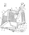
- Fig. 1 is a perspective view of a cylindrical baler of the type to which the invention is applied.
- Fig. 2 is a schematic representation of a possible embodiment of the device according to the invention.
- Fig. 3 is a detail view.
- the press shown in FIG. 1 comprises in a known manner a body 1 comprising a fixed part 2 mounted on a chassis 3 supported by wheels 4 and at the upper end of which is articulated a rear door 5.
- the assembly is intended to be coupled to a tractor (not shown) by means of a coupling arrow 6.
- a tractor not shown
- the press is moved across the field, the crop products resting on the ground are picked up by means of a pickup 7 and brought to a formation chamber d 'A ball, which is formed in the body 1 of the press between sets of belts or bands 8 passing over guide and tension rollers 9.
- the drive of the movable members of the press is ensured by means of a shaft 10 which is intended to be connected to the PTO shaft of the tractor.
- the bale When the bale has reached the required diameter, it is subjected in the press chamber to a tying operation, in a manner known per se, using a device (not visible in Fig. 1) housed in the front part 11 of the press body, by means of a twine taken from a twine box 12 and brought to a twine guide arm pivotally mounted, - one end of which undergoes, for tying, a movement of sweeping transversely to the press, in front of the inlet for the crop products therein. The tied bale is then discharged by opening the rear door 5 of the press.
- FIG. 2 There is shown schematically in FIG. 2 an embodiment of the device which is the subject of the invention for controlling the movement of the twine guide arm in front of the inlet of the crop products in the press.
- the twine guide arm has been shown diagrammatically at 13.
- This arm is conventionally constituted at least in part by a tube (as visible in Fig. 3) through which passes the string F intended for tying the bale.
- This twine leaves the tubular part of the twine guide arm at the end 14 thereof.
- the twine guide arm 13 is pivotally mounted on the body or chassis of the press at 15, at a point located along its length.
- the end 16 of the twine guide arm opposite its end 14 of the twine outlet is connected by a link 17 to an eccentric pin or pivot 18 of a plate or disc 19 rotatably mounted around its axis 20 in any suitable manner.
- this plate or disc 19 is provided over most of its periphery with toothing 21, but it has a sector 22 without toothing extending over a length of arc of small value.
- an endless screw carried by a shaft 24 which is driven in continuous rotation during the work of the press, from the shaft 10 thereof.
- the twine guide arm 13 is subjected to the stress of a tension spring 25, which is connected by one end to the end 16 of the twine guide arm and by its other end to a fixed point of the press at 26.
- a tension spring 25 which is connected by one end to the end 16 of the twine guide arm and by its other end to a fixed point of the press at 26. The role of this spring will be indicated later.
- FIG. 2 There is shown in solid lines in FIG. 2 the rest position of the twine guide arm 13. It can be seen that this arm is held in this rest position in a usual manner in itself by means of a locking member constituted by a lever 27 pivotally mounted at 28 ( Fig. 3) and provided at one end with a spout 29 which locks the twine guide arm 13 in its rest or stop position, the lever 27 itself being returned and held in this position by means of a spring 30.
- 31 diagrammatically at 31 (FIG. 3) a cord which can be actuated manually by the operator of the press at the end of the binding operation, or else which can be moved automatically, in a manner known per se in this technique, in order to free the twine guide arm to effect the binding.
- Also indicated at 32 is a knife associated with an anvil 33, which in the rest position of the twine guide arm, retains the end of the twine F, and which can be actuated to cut the tying twine at the end of the binding operation, by means of a lever 34 connected to this knife 32 with the interposition of a spring 35 and actuated by the twine guide arm 13 when it returns to the rest position, a manner known per se in this technique.
- the invention relates more specifically to the mode of control of the twine guide arm 13 for binding, and the operation of the device which is the subject of the invention will now be described.
- the spring 25 ' acts on the end 16 of this twine guide arm to tend to move it anti-clockwise around its pivot axis 15.
- the rod 17 working in compression, transmits a force to the eccentric pivot 18 of the plate or disc 19, by stretching thus moving this plate over an angle of small value in the direction indicated by the arrow 36. This brings the origin of the toothing 21 of the plate or disk 19 in engagement with the worm 23, and the plate or disk 19 is thus driven in rotation about its axis 20.
- twine guide arm 13 When the twine guide arm 13 approaches its end position, which is the position shown in solid lines in FIG. 2, it acts first on the lever 34, to cut the string F by means of the knife 32, which will retain the end of the string in the usual manner. It then engages behind the spout 29 of the locking lever 27, by which it will then be retained in the rest or stop position. In this position, the non-toothed sector 22 of the plate or disk 19 has returned to be placed opposite the worm 23, so that the drive of this plate or disk is interrupted.
- the device which is the subject of the invention thus makes it possible to obtain in a simple manner a reciprocating scanning command for the twine guide arm 13 for the purpose of the binding operation.
Landscapes
- Life Sciences & Earth Sciences (AREA)
- Environmental Sciences (AREA)
- Basic Packing Technique (AREA)
- Harvester Elements (AREA)
Priority Applications (3)
| Application Number | Priority Date | Filing Date | Title |
|---|---|---|---|
| DE8383402021T DE3376091D1 (en) | 1983-10-18 | 1983-10-18 | Wrapping mechanism for a roto baler |
| DE1983402021 DE137882T1 (de) | 1983-10-18 | 1983-10-18 | Bindevorrichtung fuer rundballenpresse. |
| EP19830402021 EP0137882B1 (de) | 1983-10-18 | 1983-10-18 | Bindevorrichtung für Rundballenpresse |
Applications Claiming Priority (1)
| Application Number | Priority Date | Filing Date | Title |
|---|---|---|---|
| EP19830402021 EP0137882B1 (de) | 1983-10-18 | 1983-10-18 | Bindevorrichtung für Rundballenpresse |
Publications (2)
| Publication Number | Publication Date |
|---|---|
| EP0137882A1 true EP0137882A1 (de) | 1985-04-24 |
| EP0137882B1 EP0137882B1 (de) | 1988-03-30 |
Family
ID=8191452
Family Applications (1)
| Application Number | Title | Priority Date | Filing Date |
|---|---|---|---|
| EP19830402021 Expired EP0137882B1 (de) | 1983-10-18 | 1983-10-18 | Bindevorrichtung für Rundballenpresse |
Country Status (2)
| Country | Link |
|---|---|
| EP (1) | EP0137882B1 (de) |
| DE (2) | DE3376091D1 (de) |
Cited By (3)
| Publication number | Priority date | Publication date | Assignee | Title |
|---|---|---|---|---|
| US4885990A (en) * | 1986-10-10 | 1989-12-12 | Rivierre Casalis | Control of twine guide arm in a pickup baler |
| US4998469A (en) * | 1990-04-23 | 1991-03-12 | Ford New Holland, Inc. | Method of wrapping bales with twine |
| US5054387A (en) * | 1990-04-23 | 1991-10-08 | Ford New Holland, Inc. | Apparatus for wrapping bales with twine |
Citations (4)
| Publication number | Priority date | Publication date | Assignee | Title |
|---|---|---|---|---|
| US2850964A (en) * | 1955-09-12 | 1958-09-09 | Allis Chalmers Mfg Co | Rotary baler |
| GB2018192A (en) * | 1978-04-07 | 1979-10-17 | Sperry Rand Corp | Crop roll forming machines with wrapping mechanisms for binding crop rolls |
| FR2446065A1 (fr) * | 1979-01-11 | 1980-08-08 | Pomar Goma Jose Maria | Dispositif distributeur de fil de ligature autour de balles de paille ou fourrage formees dans une presse rotative |
| EP0064113A1 (de) * | 1981-05-06 | 1982-11-10 | JOHN DEERE (Société Anonyme) | Binderbetätigungseinrichtung für Rundballenpresse |
-
1983
- 1983-10-18 DE DE8383402021T patent/DE3376091D1/de not_active Expired
- 1983-10-18 EP EP19830402021 patent/EP0137882B1/de not_active Expired
- 1983-10-18 DE DE1983402021 patent/DE137882T1/de active Pending
Patent Citations (4)
| Publication number | Priority date | Publication date | Assignee | Title |
|---|---|---|---|---|
| US2850964A (en) * | 1955-09-12 | 1958-09-09 | Allis Chalmers Mfg Co | Rotary baler |
| GB2018192A (en) * | 1978-04-07 | 1979-10-17 | Sperry Rand Corp | Crop roll forming machines with wrapping mechanisms for binding crop rolls |
| FR2446065A1 (fr) * | 1979-01-11 | 1980-08-08 | Pomar Goma Jose Maria | Dispositif distributeur de fil de ligature autour de balles de paille ou fourrage formees dans une presse rotative |
| EP0064113A1 (de) * | 1981-05-06 | 1982-11-10 | JOHN DEERE (Société Anonyme) | Binderbetätigungseinrichtung für Rundballenpresse |
Cited By (3)
| Publication number | Priority date | Publication date | Assignee | Title |
|---|---|---|---|---|
| US4885990A (en) * | 1986-10-10 | 1989-12-12 | Rivierre Casalis | Control of twine guide arm in a pickup baler |
| US4998469A (en) * | 1990-04-23 | 1991-03-12 | Ford New Holland, Inc. | Method of wrapping bales with twine |
| US5054387A (en) * | 1990-04-23 | 1991-10-08 | Ford New Holland, Inc. | Apparatus for wrapping bales with twine |
Also Published As
| Publication number | Publication date |
|---|---|
| EP0137882B1 (de) | 1988-03-30 |
| DE137882T1 (de) | 1985-09-26 |
| DE3376091D1 (en) | 1988-05-05 |
Similar Documents
| Publication | Publication Date | Title |
|---|---|---|
| EP0192904B1 (de) | Rundballenpresse mit Bindemechanismus | |
| EP0046427B1 (de) | Bindeeinrichtung für Rundballenpressen | |
| FR2549688A1 (fr) | Machine pour ramasser et former en balles rondes des matieres fibreuses disposees en andains | |
| FR2555858A1 (fr) | Dispositif pour former des balles de vegetaux | |
| EP0046426B1 (de) | Rundballenpresse | |
| EP0228944B1 (de) | Vorrichtung für die Bildung von Rundballen von Futter in einer Rundballenpresse | |
| EP0090120B1 (de) | Bindevorrichtung mittels zwei Bindfäden für Rundballenpresse | |
| EP1322148A1 (de) | Vorrichtung für die selbsttätige anlage von verdrillten bändern | |
| EP0267821B1 (de) | Verfahren und Vorrichtung zum Steuern von Schnurführungsarmen zum Binden von Rollballen in einer Rollballenpresse | |
| EP0041442B1 (de) | Bindevorrichtung für eine Rundballenpresse | |
| EP0130258A1 (de) | Rollballenpresse | |
| EP0137882B1 (de) | Bindevorrichtung für Rundballenpresse | |
| EP0041444B1 (de) | Bindevorrichtung für Rundballenpresse | |
| EP0085817B1 (de) | Zweiarmige Bindevorrichtung für Rundballenpresse | |
| FR2604856A1 (fr) | Presse a grosses balles pour produits de recoltes agricoles | |
| BE1004440A3 (fr) | Presse destinee a la formation de balles rondes de produit de moissonnage agricole. | |
| EP0057122B1 (de) | Bindevorrichtung für Rundballenpressen | |
| EP0059815B1 (de) | Bindegarnsteuerung für eine Rundballenpresse | |
| EP0217714B1 (de) | Verfahren und Vorrichtung zum Binden von Ballen aus faserigem Erntegut | |
| EP0064113B1 (de) | Binderbetätigungseinrichtung für Rundballenpresse | |
| FR2489088A1 (fr) | Dispositif pour degager un noeud de la pince noueuse dans des machines agricoles, notamment des presses a faire des balles | |
| EP0071687B1 (de) | Bindevorrichtung für Rundballenpressen | |
| EP0041443B1 (de) | Bindevorrichtung für Rundballenpresse | |
| FR2498048A1 (fr) | Dispositif de liage pour presses a balles cylindriques | |
| FR2500995A1 (fr) | Nouvelle presse enrouleuse pour balles rondes de fourrage ou de paille |
Legal Events
| Date | Code | Title | Description |
|---|---|---|---|
| PUAI | Public reference made under article 153(3) epc to a published international application that has entered the european phase |
Free format text: ORIGINAL CODE: 0009012 |
|
| AK | Designated contracting states |
Designated state(s): DE FR GB IT NL |
|
| ITCL | It: translation for ep claims filed |
Representative=s name: LENZI & C. |
|
| TCNL | Nl: translation of patent claims filed | ||
| DET | De: translation of patent claims | ||
| 17P | Request for examination filed |
Effective date: 19850928 |
|
| 17Q | First examination report despatched |
Effective date: 19860528 |
|
| ITF | It: translation for a ep patent filed | ||
| GRAA | (expected) grant |
Free format text: ORIGINAL CODE: 0009210 |
|
| AK | Designated contracting states |
Kind code of ref document: B1 Designated state(s): DE FR GB IT NL |
|
| REF | Corresponds to: |
Ref document number: 3376091 Country of ref document: DE Date of ref document: 19880505 |
|
| GBT | Gb: translation of ep patent filed (gb section 77(6)(a)/1977) | ||
| PG25 | Lapsed in a contracting state [announced via postgrant information from national office to epo] |
Ref country code: GB Effective date: 19881018 |
|
| PLBE | No opposition filed within time limit |
Free format text: ORIGINAL CODE: 0009261 |
|
| STAA | Information on the status of an ep patent application or granted ep patent |
Free format text: STATUS: NO OPPOSITION FILED WITHIN TIME LIMIT |
|
| 26N | No opposition filed | ||
| PG25 | Lapsed in a contracting state [announced via postgrant information from national office to epo] |
Ref country code: NL Effective date: 19890501 |
|
| NLV4 | Nl: lapsed or anulled due to non-payment of the annual fee | ||
| PG25 | Lapsed in a contracting state [announced via postgrant information from national office to epo] |
Ref country code: FR Free format text: LAPSE BECAUSE OF NON-PAYMENT OF DUE FEES Effective date: 19890630 |
|
| PG25 | Lapsed in a contracting state [announced via postgrant information from national office to epo] |
Ref country code: DE Effective date: 19890701 |
|
| GBPC | Gb: european patent ceased through non-payment of renewal fee | ||
| REG | Reference to a national code |
Ref country code: FR Ref legal event code: ST |