EP0137888A2 - Dispositif de moulage par injection - Google Patents
Dispositif de moulage par injection Download PDFInfo
- Publication number
- EP0137888A2 EP0137888A2 EP84103278A EP84103278A EP0137888A2 EP 0137888 A2 EP0137888 A2 EP 0137888A2 EP 84103278 A EP84103278 A EP 84103278A EP 84103278 A EP84103278 A EP 84103278A EP 0137888 A2 EP0137888 A2 EP 0137888A2
- Authority
- EP
- European Patent Office
- Prior art keywords
- heating
- nozzle
- insulating
- heating tube
- tube
- Prior art date
- Legal status (The legal status is an assumption and is not a legal conclusion. Google has not performed a legal analysis and makes no representation as to the accuracy of the status listed.)
- Granted
Links
Images





Classifications
-
- B—PERFORMING OPERATIONS; TRANSPORTING
- B29—WORKING OF PLASTICS; WORKING OF SUBSTANCES IN A PLASTIC STATE IN GENERAL
- B29C—SHAPING OR JOINING OF PLASTICS; SHAPING OF MATERIAL IN A PLASTIC STATE, NOT OTHERWISE PROVIDED FOR; AFTER-TREATMENT OF THE SHAPED PRODUCTS, e.g. REPAIRING
- B29C45/00—Injection moulding, i.e. forcing the required volume of moulding material through a nozzle into a closed mould; Apparatus therefor
- B29C45/17—Component parts, details or accessories; Auxiliary operations
- B29C45/26—Moulds
- B29C45/27—Sprue channels ; Runner channels or runner nozzles
- B29C45/30—Flow control means disposed within the sprue channel, e.g. "torpedo" construction
-
- B—PERFORMING OPERATIONS; TRANSPORTING
- B29—WORKING OF PLASTICS; WORKING OF SUBSTANCES IN A PLASTIC STATE IN GENERAL
- B29C—SHAPING OR JOINING OF PLASTICS; SHAPING OF MATERIAL IN A PLASTIC STATE, NOT OTHERWISE PROVIDED FOR; AFTER-TREATMENT OF THE SHAPED PRODUCTS, e.g. REPAIRING
- B29C45/00—Injection moulding, i.e. forcing the required volume of moulding material through a nozzle into a closed mould; Apparatus therefor
- B29C45/17—Component parts, details or accessories; Auxiliary operations
- B29C45/26—Moulds
- B29C45/27—Sprue channels ; Runner channels or runner nozzles
- B29C45/2737—Heating or cooling means therefor
-
- B—PERFORMING OPERATIONS; TRANSPORTING
- B29—WORKING OF PLASTICS; WORKING OF SUBSTANCES IN A PLASTIC STATE IN GENERAL
- B29C—SHAPING OR JOINING OF PLASTICS; SHAPING OF MATERIAL IN A PLASTIC STATE, NOT OTHERWISE PROVIDED FOR; AFTER-TREATMENT OF THE SHAPED PRODUCTS, e.g. REPAIRING
- B29C45/00—Injection moulding, i.e. forcing the required volume of moulding material through a nozzle into a closed mould; Apparatus therefor
- B29C45/17—Component parts, details or accessories; Auxiliary operations
- B29C45/26—Moulds
- B29C45/27—Sprue channels ; Runner channels or runner nozzles
- B29C45/2737—Heating or cooling means therefor
- B29C2045/2743—Electrical heating element constructions
- B29C2045/2748—Insulating layers covering the electrical heating element
-
- B—PERFORMING OPERATIONS; TRANSPORTING
- B29—WORKING OF PLASTICS; WORKING OF SUBSTANCES IN A PLASTIC STATE IN GENERAL
- B29C—SHAPING OR JOINING OF PLASTICS; SHAPING OF MATERIAL IN A PLASTIC STATE, NOT OTHERWISE PROVIDED FOR; AFTER-TREATMENT OF THE SHAPED PRODUCTS, e.g. REPAIRING
- B29C45/00—Injection moulding, i.e. forcing the required volume of moulding material through a nozzle into a closed mould; Apparatus therefor
- B29C45/17—Component parts, details or accessories; Auxiliary operations
- B29C45/26—Moulds
- B29C45/27—Sprue channels ; Runner channels or runner nozzles
- B29C45/278—Nozzle tips
- B29C2045/2782—Nozzle tips metallurgically bonded to the nozzle body
Definitions
- the present invention relates to a device according to the preamble of claim 1 for hot runner injection molding.
- a device for hot runner injection molding with a heating tube which is surrounded by an insulating compound is disclosed in US Pat. No. 3,091,812.
- a uniform temperature control over the length of the nozzle used and the associated distributor is hardly possible with this injection molding device, and in any case not reproducibly, if only because there is a lack of control devices and the directly wound heating pipe can therefore at least partially overheat, especially in its middle Area.
- US Pat. No. 3,520,026 describes a hot runner injection molding device which is improved in comparison thereto and which instructs a resistance heater for the outer skin of torpedoes or quills.
- An inner electrode of low resistivity stand and larger cross-section as well as an outer thin electrode of higher specific resistance result in an external heating, with which the thermoplastic can be conducted.
- Insulator spacers and air gaps are provided in order to be able to use the sprue distributor, which is also made of stainless steel or a chromium-nickel alloy, for example, without a short circuit due to the shape (s). The system enables energy savings, but in no way guarantees an even temperature distribution.
- the known device is only suitable for processing highly viscous thermoplastics with a high injection speed and high pressures if the torpedoes are very short.
- Bridges for holding torpedoes are disclosed in DE-PS 28 57 129. However, for the purpose of compensating for expansion, the entire axial force resulting from the flow forces of the plastic mass only had to be transmitted with half of the bridges.
- a power supply line in the area of nozzle bodies is described in DE-PS 28 57 130. However, it has been shown that at high pressures e.g. up to 2 kbar and a secure seal cannot be achieved with materials with a wide melting range.
- Distributors of yet another type are known from DE-OS 29 38 832, which deals mainly with a modular hot runner system deals. Its individual heating conductors can be controlled electrically independently of one another in order to influence the plastic melt in different areas of the hot runner system in a thermally different manner.
- a conical bore for pressure adjustment is provided, which in practice, however, has proven to be at least partially ineffective at the various injection points.
- thermoplastics Due to the newer temperature-sensitive thermoplastics, the requirements for a hot runner system with regard to temperature control have increased.
- adjustable temperature should be present at every location of the flowing plastic; however, the temperature balance of the hot runner system is disturbed when the hot runner system comes into contact with the cold tool. This results in the need to correct the unwanted heat dissipation in the system area of the nozzle and distributor on the tool by means of sensible structural measures.
- low energy consumption is not only economically desirable, but also technically necessary in order not to unnecessarily burden the heat balance of the tool.
- the main object of the invention is accordingly to overcome these and other disadvantages of the prior art with simple, economical means to create a hot runner system with external heating of the injection molding compound to be processed, which can be operated in an energy-saving manner. It should do as little as possible in the production operation without additional heating, so that heating energy is essentially only required for the start-up phase. Furthermore, the temperature influence on the tool should be as low as possible, i.e. the outer components should be almost at tool temperature during operation to avoid thermal expansion problems or to make them manageable. It is also important to equalize the temperature level at every point in the heating system in order to exclude or at least largely reduce disturbances in the balance in modern plastics processing.
- the principle of the invention is based on the fact that the heating power supplied is brought to a heat concentration at the ends of the nozzle or the torpedo, while in the area in between measures for metered heat dissipation or for insulation to the outside and / or for temperature compensation inside are carried out .
- a basic idea of the invention is to melt conduct temperature-sensitive thermoplastics in heated nozzles that lead to the cavity of injection molds, the heating power supplied by diameter and cross-sectional dimensioning or grading, by the choice of material of heating conductors or heating conductor sections or insulating materials and / or to be distributed evenly and as required by insulating supports at selected points.
- the axial forces emanating from the plastic flow can also be safely absorbed by suitable supports.
- Another important measure of the invention is the inner, under high pressure nozzle parts, thermal sensors and the like. with external flow deflectors and labyrinth arrangements.
- the device is also very advantageous in that changes in length on the nozzle (s) and distributor are easily absorbed.
- the individual measures that further support this solution include the arrangement of shields in the area of the nozzle inlet in order to create a space that fills up with the material to be processed when it is started up for the first time. This solidifies and creates a hermetic seal.
- the shield can also be designed in such a way that it compensates for or at least permits thermal expansion of the neighboring components.
- the device shown in FIGS. 1a and 1b has a tool 12 and a distributor 14.
- This has a cavity 16, which can be designed in the form of bores, in a housing 18.
- Nozzles or torpedoes 20 penetrate the cavity 16.
- a heating conductor 22 is arranged transversely to the nozzles 20 in such a way that a cavity boundary or envelope 24 touches the middle part 26 of the nozzles 20.
- the heating conductor 22 can be designed as a rod or tube and, if necessary, can be stepped (cf. FIGS. 4 and 11a).
- a material inlet or nozzle inlet 28 leads to an inner heating tube 30, which consists of stepped sections 30a, 30b, 30c, 30d.
- An electrode 34 connects to the upper end 32.
- a heat-conducting pin 38 is provided, which protrudes into a nozzle tip 48.
- the latter is thermally conductive and integrally connected to the lower end 46 of an outer heating tube 40, which also consists of stepped sections 40a, 40b, 40c, 40d.
- An electrode 44 is connected to the upper end 42 of the outer heating tube 40.
- the device is designed such that the heating power supplied is distributed over the length of the nozzle 20 as required.
- the stepped sections of the heating pipes 30, 40 change the current-carrying cross-section (A) so that a heat concentration is available directly at the nozzle tip 48 and at the material inlet or nozzle inlet 20, but otherwise - especially at the nozzle middle part 26 - a temperature distribution that is as uniform as possible given is.
- A current-carrying cross-section
- the temperature control according to the invention can also be optimized by the choice of the outer diameter D of the nozzle or the torpedo 20, furthermore by the diameter of the cavity 16 in the tool 12 and by suitable choice of material for the heating pipes 30, 40
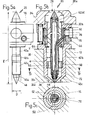
- Support ring 50 which has at least two, preferably three or more radial webs 52, either cause metered heat dissipation at selected points along the nozzle 20 or practically prevent heat dissipation by extensive insulation.
- the nozzle tip 48 is centered towards the sprue hole and the force originating from the flowing plastic melt is received on the support ring 50 on a shoulder or a collar 58.
- a larger diameter on the torpedo 20 prevents unintentional slipping in the filled hot runner.
- the electrically conductive heating tubes 30, 40 are preferably made of resistance material based on nickel alloys.
- the pin 38 and the nozzle tip 48 are made of highly thermally conductive materials, the nozzle tip 48 being designed to be particularly wear-resistant for processing glass-fiber-reinforced thermoplastics.
- the support ring 50 and other supports are preferably made of a ceramic material with low thermal conductivity, for example zirconium oxide.
- the support ring 50 can be designed such that webs 52 made of conductive material with insulating intermediate layers 54 or 56 are either radially on the outside (FIGS. 3a to 3c) or on the inside (FIG. 3d) are provided.
- Such non-conductive intermediate layers can be made of enamel or ceramic adhesive, a high-temperature adhesive or the like. consist.
- the respective different contact surface of the radial webs 52 can and should, however, permit axial movement in order to enable expansion compensation.
- the support ring 50 is preferably at a distance of two to five times the torpedo diameter D from the nozzle tip 48. This support results in metered heat dissipation to the outside, so that an increase in temperature in the region (in the direction of flow) in front of the support ring 50 is avoided in spite of the increased heating power in the nozzle tip 48.
- the heating power can easily be varied in a ratio of 1: 1.1 to 1: 5 over the length (1, FIG. 5a) of the nozzle 20.
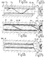
- An insulating compound M is present between the outer heating tube 40 and the inner heating tube 30 (see, for example, FIG. 2); it is also possible and provided according to the invention to use a plurality of insulating compositions M 1 , M 2 etc. (cf. FIGS. 14a, 15a, 15b) with different material properties and / or molded insulating parts.
- a thermal sensor 72 and, for example, sealed via a labyrinth 116 can be inserted into the insulation space in order to be able to determine the temperature at the nozzle tip 48.
- the thermal sensor 72 can be designed and arranged such that the temperature profile along the nozzle 20 can also be detected. In production operation, the thermal sensor 72 remains in the position shown with its measuring tip.
- the thermally conductive pin 38 e.g. consists of copper, ensures temperature compensation in the measuring point area at the nozzle tip 48.
- FIG. 2 shows a section of a nozzle 20, which largely corresponds to the structure according to FIG. 1a.
- the individual sections 30a, 30b, 30c of the inner heating tube 30 and the sections 40a, 40b (40c) of the outer heating tube 40 are not made in one piece, but are made of different parts which are electrically conductively connected to one another by a connection V, for example brazing are.
- the distributor 12 and its heating conductor 22 can also be applied to the distributor 12 and its heating conductor 22 in accordance with the exemplary embodiment in FIG. 4.
- the portion of the heat conductor 22 which is directly adjacent to the torpedo 20 can have a higher electrical resistance.
- the distributor 14 can have a cavity 24 of larger diameter than the bores adjoining on the left and right laterally.
- the ratio of the electrical resistances at the partial regions of the heating conductor 22 can be, for example, approximately 1: 1.25: (0.1 ... 0.2) and the diameter ratio of the bore 24 to the subsequent, narrower cavities approximately (1.1 ... 1.4): 1.
- a uniform temperature distribution over the length i of the torpedo 20 is achieved by the measures mentioned.
- This in turn has an outer heating tube 40 and an inner heating element arranged at a radial distance from it, which is designed here as a heating rod 30.
- At least one insulating compound M electrically separates heating rod 30 and outer heating tube 40; only at the top and bottom tips (48) is there a conductive connection.
- the heating rod In the lower part of section 30b, the heating rod has a lateral recess or groove for the electrically insulated embedding of the thermal sensor 72.
- the torpedo 20 can expand axially on both sides, so that practically no thermal expansion stresses occur as a result of temperature differences.
- the support 50 according to the invention can absorb twice the axial force, which contributes significantly to operational safety.
- the nozzle 20 is designed as a double heating tube.
- rings or sleeves 60 are attached electrically insulated from the heating pipes 30, 40.
- the double Heating tube significant advantages are achieved, because the resulting stress from the thermal expansion is almost non-existent and the flowing electrical current heats the plastic inside the heating tube 30 both on the way there and on the way back.
- the double heating tube with a heat-insulating mass M or various such masses to compensate and absorb the pressure forces inside the nozzle up to 2 kbar.
- the heating rod 22 or the inner heating tube 30 and the outer heating tube 40 are separated from one another by an insulating gap 88 (FIGS. 1a, 2), the width s of which is approximately one tenth of the respective outer heating tube diameter D.
- the temperature difference from the inner to the outer heating element therefore remains below 10 degrees.
- heat-conducting supports 62, 64 in the form of support ribs are attached. In addition to the power line and axial force transmission, they also serve to dissipate heat from the inner nozzle area. As already described, according to the invention the heating power is concentrated there in order to increase the temperature in the area of the material inlet 28 and directly at the nozzle tip 48. However, this could cause the temperature in the central region 26 to rise due to heat conduction within the heating elements.
- the radial support causes the necessary heat dissipation and additionally enables the nozzle tip 48 to be centered on the sprue hole of the tool 12.
- the heating line is in each case in a partial area of the tip 48 and the material inlet 28 as a short double heater tube trained. In this way, the desired high heating output is obtained at the ends of the nozzle 20, while the heat dissipation by the support elements 60 or 62, 64 takes place in a range which is not dangerous with regard to the heat concentration and temperature control.
- the middle sections 40b, 40c of the outer heating tube 40 can expediently consist of electrically highly conductive material.
- the support elements 62 and 64 are formed at least once on a nozzle 20 so that a seal from the outer heating tube 40 to the housing is achieved.
- the liquid plastic can enter the capillaries on the outside of the heating tube under pressure equalization; an undesired flow process on the outside of the heating tube 40 therefore does not take place. This avoids the conventionally possible flow past the outer diameter of the heating tube, which could result in the insulating material being washed out and could render the nozzle unusable.
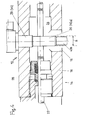
- An embodiment according to FIG. 9 provides a labyrinth 90 on the power supply line to the nozzle 20.
- the labyrinth 90 is e.g. coated with an insulating, high temperature resistant adhesive and poured out, so that a secure seal is guaranteed even at high pressures.
- it is essential for this to be deflected at least once, preferably several times, for example at an angle of 45 °, 60 ° and / or 90 °.
- FIGS. 5b, 6 and 7a show further possible solutions. It can be seen from FIGS. 7 b and 10 that the principle of redirecting the flow direction at least once is also applied to the thermocouple 72. In the embodiment according to FIG. 14 a, sealing takes place through the labyrinth 16.
- the axial force on the inner heating tube 30 is absorbed via a closed screen 74.
- the heating here is not direct, but with additional, heating coils 76 placed around the pipe 30.
- the power is adjusted in a manner known per se through the density of the windings 76.
- the heated pipe can also expand in relation to the housing 80 here.
- the increased power at the material inlet 28 and at the nozzle tip 48 is dissipated through the outer tube sections 40a, 40b and the supports 62, 64, so that no excess temperatures occur in the central region of the inner heating tube 30.
- a temperature adjustment is achieved over the length of the heating conductor 22 designed as a tube by changing the line cross section A, by changing the diameter of the cavity 24 on the distributor 14, by selecting the outside diameter of the heating tube 22 and of the subsequent connecting piece 92 and / or by material selection, in particular in that the connecting piece 92 is designed with a higher specific resistance than the heating conductor 22 and its current supply 94. While the latter, for example, has a specific resistance of 0.1 ... 0.2 Ohm ⁇ mm 2 / m, the connector 92 may have a resistivity of 1.3 ohmmm2 / m.
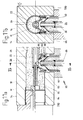
- a frusto-conical screen 80 is fixedly or displaceably attached to the tube 22 (FIGS. 11a, 11b).
- An insulated ring 82 is used for this purpose, which can consist of two parts with an insulating intermediate layer 84.
- the largest diameter of the screen 80 is smaller than that of the narrower cavity 24 in the distributor 14, so that the heating tube 22 together with the truncated cone 80 can be inserted into the transverse distributor bore 16, 24.
- the space 96 delimited from this is filled with plastic when it is started up for the first time. This solidifies and seals the connector.
- FIGS. 12a and 12b permit a further type of heating of the inner tube 22/30 with almost complete thermal separation of the hot inner part from the distributor housing 18.
- the heating tube 22/30 is embedded in insulating compound M. Due to the very small power supply 78, very little heat is dissipated, while the connection is elastic. A sleeve 86 on the heating pipes permits thermal expansion, for example when branching off. an elbow or the like
- the heat concentration at the ends of the nozzle or torpedo 20 it is important that the heat transfer there is reduced relative to the central part 26, e.g. due to increased distances, low thermal conductivity values or the like.
- the area of the nozzle tip 48 is to be specially designed, it may be expedient to arrange the lower support 64 perpendicular to the axis between the sections 40c, 40d of the outer heating tube 40, for example according to FIG. 7a.
- a shoulder at the lower nozzle end is created with obliquely extending supports 64, which contributes to the desired heat concentration.
- nozzle end is in the form of a distributor head, which is e.g. can have two or more tube webs 48, 48 'and / or a bottom or screen 100 which has circumferential openings - such as slots, round holes or the like. - limited.
- the injection molding material is passed into one or more mold cavities (not shown) via each such nozzle tip.
- 14b can be designed as axial grooves 106 and / or as holes or bores 108. Inclined and radial courses are also possible.
- the inner heating conductor 22 or the inner heating tube 30 can be a helical tube and can be provided with an outer protective tube 110, an inner protective tube 112 and / or an insulating coating 114 or insulating rings.
Landscapes
- Engineering & Computer Science (AREA)
- Manufacturing & Machinery (AREA)
- Mechanical Engineering (AREA)
- Moulds For Moulding Plastics Or The Like (AREA)
- Injection Moulding Of Plastics Or The Like (AREA)
- Dental Preparations (AREA)
Priority Applications (1)
| Application Number | Priority Date | Filing Date | Title |
|---|---|---|---|
| AT84103278T ATE38636T1 (de) | 1983-10-18 | 1984-03-24 | Spritzgiessvorrichtung. |
Applications Claiming Priority (2)
| Application Number | Priority Date | Filing Date | Title |
|---|---|---|---|
| DE3337803 | 1983-10-18 | ||
| DE3337803A DE3337803C2 (de) | 1983-10-18 | 1983-10-18 | Heißkanalsystem für Spritzgießvorrichtungen |
Publications (3)
| Publication Number | Publication Date |
|---|---|
| EP0137888A2 true EP0137888A2 (fr) | 1985-04-24 |
| EP0137888A3 EP0137888A3 (en) | 1986-07-02 |
| EP0137888B1 EP0137888B1 (fr) | 1988-11-17 |
Family
ID=6212107
Family Applications (1)
| Application Number | Title | Priority Date | Filing Date |
|---|---|---|---|
| EP84103278A Expired EP0137888B1 (fr) | 1983-10-18 | 1984-03-24 | Dispositif de moulage par injection |
Country Status (3)
| Country | Link |
|---|---|
| EP (1) | EP0137888B1 (fr) |
| AT (1) | ATE38636T1 (fr) |
| DE (2) | DE3337803C2 (fr) |
Cited By (12)
| Publication number | Priority date | Publication date | Assignee | Title |
|---|---|---|---|---|
| EP0229689A3 (en) * | 1986-01-08 | 1988-12-21 | Fast Heat Element | Plastic injection moulding system with multiple tip torpedo heater |
| US4902219A (en) * | 1986-01-08 | 1990-02-20 | Fast Heat Element Manufacturing Company, Inc. | Plastic injection molding system with multiple tip torpedo heater |
| EP0402502A1 (fr) * | 1989-06-12 | 1990-12-19 | Jobst Ulrich Gellert | Système de moulage par injection ayant une bride de positionnement thermique |
| EP0443203A3 (en) * | 1990-02-21 | 1992-03-11 | Sfr Formenbau Dangelmaier Gmbh | Heated nozzle, so-called long nozzle for a plastic injection moulding mould |
| EP0854027A1 (fr) * | 1997-01-21 | 1998-07-22 | Husky Injection Molding Systems Ltd. | Ensemble modulaire de buse d'injection isolé |
| EP0927621A3 (fr) * | 1997-12-31 | 2000-05-17 | EWIKON Heisskanalsysteme GmbH & Co. KG | Système à canal chaud, en particulier pour une machine à mouler par injection ou moule d'injection de matières plastiques |
| CN101337422B (zh) * | 2007-07-06 | 2013-08-14 | 热诺有限公司 | 用于注射模的绝热隔离件 |
| US10779609B2 (en) | 2017-04-24 | 2020-09-22 | Nike, Inc. | Apparel and sporting equipment with an UV radiation curable material and method of manufacturing thereof |
| US11122847B2 (en) | 2017-04-24 | 2021-09-21 | Nike, Inc. | Article with UV radiation curable material adhered to textile and method of making the same |
| US11136475B2 (en) | 2017-04-24 | 2021-10-05 | Nike, Inc. | Articles and components with UV radiation curable elastomeric materials and methods of making the same |
| US11673294B2 (en) | 2017-04-24 | 2023-06-13 | Nike, Inc. | Transparent tooling for UV radiation curable rubber |
| US12004593B2 (en) | 2016-06-16 | 2024-06-11 | Adidas Ag | UV curable lattice microstructure for footwear |
Families Citing this family (1)
| Publication number | Priority date | Publication date | Assignee | Title |
|---|---|---|---|---|
| DE3718187C2 (de) * | 1987-05-29 | 1996-09-05 | Ewikon Entwicklung Konstr | Mehrfachangußdüse |
Family Cites Families (8)
| Publication number | Priority date | Publication date | Assignee | Title |
|---|---|---|---|---|
| US3091812A (en) * | 1958-09-05 | 1963-06-04 | Henry J Witkowski | Hot runner mold |
| US3520026A (en) * | 1968-02-12 | 1970-07-14 | Phillips Petroleum Co | Runner system having resistance heated components |
| CA1097472A (fr) * | 1976-07-16 | 1981-03-17 | Walter R. Crandell | Buse chauffee a l'electricite et methode de production |
| DE2824971C2 (de) * | 1978-06-07 | 1982-10-28 | EWIKON Entwicklung und Konstruktion GmbH & Co KG, 4900 Herford | Düse für eine Kunststoffspritzgießmaschine oder Kunststoffspritzgießform mit beheizbarer Angußdüse |
| NL7900927A (nl) * | 1979-02-06 | 1980-08-08 | Anthonie Van Den Brink | Verwarmingspatroon. |
| DE2938832A1 (de) * | 1979-09-26 | 1981-04-09 | EWIKON Entwicklung und Konstruktion GmbH & Co KG, 4900 Herford | Vorrichtung mit einem heisskanalsystem zum zufuehren einer kunststoffschmelze zu einer spritzgussform |
| CA1149569A (fr) * | 1981-03-20 | 1983-07-12 | Jobst U. Gellert | Systeme de moulage a injection laterale |
| DE3301272A1 (de) * | 1983-01-17 | 1984-07-19 | Walter Fr. 3004 Isernhagen Davidsmeyer | Vorrichtung zum zufuehren von thermoplasten zu einem formwerkzeug |
-
1983
- 1983-10-18 DE DE3337803A patent/DE3337803C2/de not_active Expired
-
1984
- 1984-03-24 EP EP84103278A patent/EP0137888B1/fr not_active Expired
- 1984-03-24 AT AT84103278T patent/ATE38636T1/de not_active IP Right Cessation
- 1984-03-24 DE DE8484103278T patent/DE3475175D1/de not_active Expired
Cited By (16)
| Publication number | Priority date | Publication date | Assignee | Title |
|---|---|---|---|---|
| EP0229689A3 (en) * | 1986-01-08 | 1988-12-21 | Fast Heat Element | Plastic injection moulding system with multiple tip torpedo heater |
| US4902219A (en) * | 1986-01-08 | 1990-02-20 | Fast Heat Element Manufacturing Company, Inc. | Plastic injection molding system with multiple tip torpedo heater |
| EP0402502A1 (fr) * | 1989-06-12 | 1990-12-19 | Jobst Ulrich Gellert | Système de moulage par injection ayant une bride de positionnement thermique |
| EP0443203A3 (en) * | 1990-02-21 | 1992-03-11 | Sfr Formenbau Dangelmaier Gmbh | Heated nozzle, so-called long nozzle for a plastic injection moulding mould |
| EP0854027A1 (fr) * | 1997-01-21 | 1998-07-22 | Husky Injection Molding Systems Ltd. | Ensemble modulaire de buse d'injection isolé |
| DE19758322B4 (de) * | 1997-12-31 | 2008-09-18 | EWIKON Heißkanalsysteme GmbH & Co. KG | Elektrisch betriebenes Heizelement |
| US6146126A (en) * | 1997-12-31 | 2000-11-14 | Ewikon Heisskanalsysteme Gmbh & Kommanditgesellschaft | Hot runner system, in particular hot runner nozzle for an injection molding machine or plastics injection mold |
| DE19758323B4 (de) * | 1997-12-31 | 2006-05-04 | EWIKON Heißkanalsysteme GmbH & Co KG | Heißkanalabschnitt, insbesondere Heißkanaldüse für eine Spritzgießmaschine oder Kunststoffspritzgießform |
| EP0927621A3 (fr) * | 1997-12-31 | 2000-05-17 | EWIKON Heisskanalsysteme GmbH & Co. KG | Système à canal chaud, en particulier pour une machine à mouler par injection ou moule d'injection de matières plastiques |
| CN101337422B (zh) * | 2007-07-06 | 2013-08-14 | 热诺有限公司 | 用于注射模的绝热隔离件 |
| US12004593B2 (en) | 2016-06-16 | 2024-06-11 | Adidas Ag | UV curable lattice microstructure for footwear |
| US10779609B2 (en) | 2017-04-24 | 2020-09-22 | Nike, Inc. | Apparel and sporting equipment with an UV radiation curable material and method of manufacturing thereof |
| US11122847B2 (en) | 2017-04-24 | 2021-09-21 | Nike, Inc. | Article with UV radiation curable material adhered to textile and method of making the same |
| US11136475B2 (en) | 2017-04-24 | 2021-10-05 | Nike, Inc. | Articles and components with UV radiation curable elastomeric materials and methods of making the same |
| US11673294B2 (en) | 2017-04-24 | 2023-06-13 | Nike, Inc. | Transparent tooling for UV radiation curable rubber |
| US12030225B2 (en) | 2017-04-24 | 2024-07-09 | Nike, Inc. | Transparent tooling for UV radiation curable rubber |
Also Published As
| Publication number | Publication date |
|---|---|
| DE3475175D1 (en) | 1988-12-22 |
| EP0137888B1 (fr) | 1988-11-17 |
| DE3337803A1 (de) | 1985-05-02 |
| ATE38636T1 (de) | 1988-12-15 |
| DE3337803C2 (de) | 1986-07-10 |
| EP0137888A3 (en) | 1986-07-02 |
Similar Documents
| Publication | Publication Date | Title |
|---|---|---|
| DE3523826C2 (de) | Geheizte Spritzgußdüse mit eingelötetem Heizelement und Verfahren zu deren Herstellung | |
| DE3140164C2 (de) | Angußbuchse und Verfahren zu ihrer Herstellung | |
| EP0137888B1 (fr) | Dispositif de moulage par injection | |
| CH656573A5 (de) | Verfahren zur herstellung einer heizsonde fuer spritzgussmaschinen sowie eine nach dem verfahren hergestellte heizsonde. | |
| DE3835086A1 (de) | Spritzgiessduese | |
| DE4003971C2 (de) | Spritzgießdüse | |
| DE3301272C2 (fr) | ||
| EP0014712A1 (fr) | Manchon a souder en matiere thermoplastique. | |
| EP0528315B1 (fr) | Buse à canal chaud | |
| DE69708935T2 (de) | Heisskanaldüse | |
| DE3531127C2 (de) | Heizelement für Formwerkzeuge von Spritzgießmaschinen | |
| DE2539785C3 (de) | Heißkanalspritzdüse | |
| DE4005437C2 (fr) | ||
| EP0528316B1 (fr) | Dispositif de moulage par injection avec buse à canal chaud | |
| DE4300971B4 (de) | Spritzgießdüse und Verfahren zur Herstellung eines Düsenkörpers einer Spritzdüse | |
| DE69214261T2 (de) | Verfahren zur Herstellung eines Spritzgiesstorpedos | |
| DE20211328U1 (de) | Temperaturfühler und Heizvorrichtung für Heißkanalsysteme | |
| DE60125577T2 (de) | Metallüberzug für einen anschluss eines dickschicht-heizelementes | |
| DE3335277C2 (fr) | ||
| AT286607B (de) | Mehrfachspritzgußform für thermoplastische Kunststoffe mit wenigstens einer Punktanspritzung | |
| EP0194460B1 (fr) | Appareil de moulage par injection | |
| DE19522716C1 (de) | Vorrichtung zur Beheizung von Verteilerrohren zum Zuführen von Fluiden | |
| DE7415211U (de) | Vorrichtung zur Strombegrenzung | |
| EP3609292B1 (fr) | Dispositif de chauffage de liquides | |
| DE8110364U1 (de) | "heisskanalspritzduese" |
Legal Events
| Date | Code | Title | Description |
|---|---|---|---|
| PUAI | Public reference made under article 153(3) epc to a published international application that has entered the european phase |
Free format text: ORIGINAL CODE: 0009012 |
|
| AK | Designated contracting states |
Designated state(s): AT BE CH DE FR GB IT LI LU NL SE |
|
| RTI1 | Title (correction) | ||
| PUAL | Search report despatched |
Free format text: ORIGINAL CODE: 0009013 |
|
| AK | Designated contracting states |
Kind code of ref document: A3 Designated state(s): AT BE CH DE FR GB IT LI LU NL SE |
|
| 17P | Request for examination filed |
Effective date: 19861218 |
|
| 17Q | First examination report despatched |
Effective date: 19871127 |
|
| GRAA | (expected) grant |
Free format text: ORIGINAL CODE: 0009210 |
|
| AK | Designated contracting states |
Kind code of ref document: B1 Designated state(s): AT BE CH DE FR GB IT LI LU NL SE |
|
| PG25 | Lapsed in a contracting state [announced via postgrant information from national office to epo] |
Ref country code: SE Effective date: 19881117 |
|
| REF | Corresponds to: |
Ref document number: 38636 Country of ref document: AT Date of ref document: 19881215 Kind code of ref document: T |
|
| ITF | It: translation for a ep patent filed | ||
| GBT | Gb: translation of ep patent filed (gb section 77(6)(a)/1977) | ||
| REF | Corresponds to: |
Ref document number: 3475175 Country of ref document: DE Date of ref document: 19881222 |
|
| ET | Fr: translation filed | ||
| PLBI | Opposition filed |
Free format text: ORIGINAL CODE: 0009260 |
|
| 26 | Opposition filed |
Opponent name: EWIKON ENTWICKLUNG UND KONSTRUKTION GMBH & CO. KOM Effective date: 19890816 |
|
| NLR1 | Nl: opposition has been filed with the epo |
Opponent name: EWIKON ENTWICKLUNG UND KONSTRUKTION GMBH & CO. |
|
| ITTA | It: last paid annual fee | ||
| 29A | Proceedings stayed after grant |
Effective date: 19910320 |
|
| 29F | Proceedings resumed after grant [after stay of proceedings according to rule 14 epc] |
Effective date: 19940525 |
|
| EPTA | Lu: last paid annual fee | ||
| RAP2 | Party data changed (patent owner data changed or rights of a patent transferred) |
Owner name: DIPL.-ING. HERBERT GUENTHER GESELLSCHAFT MBH |
|
| NLT2 | Nl: modifications (of names), taken from the european patent patent bulletin |
Owner name: DIPL.-ING. HERBERT GUENTHER GESELLSCHAFT MBH TE PE |
|
| PLBM | Termination of opposition procedure: date of legal effect published |
Free format text: ORIGINAL CODE: 0009276 |
|
| STAA | Information on the status of an ep patent application or granted ep patent |
Free format text: STATUS: OPPOSITION PROCEDURE CLOSED |
|
| 27C | Opposition proceedings terminated |
Effective date: 19940911 |
|
| PGFP | Annual fee paid to national office [announced via postgrant information from national office to epo] |
Ref country code: FR Payment date: 19990209 Year of fee payment: 16 |
|
| PGFP | Annual fee paid to national office [announced via postgrant information from national office to epo] |
Ref country code: GB Payment date: 19990211 Year of fee payment: 16 Ref country code: CH Payment date: 19990211 Year of fee payment: 16 |
|
| PGFP | Annual fee paid to national office [announced via postgrant information from national office to epo] |
Ref country code: AT Payment date: 19990215 Year of fee payment: 16 |
|
| PGFP | Annual fee paid to national office [announced via postgrant information from national office to epo] |
Ref country code: LU Payment date: 19990216 Year of fee payment: 16 Ref country code: BE Payment date: 19990216 Year of fee payment: 16 |
|
| PGFP | Annual fee paid to national office [announced via postgrant information from national office to epo] |
Ref country code: NL Payment date: 19990330 Year of fee payment: 16 |
|
| PGFP | Annual fee paid to national office [announced via postgrant information from national office to epo] |
Ref country code: DE Payment date: 19990506 Year of fee payment: 16 |
|
| PG25 | Lapsed in a contracting state [announced via postgrant information from national office to epo] |
Ref country code: LU Free format text: LAPSE BECAUSE OF NON-PAYMENT OF DUE FEES Effective date: 20000324 Ref country code: GB Free format text: LAPSE BECAUSE OF NON-PAYMENT OF DUE FEES Effective date: 20000324 Ref country code: AT Free format text: LAPSE BECAUSE OF NON-PAYMENT OF DUE FEES Effective date: 20000324 |
|
| PG25 | Lapsed in a contracting state [announced via postgrant information from national office to epo] |
Ref country code: LI Free format text: LAPSE BECAUSE OF NON-PAYMENT OF DUE FEES Effective date: 20000331 Ref country code: CH Free format text: LAPSE BECAUSE OF NON-PAYMENT OF DUE FEES Effective date: 20000331 Ref country code: BE Free format text: LAPSE BECAUSE OF NON-PAYMENT OF DUE FEES Effective date: 20000331 |
|
| BERE | Be: lapsed |
Owner name: GUNTNER HERBERT Effective date: 20000331 |
|
| PG25 | Lapsed in a contracting state [announced via postgrant information from national office to epo] |
Ref country code: NL Free format text: LAPSE BECAUSE OF NON-PAYMENT OF DUE FEES Effective date: 20001001 |
|
| GBPC | Gb: european patent ceased through non-payment of renewal fee |
Effective date: 20000324 |
|
| REG | Reference to a national code |
Ref country code: CH Ref legal event code: PL |
|
| PG25 | Lapsed in a contracting state [announced via postgrant information from national office to epo] |
Ref country code: FR Free format text: LAPSE BECAUSE OF NON-PAYMENT OF DUE FEES Effective date: 20001130 |
|
| NLV4 | Nl: lapsed or anulled due to non-payment of the annual fee |
Effective date: 20001001 |
|
| REG | Reference to a national code |
Ref country code: FR Ref legal event code: ST |
|
| PG25 | Lapsed in a contracting state [announced via postgrant information from national office to epo] |
Ref country code: DE Free format text: LAPSE BECAUSE OF NON-PAYMENT OF DUE FEES Effective date: 20010103 |