EP0137895A2 - Klärung von Flüssigkeiten - Google Patents
Klärung von Flüssigkeiten Download PDFInfo
- Publication number
- EP0137895A2 EP0137895A2 EP84104316A EP84104316A EP0137895A2 EP 0137895 A2 EP0137895 A2 EP 0137895A2 EP 84104316 A EP84104316 A EP 84104316A EP 84104316 A EP84104316 A EP 84104316A EP 0137895 A2 EP0137895 A2 EP 0137895A2
- Authority
- EP
- European Patent Office
- Prior art keywords
- quiescent zone
- flow path
- fluid
- triangle
- zone
- Prior art date
- Legal status (The legal status is an assumption and is not a legal conclusion. Google has not performed a legal analysis and makes no representation as to the accuracy of the status listed.)
- Withdrawn
Links
Images


Classifications
-
- C—CHEMISTRY; METALLURGY
- C02—TREATMENT OF WATER, WASTE WATER, SEWAGE, OR SLUDGE
- C02F—TREATMENT OF WATER, WASTE WATER, SEWAGE, OR SLUDGE
- C02F3/00—Biological treatment of water, waste water, or sewage
- C02F3/02—Aerobic processes
- C02F3/12—Activated sludge processes
- C02F3/1236—Particular type of activated sludge installations
- C02F3/1257—Oxidation ditches
-
- B—PERFORMING OPERATIONS; TRANSPORTING
- B01—PHYSICAL OR CHEMICAL PROCESSES OR APPARATUS IN GENERAL
- B01D—SEPARATION
- B01D21/00—Separation of suspended solid particles from liquids by sedimentation
-
- B—PERFORMING OPERATIONS; TRANSPORTING
- B01—PHYSICAL OR CHEMICAL PROCESSES OR APPARATUS IN GENERAL
- B01D—SEPARATION
- B01D21/00—Separation of suspended solid particles from liquids by sedimentation
- B01D21/0039—Settling tanks provided with contact surfaces, e.g. baffles, particles
-
- B—PERFORMING OPERATIONS; TRANSPORTING
- B01—PHYSICAL OR CHEMICAL PROCESSES OR APPARATUS IN GENERAL
- B01D—SEPARATION
- B01D21/00—Separation of suspended solid particles from liquids by sedimentation
- B01D21/0039—Settling tanks provided with contact surfaces, e.g. baffles, particles
- B01D21/0042—Baffles or guide plates
-
- B—PERFORMING OPERATIONS; TRANSPORTING
- B01—PHYSICAL OR CHEMICAL PROCESSES OR APPARATUS IN GENERAL
- B01D—SEPARATION
- B01D21/00—Separation of suspended solid particles from liquids by sedimentation
- B01D21/02—Settling tanks with single outlets for the separated liquid
-
- B—PERFORMING OPERATIONS; TRANSPORTING
- B01—PHYSICAL OR CHEMICAL PROCESSES OR APPARATUS IN GENERAL
- B01D—SEPARATION
- B01D21/00—Separation of suspended solid particles from liquids by sedimentation
- B01D21/24—Feed or discharge mechanisms for settling tanks
- B01D21/2488—Feed or discharge mechanisms for settling tanks bringing about a partial recirculation of the liquid, e.g. for introducing chemical aids
-
- C—CHEMISTRY; METALLURGY
- C02—TREATMENT OF WATER, WASTE WATER, SEWAGE, OR SLUDGE
- C02F—TREATMENT OF WATER, WASTE WATER, SEWAGE, OR SLUDGE
- C02F1/00—Treatment of water, waste water, or sewage
- C02F1/52—Treatment of water, waste water, or sewage by flocculation or precipitation of suspended impurities
-
- B—PERFORMING OPERATIONS; TRANSPORTING
- B01—PHYSICAL OR CHEMICAL PROCESSES OR APPARATUS IN GENERAL
- B01D—SEPARATION
- B01D2221/00—Applications of separation devices
- B01D2221/02—Small separation devices for domestic application, e.g. for canteens, industrial kitchen, washing machines
-
- Y—GENERAL TAGGING OF NEW TECHNOLOGICAL DEVELOPMENTS; GENERAL TAGGING OF CROSS-SECTIONAL TECHNOLOGIES SPANNING OVER SEVERAL SECTIONS OF THE IPC; TECHNICAL SUBJECTS COVERED BY FORMER USPC CROSS-REFERENCE ART COLLECTIONS [XRACs] AND DIGESTS
- Y02—TECHNOLOGIES OR APPLICATIONS FOR MITIGATION OR ADAPTATION AGAINST CLIMATE CHANGE
- Y02W—CLIMATE CHANGE MITIGATION TECHNOLOGIES RELATED TO WASTEWATER TREATMENT OR WASTE MANAGEMENT
- Y02W10/00—Technologies for wastewater treatment
- Y02W10/10—Biological treatment of water, waste water, or sewage
Definitions
- This invention relates to the clarification of fluids containing suspended settleable solids.
- waste water other than sewage include drainage water containing clay or silt, clean-up and process water from food processing industries, water containing precipitated particles of heavy metals from the electroplating industry, pickle liquor from steel plant operations, waste water from the metal finishing industry, waste water from painting operations, etc. It is desirable to remove the suspended solids prior to returning the waste water to the environment. Water supplies frequently contain silt, clay, and objectionable dissolved solids which can be chemically treated to precipitate the unwanted materials. It is necessary in most instances to remove these suspensions of silt and precipitates in order to obtain water suitable for domestic and other uses. Additionally, certain liquid products containing suspended solids must be clarified to enhance their value.
- this is accomplished by passing the fluid to a clarifier where the suspended solids are permitted to settle, forming a sludge which is disposed of by suitable means.
- Clarified effluent is withdrawn from the top of the clarifier for use or return to the environment.
- Settled waste solids are suitably disposed of, e.g., in land fill.
- Clarified effluent is removed from the quiescent zone in the upper portion of the clarifier through orifice pipes submerged about one foot beneath the water's surface.
- the aeration basin in which the clarifier is used is an oxidation ditch which includes a closed flow path, i.e., one or more pumps are provided for circulating the liquid through the flow path beneath the clarifier.
- the liquid enters beneath the clarifier at a higher pressure than the liquid exiting beneath the clarifier and at the other end of the flow path because of head loss experienced during the flow of the liquid under the clarifier.
- an apparatus for clarifying fluids in a fluid container e.g., a tank, basin or lagoon.
- the apparatus comprises a first means for defining a quiescent zone in the container.
- the first means includes a pair of end walls, a pair of side walls, and a bottom wall comprising at least one surface having open and closed areas to permit settled solids to pass out of the quiescent zone.
- Means are provided to introduce fluid containing suspended solids into the quiescent zone.
- the bottom wall also permits fluid containing suspended solids to pass into the quiescent zone.
- the bottom wall may comprise spaced, sloping surfaces extending across the bottom.
- a second means is located below the first means and defines a fluid flow path below and in communication with the bottom wall of the quiescent zone.
- the second means has both an inlet and an outlet.
- a pump means is provided which is located substantially adjacent to the outlet of the second means and which creates a low pressure area at this outlet. This low pressure area causes the fluid to flow into the inlet of the second means, along the flow path.
- a portion of the fluid passes into the quiescent zone through the open areas in the bottom wall and a portion of the fluid passes out the outlet.
- Settled solids pass through the open areas in the bottom wall from the quiescent zone into the flow path.
- a third means is provided in the first means for removing clarified fluid from the top of the first means and from the fluid container.
- the second means which defines the fluid flow path is bounded on the top by the bottom wall of the first means, closed on the bottom and sides thereof and open at each end.
- the pump means is situated in the opening at the outlet end of the second means.
- the pump means is situated above the opening in the outlet end of the second means adjacent the end wall of the first means.
- the bottom wall of the first means comprises a plurality of spaced, horizontal members extending substantially perpendicular to the flow path, the cross section of each member comprising a triangle, with the apex of the triangle facing the quiescent zone so as to provide no horizontal surfaces on the bottom facing the quiescent zone.
- the use of the clarifier apparatus of this invention results in improved hydraulics over the system described by Christopher et al, supra, i.e., the solid particles entering the quiescent zone will not rise as high in the quiescent zone resulting in a more efficient formation of a clarified supernatant.
- the improved hydraulics are inherent in the fact that the volume of fluid which is taken through the flow path is independent of the volume of the fluid container. Further, the solid particles tend to be pulled into the flow path by a venturi effect which tends to prevent blockage of the open areas in the bottom wall of the quiescent zone. Placing the pump means at the exit of the flow path results in an enhanced venturi effect over that which would be obtained by placing the pump means at the entrance to the flow path.
- the clarifier apparatus of this invention can be utilized in a static or non-flowing, non-circulating fluid treatment system. This permits installation in circular or other economically configured systems.
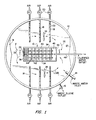
- a waste water clarifier system 10 is located in a waste water tank 12 which may be a tank, basin or lagoon.
- the waste water container 12 is circular in shape although it may be other shapes, e.g., it may be oval in shape.
- the clarifier system 10 is shown located in the center of the container 12, it may be located in other positions, e.g., close to one side of the container. Sewage, which may have first been treated in a primary settling tank to remove waste primary sludge is passed to the container 12 through waste water inlet 14.
- means in the form of an outlet conduit 16 is provided for removing waste sludge from the container by wasting a stream of mixed liquor.
- Air diffuser pipes 18 are provided for aerating the mixed liquor in the container 12 to reduce the BOD content thereof. Air is supplied by means of pumps 20 and is blown through the diffusers 22 in the pipes 18 into the mixed liquor. It will be understood that aeration is not necessary in the treatment of fluid systems which do not contain bio-degradable materials.
- circulation pumps 24 may be provided to move the mixed liquor in the directions indicated by the directional arrows 26.
- the circulation pumps 24 are not necessary and sometimes it is desirable to eliminate them from the system. It is preferred that the flow imparted by circulation pumps 24 to the mixed liquor be such that the flow from one pump negates the flow from the other pump prior to entry into the waste water clarifier system 10. In other words, it is preferred that there be zero velocity of the mixed liquor as it enters the flow path.
- Deflector 27 may be provided to help accomplish this result.
- a pump 28 is located at the downstream end of the clarifier system 10.
- the pump 28 includes an impeller pump blade 29 and a motor 30.
- the pump 28 creates a low pressure area at the outlet of the clarifier system 10 causing waste water to flow into the flow path entrance 66.
- a deflector 31 splits the flow coming out of the clarifier system as indicated by directional arrows 32.
- the clarifier system 10 includes side walls 34, an inlet end wall 36, an outlet end wall 38 and baffle surfaces 40. Collection pipes 42 are provided to drain off the clarified supernatant. The clarified supernatant enters the pipes 42 through holes 44 and enters the clear water basin 46 from whence it is pumped out of the system through clarified water outlet 48.
- the clarifier system 10 comprises side wall 34, inlet end wall 36, outlet end wall 38 and bottom 50.
- a quiescent zone 52 is provided which is bounded on one end by baffle wall 54, on the other end by clear water basin wall 56 and on the bottom by baffle surfaces 40.
- the quiescent zone 52 suspended solids settle from the waste water, thereby creating a stratum of clarified supernatant water which is shown in Fig. 2 above the boundary 57.
- the clarified supernatant is passed out of the system as previously described.
- the baffle surfaces 40 include a series of surfaces of sufficient slope to allow a terminating end 58 of one surface to be below the beginning end 60 of another surface. There is an open area 62 between the terminating end 58 and the beginning end 60. "This relationship forms the constricted opening necessary for hydraulics to be established.
- the baffle surfaces could be formed of flat plates, inverted V-shaped plates, L-shaped plates, triangular-shaped prisms, or hemispherical curved surfaces. In the embodiments shown in Figs. 2 and 7, the baffle surfaces are triangular in cross-section, with the apex of the triangle facing the quiescent zone so as to provide no horizontal surfaces facing the quiescent zone.
- a flow path is provided underneath the baffle surfaces 40 and under the bottom 64 of the clear water basin 46.
- the flow path is bounded on the bottom by the bottom 50 of the clarifier system and on the sides by side walls 34. It includes an entrance 66 which comprises an opening in inlet wall 36 and an exit 68 which comprises an opening between baffle wall 54 and the bottom 50 of the clarifier system.
- the pump 28 is preferably a low speed large impeller pump.
- the pump 28 is installed in an outlet opening 70 in outlet wall 38 between outlet wall 38 and baffle 54.
- the wall 38 acts as a cowl for the pump 28 to increase the draft.
- the pump forces water out of the outlet 70 creating a suction or a low pressure area above the perforated plate 72.
- This causes waste water to be drawn from the waste water container 12 through the entrance 66 to the flow path, along the flow path underneath the bottom 64 of the clear water basin and the baffle surfaces 40, out the exit 68 to the flow path, up through the perforated plate 72 and out the outlet 70.
- the presence of the perforated plate 72 generates a small head loss and insures equal distribution of underflow.
- a portion of the waste water underneath the baffle surfaces 40 passes into the quiescent zone through the open areas 62 and settled solids pass through the open areas 62 from the quiescent zone into the flow path.
- the minimum pump speed required is that resulting in a liquid velocity of the waste water in the flow path so as to prevent substantial settling of solids from the quiescent zone onto the baffle surfaces 40.
- Fig. 6 is similar to Fig. 1 except that only one circulation pump 100 is provided. This creates a circular movement of the waste water as indicated by directional arrows 102.
- the clarifier system 104 is provided with influent guides or straightening vanes 106 which are located at the entrance to the flow path under the baffle surfaces 40. The purpose of the vanes 106 is to straighten the flow of the waste water from the curved flow path as it enters the clarifier system.
- the clarifier system 104 is also provided with a baffle 108 which is located at the exit end of the flow path. The purpose of the baffle 108 is to direct the waste water flowing under the baffle surfaces 40 through the exit to the flow path into the direction of the basin flow.
- Fig. 7 is similar to Fig. 2 except that it shows pump 200 located adjacent the bottom of the clarifier system 202.
- the tank bottom wall 204 also serves as the bottom of the clarifier system. Waste water is drawn underneath the baffle surfaces 40 as indicated by directional arrows 206.
Landscapes
- Chemical & Material Sciences (AREA)
- Chemical Kinetics & Catalysis (AREA)
- Life Sciences & Earth Sciences (AREA)
- Water Supply & Treatment (AREA)
- Organic Chemistry (AREA)
- Hydrology & Water Resources (AREA)
- Engineering & Computer Science (AREA)
- Environmental & Geological Engineering (AREA)
- Microbiology (AREA)
- Biodiversity & Conservation Biology (AREA)
- Biological Treatment Of Waste Water (AREA)
- Separation Of Suspended Particles By Flocculating Agents (AREA)
- Physical Water Treatments (AREA)
- Detergent Compositions (AREA)
- Filtering Of Dispersed Particles In Gases (AREA)
- Physical Or Chemical Processes And Apparatus (AREA)
Applications Claiming Priority (2)
| Application Number | Priority Date | Filing Date | Title |
|---|---|---|---|
| US535558 | 1983-09-27 | ||
| US06/535,558 US4455239A (en) | 1983-09-27 | 1983-09-27 | Clarification of fluids |
Publications (2)
| Publication Number | Publication Date |
|---|---|
| EP0137895A2 true EP0137895A2 (de) | 1985-04-24 |
| EP0137895A3 EP0137895A3 (de) | 1987-05-13 |
Family
ID=24134744
Family Applications (1)
| Application Number | Title | Priority Date | Filing Date |
|---|---|---|---|
| EP84104316A Withdrawn EP0137895A3 (de) | 1983-09-27 | 1984-04-17 | Klärung von Flüssigkeiten |
Country Status (19)
| Country | Link |
|---|---|
| US (1) | US4455239A (de) |
| EP (1) | EP0137895A3 (de) |
| JP (1) | JPS6071010A (de) |
| KR (1) | KR910003081B1 (de) |
| AU (1) | AU562160B2 (de) |
| BR (1) | BR8402951A (de) |
| CA (1) | CA1234767A (de) |
| DK (1) | DK160811C (de) |
| ES (2) | ES8507008A1 (de) |
| FI (1) | FI843776A7 (de) |
| GR (1) | GR82146B (de) |
| IE (1) | IE57618B1 (de) |
| IN (1) | IN161451B (de) |
| MX (1) | MX160438A (de) |
| NO (1) | NO162378B (de) |
| NZ (1) | NZ208219A (de) |
| PH (2) | PH20737A (de) |
| PT (1) | PT78463B (de) |
| ZA (1) | ZA845243B (de) |
Families Citing this family (7)
| Publication number | Priority date | Publication date | Assignee | Title |
|---|---|---|---|---|
| US4596658A (en) * | 1984-01-30 | 1986-06-24 | Mandt Mikkel G | Sequencing batch reactor decanter systems |
| US4614589A (en) * | 1985-02-12 | 1986-09-30 | Smith & Loveless | Method and apparatus for biological aerobic wastewater treatment |
| US4772401A (en) * | 1986-08-21 | 1988-09-20 | Rawlins P J Thomas | Method of reducing contaminants in a fuel tank |
| US4952310A (en) * | 1987-03-03 | 1990-08-28 | Mcmahan Anthony A | Intrachannel clarifier |
| US4816157A (en) * | 1987-05-14 | 1989-03-28 | Jennelle Ernest M | Hydraulic sweep clarifier |
| US5874003A (en) * | 1997-06-25 | 1999-02-23 | Rose; Bryan L. | Wastewater treatment apparatus with floating clarifier |
| FI107813B (fi) * | 1999-06-17 | 2001-10-15 | Outokumpu Oy | Erotuselin altaan pohjaosan erottamiseksi muusta altaasta |
Family Cites Families (7)
| Publication number | Priority date | Publication date | Assignee | Title |
|---|---|---|---|---|
| FR1263336A (fr) * | 1960-04-28 | 1961-06-09 | Dispositifs pour le traitement des eaux | |
| FR2236790A1 (en) * | 1973-06-26 | 1975-02-07 | Neveux Francois | Sedimentation appts. for waste water and sewage - with internal sludge recovery section |
| US4259185A (en) * | 1978-07-31 | 1981-03-31 | Mixon James A | Sludge thickening apparatus |
| CA1160767A (en) * | 1980-05-01 | 1984-01-17 | Joel A. Cerwick | Waste treatment system having integral intrachannel clarifier |
| US4303516A (en) * | 1980-10-14 | 1981-12-01 | Envirotech Corporation | Orbital wastewater treatment system with integral clarification |
| US4409106A (en) * | 1981-09-08 | 1983-10-11 | Asahi Kasei Kogyo Kabushiki Kaisha | Apparatus and method for separating blood components |
| EP0111035B1 (de) * | 1982-12-06 | 1986-09-03 | Harold James Beard | Kläreinrichtung zum Abtrennen von Feststoffen aus Abwässern |
-
1983
- 1983-09-27 US US06/535,558 patent/US4455239A/en not_active Expired - Fee Related
-
1984
- 1984-04-17 EP EP84104316A patent/EP0137895A3/de not_active Withdrawn
- 1984-04-19 PT PT78463A patent/PT78463B/pt not_active IP Right Cessation
- 1984-05-03 ES ES532139A patent/ES8507008A1/es not_active Expired
- 1984-05-16 CA CA000454453A patent/CA1234767A/en not_active Expired
- 1984-05-17 IN IN410/DEL/84A patent/IN161451B/en unknown
- 1984-05-17 IE IE1221/84A patent/IE57618B1/en not_active IP Right Cessation
- 1984-05-18 AU AU28397/84A patent/AU562160B2/en not_active Ceased
- 1984-05-21 NZ NZ208219A patent/NZ208219A/en unknown
- 1984-05-29 KR KR1019840002945A patent/KR910003081B1/ko not_active Expired
- 1984-05-29 JP JP59109310A patent/JPS6071010A/ja active Granted
- 1984-06-07 GR GR74962A patent/GR82146B/el unknown
- 1984-06-14 MX MX201663A patent/MX160438A/es unknown
- 1984-06-15 BR BR8402951A patent/BR8402951A/pt not_active IP Right Cessation
- 1984-06-20 PH PH30854A patent/PH20737A/en unknown
- 1984-07-06 ZA ZA845243A patent/ZA845243B/xx unknown
- 1984-07-09 NO NO842794A patent/NO162378B/no unknown
- 1984-09-25 DK DK456584A patent/DK160811C/da not_active IP Right Cessation
- 1984-09-26 FI FI843776A patent/FI843776A7/fi not_active Application Discontinuation
-
1985
- 1985-04-16 ES ES542279A patent/ES8700639A1/es not_active Expired
-
1986
- 1986-03-24 PH PH33574A patent/PH21954A/en unknown
Also Published As
| Publication number | Publication date |
|---|---|
| DK160811B (da) | 1991-04-22 |
| ES8700639A1 (es) | 1986-10-16 |
| DK456584D0 (da) | 1984-09-25 |
| DK456584A (da) | 1985-03-28 |
| JPS6071010A (ja) | 1985-04-22 |
| AU2839784A (en) | 1985-04-04 |
| IE57618B1 (en) | 1993-02-10 |
| IN161451B (de) | 1987-12-05 |
| JPS6156002B2 (de) | 1986-12-01 |
| BR8402951A (pt) | 1985-05-28 |
| PH21954A (en) | 1988-04-15 |
| US4455239A (en) | 1984-06-19 |
| PT78463B (en) | 1986-07-15 |
| ES532139A0 (es) | 1985-08-16 |
| ES542279A0 (es) | 1986-10-16 |
| PT78463A (en) | 1984-05-01 |
| NO842794L (no) | 1985-03-28 |
| PH20737A (en) | 1987-04-02 |
| MX160438A (es) | 1990-02-27 |
| FI843776L (fi) | 1985-03-28 |
| ES8507008A1 (es) | 1985-08-16 |
| IE841221L (en) | 1985-03-27 |
| NO162378B (no) | 1989-09-11 |
| DK160811C (da) | 1991-10-07 |
| KR850002819A (ko) | 1985-05-20 |
| KR910003081B1 (ko) | 1991-05-18 |
| ZA845243B (en) | 1985-02-27 |
| NZ208219A (en) | 1986-01-24 |
| FI843776A0 (fi) | 1984-09-26 |
| FI843776A7 (fi) | 1985-03-28 |
| EP0137895A3 (de) | 1987-05-13 |
| CA1234767A (en) | 1988-04-05 |
| GR82146B (de) | 1984-12-13 |
| AU562160B2 (en) | 1987-05-28 |
Similar Documents
| Publication | Publication Date | Title |
|---|---|---|
| US4446018A (en) | Waste treatment system having integral intrachannel clarifier | |
| US4303516A (en) | Orbital wastewater treatment system with integral clarification | |
| US7824549B2 (en) | High efficiency grit removal system | |
| US5173184A (en) | Wastewater treatment apparatus | |
| US4614589A (en) | Method and apparatus for biological aerobic wastewater treatment | |
| US5035795A (en) | Modular clarifier with integral flocculator | |
| CA1160767A (en) | Waste treatment system having integral intrachannel clarifier | |
| US5814229A (en) | Water treatment method and apparatus | |
| US5316668A (en) | Wastewater treatment plant and apparatus | |
| US4455239A (en) | Clarification of fluids | |
| EP0023388A1 (de) | Absetzbecken | |
| US4512895A (en) | Pumpless clarifier apparatus and process for operation thereof in combination with a draft tube circulator/aerator | |
| US3788477A (en) | Treatment apparatus | |
| JPS6359760B2 (de) | ||
| US4206052A (en) | Multi stage flocculation treatment system | |
| US2342024A (en) | Method of treating sewage and apparatus therefor | |
| US4372851A (en) | Multi stage flocculation treatment system | |
| US4663038A (en) | Side channel clarifier | |
| US5792363A (en) | Method for removing solids from a contaminated liquid | |
| US4436632A (en) | Clarifier skimmer | |
| JP3183163B2 (ja) | 担体流出防止装置を備えた廃水処理装置 | |
| CA1154886A (en) | Multi stage flocculation treatment system | |
| SU1421712A1 (ru) | Окислительный канал | |
| CA1217583A (en) | Pumpless clarifier apparatus and process for operation thereof in combination with a draft tube circulator/aerator | |
| JPH02265698A (ja) | 汚水処理装置 |
Legal Events
| Date | Code | Title | Description |
|---|---|---|---|
| PUAI | Public reference made under article 153(3) epc to a published international application that has entered the european phase |
Free format text: ORIGINAL CODE: 0009012 |
|
| AK | Designated contracting states |
Kind code of ref document: A2 Designated state(s): AT BE CH DE FR GB IT LI LU NL SE |
|
| PUAL | Search report despatched |
Free format text: ORIGINAL CODE: 0009013 |
|
| AK | Designated contracting states |
Kind code of ref document: A3 Designated state(s): AT BE CH DE FR GB IT LI LU NL SE |
|
| 17P | Request for examination filed |
Effective date: 19870915 |
|
| 17Q | First examination report despatched |
Effective date: 19880415 |
|
| STAA | Information on the status of an ep patent application or granted ep patent |
Free format text: STATUS: THE APPLICATION IS DEEMED TO BE WITHDRAWN |
|
| 18D | Application deemed to be withdrawn |
Effective date: 19891024 |
|
| RIN1 | Information on inventor provided before grant (corrected) |
Inventor name: ANDREWS, PAUL L. Inventor name: MORROW, JERRY D. |