EP0137996A2 - Machine à broder - Google Patents
Machine à broder Download PDFInfo
- Publication number
- EP0137996A2 EP0137996A2 EP84110244A EP84110244A EP0137996A2 EP 0137996 A2 EP0137996 A2 EP 0137996A2 EP 84110244 A EP84110244 A EP 84110244A EP 84110244 A EP84110244 A EP 84110244A EP 0137996 A2 EP0137996 A2 EP 0137996A2
- Authority
- EP
- European Patent Office
- Prior art keywords
- lever
- drive shaft
- thread take
- driver
- thread
- Prior art date
- Legal status (The legal status is an assumption and is not a legal conclusion. Google has not performed a legal analysis and makes no representation as to the accuracy of the status listed.)
- Granted
Links
Images




Classifications
-
- D—TEXTILES; PAPER
- D05—SEWING; EMBROIDERING; TUFTING
- D05C—EMBROIDERING; TUFTING
- D05C11/00—Devices for guiding, feeding, handling, or treating the threads in embroidering machines; Machine needles; Operating or control mechanisms therefor
- D05C11/08—Thread-tensioning arrangements
- D05C11/10—Guides, e.g. resilient
Definitions
- the invention relates to an embroidery machine with at least one embroidery point, which comprises a plurality of needle bars each equipped with a needle, of which one needle bar can be moved into its working position by movement transversely to the direction of embroidery and can be coupled to a drive element, each needle bar being assigned a thread take-up lever , which can be moved into its working position at the same time as the needle bars and can be coupled to a drive for the thread take-up lever selected in each case.
- An embroidery machine of the type described above is known from DE-AS 2 418 799.
- a plurality of needle bars and a corresponding number of thread take-up levers are arranged in a carriage which is displaceable in the transverse direction, so that in each case one needle bar and the associated thread take-up lever can be coupled to an associated, stationary drive member.
- the Thread take-up levers are axially immovable, but rotatably mounted on an axis arranged in the slide, and are each provided with a toothed pinion which, in the working position of the thread take-up lever, engages in a fixed drive pinion, which is fixed in a rotationally fixed manner on a back and forth rotating drive shaft.
- the thread take-up lever which is in the rest position, engages in the groove of a stationary holding rail by means of an attachment, so that it is secured against undesired twisting.
- This holding rail has a recess in the area of the working position, which enables the necessary pivoting movement when the thread take-up lever is in the working position.
- the object of the invention is to create a simpler construction for the storage and the drive of the thread take-up lever, in which there is no wear and noise-causing relative movement between the fixed drive member and the thread take-up lever in the working position takes place and in which the carriage receiving the needle bars is relieved of the weight of the thread take-up lever.
- the solution to this problem by the invention is characterized in that all thread take-up levers are freely rotatable and axially displaceable on a continuous drive shaft common to all embroidery points are and that only the thread take-up lever in the working position can be coupled to the drive shaft by means of a driver which is firmly connected to the drive shaft in the axial and radial directions.
- the advantage is achieved over the known construction described above that, due to the mounting of the thread take-up lever on the drive shaft, there is no relative movement between the thread take-up lever in the working position and the drive shaft or the driver connected to the drive shaft, so that any wear and tear any noise is eliminated.
- these thread take-up levers which do not participate in the embroidery process only rest on the drive shaft with their own weight, the wear that occurs is negligible. In addition, this creates no noise.
- the carriage receiving the needle bars is finally relieved of the weight of the thread take-up lever, so that the slide can also be made smaller and lighter in view of the omission of an additional bearing axis for the thread take-up lever.
- an embroidery machine with a plurality of needle bars arranged in a transversely displaceable slide is known, in which a number of needle bars corresponding to the number of needle bars are freely rotatably mounted on a fixed oscillating shaft, so that the needle bar slide from Weight of the thread take-up lever is relieved.
- the thread take-up levers are axially immovable on the to drive shaft arranged. This results in different thread courses between the thread take-up lever and the selected needle bar, since the needle bar selected for the embroidery process is transferred to a middle working position, but the thread take-up lever associated with this needle bar remains in its predetermined position due to its axial immovability on the drive shaft.
- Another feature of the invention proposes to provide each thread take-up lever in its bearing surface resting on the drive shaft with an axially extending groove and to design the driver connected to the drive shaft as a corresponding elevation with an axial extension corresponding to the maximum width of a thread take-up lever.
- This embodiment results in a particularly simple design of the driver arranged on the drive shaft and the coupling parts of the thread take-up lever interacting with this driver.
- the elevation serving as drive of the drive shaft and the end faces of the thread take-up lever can be designed with bevels extending in the axial direction, which push the side on Thread take-up lever on the elevation in the manner of insertion bevels.
- the invention which serves as a carrier collection crimping against the force of a return spring in the radial direction into the interior of the drive shaft - is bar
- there is the possibility of an axial displacement of the thread take-up lever to the drive shaft to make, without affecting the drive shaft in a particular position is stopped must become.
- it is expedient not to fix the thread take-up lever in the rest position in a form-fitting manner, but to hold it in the rest position by means of a spring.
- the driver is arranged on a bridge spanning the displacement area of the thread take-up lever and can be coupled to the outer surface of the thread take-up lever in the working position by means of a tongue and groove connection.
- This embodiment has the advantage that both the drive shaft and the thread take-up lever can be designed with cylindrical bearing surfaces, which are not only particularly simple and precise to produce, but also avoid locally excessive surface loads.
- a preferred embodiment of the invention consists in each thread take-up lever in the cylindrical Form the lateral surface of its bearing part with a groove for the driver.
- the driver can be arranged at the end of a bridge arm which is connected to the drive shaft laterally outside the displacement range of the thread transmitter lever, so that a one-sided connection of the driver to the drive shaft is sufficient.
- the invention further proposes to connect the bridge or the bridge arm to the drive shaft in a manner that can be uncoupled.
- this connection can be made by means of a magnet-operated jack.
- a separate drive can be provided for the axial displacement of the thread take-up lever on the drive shaft, which must take place synchronously with a movement of the slide containing the needle bars.
- each embroidery head forms one of several embroidery sites formed by the total number of embroidery heads.
- Each embroidery site i.e. each embroidery head in turn comprises a plurality of needle bars, each of which is equipped with a needle.
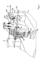
- FIG. 1 part of a table 1 can be seen on which the individual stick heads 2 are arranged.
- a complete embroidery head 2 is shown in FIG. 1, and a further embroidery head is indicated.
- All embroidery heads 2 are driven by a continuous main drive shaft 3.
- a coupling 5 is driven by this main drive shaft 3 via a chain or a toothed belt 4, which is connected on the one hand via a crank pin 5a to a toothed belt wheel 4a and on the other hand via a pin 6a to a rocker arm 6 which is pivotably mounted on a bearing block 7.
- a drive rod 8 is articulated on the coupling 5, the front end of which is connected to a drive arm 9, which in turn is fixed in a rotationally fixed manner on a continuous drive shaft 10.
- This continuous drive shaft 10 which connects all of the embroidery heads 2 to one another, is driven by the rotating main drive shaft 3 with the aid of the transmission members described above in such a way that the drive shaft 10 executes a reciprocating movement.
- the exact association with this oscillating movement of the drive shaft 10 to the continuous rotary movement of the main drive shaft 3 can be adjusted in a simple manner in that the second toothed belt wheel 4b is rotatably attached to the main drive shaft 3.
- each embroidery site ie each embroidery head 2
- each embroidery site comprises a total of five needle bars 11, each of which is provided with a needle 12.
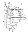
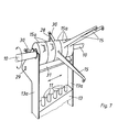
- the needle bars 11 are slidably supported in their longitudinal direction in a needle bar slide 13, a part of which is shown in FIGS. 2 and 7.
- a needle bar carriage 13 By moving this needle bar carriage 13 transversely to the embroidery direction of the needle bars 11, a needle bar can be moved into a working position in which it is connected to the main drive shaft 3 via suitable gear elements, whereas the other needle bars 11 are held in a rest position.
- Fig. 1 is the middle of the five needles rods 11 in the working position, as can be seen from their position above the tap hole in the throat plate 14.
- Each needle bar 11 is assigned a thread take-up lever 15, which is simultaneously transferred into its working position with the needle bars 11 and is coupled to the drive shaft 10.
- the storage and the drive of this thread take-up lever 15 are explained below using various exemplary embodiments.
- all the thread transmitter levers 15 are freely rotatable and axially displaceable on the continuous drive shaft 10 common to all embroidery points.
- the thread take-up levers 15 are supported with cylindrical bearing bushes 16 on the cylindrical outer surface of the drive shaft 10. They are arranged axially displaceably on the drive shaft 10 in a region which is limited by two bearing brackets 17 by the Drive shaft 10 is rotatably supported by bearings 17a.
- the axial displacement of the thread take-up lever 15 on the drive shaft 10 takes place by means of driver plates 13a, which are arranged on the needle bar slide 13 according to FIGS. 2 and 7.
- driver plates 13a which are arranged on the needle bar slide 13 according to FIGS. 2 and 7.
- a driver 18, which is firmly connected to the drive shaft 10 in the axial and radial direction, is used to drive the thread transmitter lever 15 in the working position.
- this driver 18 is arranged at the end of a bridge arm 19, which is on the side outside of Displacement range of the thread take-up lever 15 is firmly connected to the drive shaft 10 by a bearing disc 20.
- the driver 18 executes a movement corresponding to the reciprocating rotational movement of the drive shaft 10.
- the driver 18 engages in a groove 21 which is formed in the cylindrical outer surface of the bearing part 15a of each thread take-up lever 15. This groove 21 can be seen both in FIG. 2 and in FIG. 4.
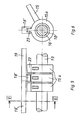
- FIGS. 5 and 6 shows a modified construction.
- the driver 18 'arranged at the end of the bridge arm 19 is fork-shaped in order to cooperate with a strip-shaped elevation 23 on the cylindrical jacket surface of the bearing parts 15a of the thread take-up lever 15.
- the retaining strips, not shown in FIGS The thread take-up lever in the rest position is accordingly designed with a fork-shaped cross section.
- Fig. 5 is finally indicated by dash-dotted lines that instead of a one-sided bridge arm 19, a bridge 19 'can be used, which is connected at both ends, for example by means of a bearing plate 20 with the drive shaft 10.
- FIG. 7 to 10 a third embodiment is shown.
- the illustrations in turn show five thread take-up levers 15, which are assigned to a corresponding number of needle bars 11 arranged in a needle bar slide 13.
- the thread take-up levers 15 have cylindrical bearing parts 15a, with which they are freely rotatable and displaceable in the axial direction on the drive shaft 10.
- each thread transmitter lever 15 is provided in its bearing surface resting on the drive shaft 10 with an axially extending groove 24 into which a driver 25 connected to the drive shaft 10 can engage.
- This driver has a maximum axial extent corresponding to the width of a thread take-up lever 15; however, it can also be made considerably narrower, as can be seen in FIG. 10.
- the driver 25 can be pressed against the force of a return spring 26 in the radial direction into the interior of the drive shaft 10, so that there is the possibility of making an axial displacement of the thread take-up lever 15 on the drive shaft 10 without the drive shaft 10 having to be stopped in a certain position.
- both the end faces of the thread take-up lever 15 and the drive 25 are provided with guide bevels running in the axial direction.
- the driver 25 is pressed back against the force of the return spring 26 into the interior of the drive shaft 10 ', provided the driver 25 does not immediately enter the groove 24 during an axial displacement of the thread take-up lever 15, but first on the end face of the bearing part 15a of the respective thread lever 15 strikes.
- the thread take-up levers 15 which are in the rest position are not fixed in a form-fitting manner on holding strips, but are pulled into the rest position by a return spring 28.
- these return springs 28 act on the one hand on a bearing pin 29 between the bearing brackets 17 and on the other hand on a pin 30 which is inserted into the bearing part 15a of the thread take-up lever 15.
- This pin 30 comes to rest in the rest position on a stop bar 31, which also extends between the bearing brackets 17, so that in this embodiment, the thread take-up lever 15, which is not in the working position, is reliably held in the rest position.
- the fourth embodiment shown in FIGS. 11 and 12 is correct with respect to the drive and the storage of the thread take-up lever 15 in accordance with the first embodiment 2 to 4 correspond. It differs from this embodiment in that the bearing plate 20 carrying the bridge arm 19 is not fixed, but rotatably arranged on the drive shaft 10.
- This bearing disc 20 carries a pawl 33 which can be pivoted about a bearing pin 32 and which is loaded by a compression spring 34.
- the pawl arm 33a of the two-armed pawl 33 works together with a driver bar 35a, which is fastened on a bearing piece 35 fastened on the drive shaft 10.
- a switching magnet 36 is provided, the plunger 36a of which, provided with a roller 36b, acts on the switching arm 33b of the pawl 33.
- the bearing disc 20 can be decoupled from the bearing piece 35 by pivoting the pawl 33 by the switching magnet 36 against the force of the compression spring 34, so that no specific position for an axial displacement of the thread take-up lever 15 on the one hand the drive shaft 10 and on the other hand the thread take-up lever 15 must be waited for, neither for the uncoupling nor for the coupling process.
- a return spring 37 is provided in order to bring the bearing disk 20 with the pawl 33 into a predetermined starting position after the coupling process.
Landscapes
- Engineering & Computer Science (AREA)
- Textile Engineering (AREA)
- Sewing Machines And Sewing (AREA)
Applications Claiming Priority (2)
| Application Number | Priority Date | Filing Date | Title |
|---|---|---|---|
| DE19838328054U DE8328054U1 (de) | 1983-09-30 | 1983-09-30 | Stickmaschine |
| DE8328054U | 1983-09-30 |
Publications (4)
| Publication Number | Publication Date |
|---|---|
| EP0137996A2 true EP0137996A2 (fr) | 1985-04-24 |
| EP0137996A3 EP0137996A3 (en) | 1985-07-10 |
| EP0137996B1 EP0137996B1 (en) | 1987-01-28 |
| EP0137996B2 EP0137996B2 (fr) | 1990-09-05 |
Family
ID=6757538
Family Applications (1)
| Application Number | Title | Priority Date | Filing Date |
|---|---|---|---|
| EP84110244A Expired - Lifetime EP0137996B2 (fr) | 1983-09-30 | 1984-08-29 | Machine à broder |
Country Status (3)
| Country | Link |
|---|---|
| EP (1) | EP0137996B2 (fr) |
| DE (2) | DE8328054U1 (fr) |
| GR (1) | GR80268B (fr) |
Cited By (1)
| Publication number | Priority date | Publication date | Assignee | Title |
|---|---|---|---|---|
| EP2801651A1 (fr) * | 2013-05-10 | 2014-11-12 | Chee Siang Industrial Co., Ltd. | Mécanisme de routage de fil pour machine à coudre |
Family Cites Families (2)
| Publication number | Priority date | Publication date | Assignee | Title |
|---|---|---|---|---|
| US3884165A (en) * | 1973-05-18 | 1975-05-20 | Ikuo Tajima | Needle-bar and take-up lever selection apparatus for embroidery machine |
| DE2938903C3 (de) * | 1979-09-26 | 1982-02-25 | Pfaff Industriemaschinen Gmbh, 6750 Kaiserslautern | Stickmaschine mit Fadenwechseleinrichtung |
-
1983
- 1983-09-30 DE DE19838328054U patent/DE8328054U1/de not_active Expired
-
1984
- 1984-08-29 EP EP84110244A patent/EP0137996B2/fr not_active Expired - Lifetime
- 1984-08-29 DE DE8484110244T patent/DE3462275D1/de not_active Expired
- 1984-08-31 GR GR80268A patent/GR80268B/el unknown
Cited By (1)
| Publication number | Priority date | Publication date | Assignee | Title |
|---|---|---|---|---|
| EP2801651A1 (fr) * | 2013-05-10 | 2014-11-12 | Chee Siang Industrial Co., Ltd. | Mécanisme de routage de fil pour machine à coudre |
Also Published As
| Publication number | Publication date |
|---|---|
| EP0137996A3 (en) | 1985-07-10 |
| DE3462275D1 (en) | 1987-03-05 |
| DE8328054U1 (de) | 1983-12-29 |
| GR80268B (en) | 1984-11-29 |
| EP0137996B2 (fr) | 1990-09-05 |
| EP0137996B1 (en) | 1987-01-28 |
Similar Documents
| Publication | Publication Date | Title |
|---|---|---|
| DE19511949A1 (de) | Strickmaschine und Fadenwechselvorrichtung | |
| DE19805924A1 (de) | Getriebe | |
| DE2727833C2 (de) | Schiebemechanismus einer Schalteinrichtung für ein Kraftfahrzeuggetriebe | |
| DE2749700B2 (de) | Vorrichtung zum zeitweisen Unterbrechen der Sticknadelbewegung an Stickoder Nähmaschinen | |
| DE4212272C2 (de) | Überwendlich-Nähmaschine | |
| DE3010840C2 (de) | Vorrichtung zum Antrieb mindestens einer Nadelstange an Stick- oder Nähmaschinen | |
| DE2550831C2 (de) | Antriebskupplung | |
| DE102005045277B4 (de) | Nadelstangenmechanismus einer Zwillingsnadel-Nähmaschine | |
| DE3528120C1 (de) | Kraftbetaetigtes Spannfutter | |
| DE69321162T2 (de) | Vorrichtung zur Bewegung von Fadenführerkasten für eine Flachstrickmaschine | |
| DE3200290C2 (de) | Stickmaschine | |
| DE2632859C2 (de) | Nadelauswahleinrichtung für eine Strickmaschine | |
| DE2926929C2 (de) | Mustergetriebe für Kettenwirkmaschinen o.dgl. | |
| EP0137996A2 (fr) | Machine à broder | |
| DE3346246C2 (de) | Kettenwirkmaschine, insbesondere Häkelgalonmaschine | |
| DE836593C (de) | Knopfloch-Naehmaschine | |
| DE2330369C3 (de) | Handstrickapparat | |
| DE7927132U1 (de) | Stickautomat mit mehreren einnadel- stickkoepfen | |
| DE3035704A1 (de) | Vorrichtung zur verstellung des farbwechselschlittens an mehrkopfstickmaschinen | |
| EP0113816B1 (fr) | Procédé et dispositif pour la commande d'une ratière du type rotatif | |
| DE2138158A1 (de) | Schnttschaltvornchtung, insbesondere fur den Typenträgerschhtten bzw. den Wa gen von Druckwerken der Datenverarbeitung | |
| DE69004510T2 (de) | Streckwerk für textile Faserbänder. | |
| DE4032302A1 (de) | Kurvenscheibeneinheit und naehmaschine zur verwendung derselben | |
| DE2055300C3 (de) | Vorrichtung zum Antrieb der Faden fuhrer einer mehrfontungen Strickma schme mit jeweils V förmig angeordneten Nadelbetten | |
| DE19958008C1 (de) | Nähanlage zur Herstellung einer Naht nach vorgegebenem Nahtverlauf |
Legal Events
| Date | Code | Title | Description |
|---|---|---|---|
| PUAI | Public reference made under article 153(3) epc to a published international application that has entered the european phase |
Free format text: ORIGINAL CODE: 0009012 |
|
| AK | Designated contracting states |
Designated state(s): DE FR IT |
|
| PUAL | Search report despatched |
Free format text: ORIGINAL CODE: 0009013 |
|
| RHK1 | Main classification (correction) |
Ipc: D05C 11/16 |
|
| AK | Designated contracting states |
Designated state(s): DE FR IT |
|
| RHK1 | Main classification (correction) |
Ipc: D05C 11/08 |
|
| RTI1 | Title (correction) | ||
| 17P | Request for examination filed |
Effective date: 19850704 |
|
| 17Q | First examination report despatched |
Effective date: 19860424 |
|
| GRAA | (expected) grant |
Free format text: ORIGINAL CODE: 0009210 |
|
| AK | Designated contracting states |
Kind code of ref document: B1 Designated state(s): DE FR IT |
|
| REF | Corresponds to: |
Ref document number: 3462275 Country of ref document: DE Date of ref document: 19870305 |
|
| ITF | It: translation for a ep patent filed | ||
| ET | Fr: translation filed | ||
| PLBI | Opposition filed |
Free format text: ORIGINAL CODE: 0009260 |
|
| 26 | Opposition filed |
Opponent name: MARCO STICKAUTOMATEN-GESELLSCHAFT TRAGESER & CO. Effective date: 19871024 |
|
| PUAH | Patent maintained in amended form |
Free format text: ORIGINAL CODE: 0009272 |
|
| STAA | Information on the status of an ep patent application or granted ep patent |
Free format text: STATUS: PATENT MAINTAINED AS AMENDED |
|
| 27A | Patent maintained in amended form |
Effective date: 19900905 |
|
| AK | Designated contracting states |
Kind code of ref document: B2 Designated state(s): DE FR IT |
|
| ITF | It: translation for a ep patent filed | ||
| ET3 | Fr: translation filed ** decision concerning opposition | ||
| ITTA | It: last paid annual fee | ||
| PGFP | Annual fee paid to national office [announced via postgrant information from national office to epo] |
Ref country code: DE Payment date: 19970714 Year of fee payment: 14 |
|
| PGFP | Annual fee paid to national office [announced via postgrant information from national office to epo] |
Ref country code: FR Payment date: 19970717 Year of fee payment: 14 |
|
| PG25 | Lapsed in a contracting state [announced via postgrant information from national office to epo] |
Ref country code: FR Free format text: LAPSE BECAUSE OF NON-PAYMENT OF DUE FEES Effective date: 19990430 |
|
| PG25 | Lapsed in a contracting state [announced via postgrant information from national office to epo] |
Ref country code: DE Free format text: LAPSE BECAUSE OF NON-PAYMENT OF DUE FEES Effective date: 19990601 |
|
| REG | Reference to a national code |
Ref country code: FR Ref legal event code: ST |