EP0138004A2 - Verfahren zum Entfernen des metallischen Niederschlages von der nichtplattierten Oberfläche eines einseitig plattierten Metallbades - Google Patents
Verfahren zum Entfernen des metallischen Niederschlages von der nichtplattierten Oberfläche eines einseitig plattierten Metallbades Download PDFInfo
- Publication number
- EP0138004A2 EP0138004A2 EP84110346A EP84110346A EP0138004A2 EP 0138004 A2 EP0138004 A2 EP 0138004A2 EP 84110346 A EP84110346 A EP 84110346A EP 84110346 A EP84110346 A EP 84110346A EP 0138004 A2 EP0138004 A2 EP 0138004A2
- Authority
- EP
- European Patent Office
- Prior art keywords
- plated
- metal strip
- anode
- supplementary
- metal
- Prior art date
- Legal status (The legal status is an assumption and is not a legal conclusion. Google has not performed a legal analysis and makes no representation as to the accuracy of the status listed.)
- Withdrawn
Links
Images


Classifications
-
- C—CHEMISTRY; METALLURGY
- C25—ELECTROLYTIC OR ELECTROPHORETIC PROCESSES; APPARATUS THEREFOR
- C25F—PROCESSES FOR THE ELECTROLYTIC REMOVAL OF MATERIALS FROM OBJECTS; APPARATUS THEREFOR
- C25F5/00—Electrolytic stripping of metallic layers or coatings
-
- C—CHEMISTRY; METALLURGY
- C25—ELECTROLYTIC OR ELECTROPHORETIC PROCESSES; APPARATUS THEREFOR
- C25F—PROCESSES FOR THE ELECTROLYTIC REMOVAL OF MATERIALS FROM OBJECTS; APPARATUS THEREFOR
- C25F7/00—Constructional parts, or assemblies thereof, of cells for electrolytic removal of material from objects; Servicing or operating
-
- Y—GENERAL TAGGING OF NEW TECHNOLOGICAL DEVELOPMENTS; GENERAL TAGGING OF CROSS-SECTIONAL TECHNOLOGIES SPANNING OVER SEVERAL SECTIONS OF THE IPC; TECHNICAL SUBJECTS COVERED BY FORMER USPC CROSS-REFERENCE ART COLLECTIONS [XRACs] AND DIGESTS
- Y10—TECHNICAL SUBJECTS COVERED BY FORMER USPC
- Y10S—TECHNICAL SUBJECTS COVERED BY FORMER USPC CROSS-REFERENCE ART COLLECTIONS [XRACs] AND DIGESTS
- Y10S204/00—Chemistry: electrical and wave energy
- Y10S204/07—Current distribution within the bath
Definitions
- the present invention relates to a process for electrolytically removing metal deposit from a non-plated surface of a single surface-plated metal strip.
- the present invention relates to an improved process for electrolytically removing metal deposit from a non-plated surface of a single surface-plated metal strip while preventing the undesirable stripping of portions of a plating layer on the plated surface of the single surface-plated steel strip.
- a metal strip for example, a steel strip is single surface-plated with a metal in an electrolytic plating liquid, usually the non-plated surface of the metal strip is undesirably soiled with metal deposits.
- the metal deposit on the non-plated surface is intentionally produced so that the non-plated surface is protected from electrolytic etching by the electrolytic plating liquid.
- the metal deposit must be removed from the non-plated surface of the metal strip by means of an electrolytic treatment.
- portions of plated metal layer located at side edge portions of the plated surface of the metal strip are stripped in the form of continuous belts extending along the side edges of the metal strip.
- An object of the present invention is to provide a process for electrolytically removing metal deposit from a non-plated surface of a single surface-plated metal strip while preventing undesirable stripping of portions of the plated metal layer at side edge portions of the plated surface of the metal strip.
- the above-mentioned object can be attained by the process of the present invention which comprises bringing, within an electrolytic liquid, a single surface-plated metal strip which serves as an anode plate, into.a location at which the non-plated surface of the anode single surface-plated metal strip faces in parallel to and is spaced from a cathode plate; applying a principal voltage between the anode metal strip and the the cathode plate to electrolytically remove / metal deposit from the non-plated surface; which process is characterized in that supplementary anode plates are arranged, within the electrolytic liquid, in locations such that the supplementary anode plates face in parallel to and are spaced from side edge portions of the plated surface of the anode metal strip; and then, while the principal voltage is applied between the anode metal strip and the cathode plate, a supplementary voltage is applied between the supplementary anode plates and the metal strip, the electric potential of the supplementary anode plate being higher than that of the metal strip, thereby preventing undesirable stripping of portions
- a surface of a metal strip for example, a steel strip
- a metal strip is single surface-plated with a metal in an electrolytic plating liquid
- undesirable deposits of the metal produced on the non-plated opposite surface of the metal strip can be removed by means of an electrolytic treatment.
- This electrolytic treatment can be carried out by using a conventional electrolytic apparatus, for example, as shown in Figs. 1 and 2.
- an electrolytic treatment vessel 1 contains an electrolytic liquid 2.
- a single surface-plated metal strip 3 and a cathode plate 4 are arranged so that a non-plated surface 5 of the metal strip 3 faces in parallel to and is spaced from the cathode plate 4.
- the metal strip 3 serves as an anode.
- a voltage is then applied from an electric source 6 between the anode metal strip 3 and the cathode plate 4 so as to remove metal deposit on the non-plated surface 5.
- This electrolytic treatment can be continuously carried out by a conventional apparatus, for example, as shown in Fig. 2.
- a vessel 21 contains an electrolytic liquid 22 which is supplied from a electrolytic liquid tank 23 through a pump 24, conduits 25, 26, and 27, and, nozzles 28 and 29. A portion of the electrolytic liquid 22 overflows from the vessel 21 and is recycled into the tank 23 through an overflow through 30 and conduit 31.
- a metal strip 32 is introduced into the vessel 21 through a guide roll 33, moves through a guide roll 34, and is withdrawn from the vessel 21 through a guide roll 35.
- two cathode plates 36 and 37 are arranged at a location such that the cathode plates 36 and 37 face in parallel to and are spaced from a non-plated surface of the metal strip 32. A voltage is applied to between the metal strip 32 and the cathode plates 36 and 37 through the guide rolls 33 and 35 which are in contact with the metal strip 32.
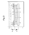
- supplementary anode plates are arranged in the electrolytic liquid in such a manner that each of the supplementary anode plates faces in parallel to and is spaced from the corresponding side edge portion of the plated surface of the single surface-plated metal strip, and then while a principal voltage is applied between the anode metal strip and the cathode plate, a supplementary voltage is applied between each supplementary anode plate and the metal strip, the supplementary anode plate having a higher electric potential than that of the metal strip.
- a vessel 1 contains an electrolytic liquid 2.
- an electrolytic liquid 2 Within this electrolytic liquid 2, a single surface-plated metal strip 3 and a cathode plate 4 are arranged in a relationship to each other such that the non-plated surface 5 of the metal strip 3 is in parallel to and faces the cathode plate 4 in such a manner as to form a space therbetween.
- the cathode plate 4 is preferably made from a material insoluble in the electrolytic liquid used.
- Supplementary anode plates 11 and 12 are arranged in such a manner that the supplementary anode plates 11 and 12 face and are spaced from side edge portions 7a and 7b of the plated surface 8 of the metal strip 3 in parallel to each other, as indicated in Fig. 3.
- a supplementary voltage is applied from an electric source 13 between the supplementary anode plates 11 and_12 and the cathode plate 4. It is important that the electric potential of each supplementary anode plate be maintained higher than that of the metal strip.
- the principal voltage causes an electric current to pass between the non-plated surface 5 of the metal strip 3 and the cathode plate 4 in the direction indicated by arrow A, so as to remove metal deposits from the non-plated surface 5.
- a supplementary voltage creates supplementary electric currents flowing between the additional anode plates 11 and 12 and the side edge portions 7a and 7b of the plated surface 8 of the metal strip 3 in the direction indicated by arrows C and D. These currents C and D are effective for preventing the creation of undesirable swirl currents around the side edge portions 7a and 7b of the metal strip 3 and therefore, for preventing stripping of portions of the plated metal layer 9 located at the side edge portions of the plated surface 8.
- the electrolytic liquid contains at least one electrolyte, for example, NaH 2 PO 4 ⁇ 2H 2 O.
- the principal voltage causes a principal electric current to be produced preferably in a current density 2 of 30 to 100 A/dm , between the non-plated surface of the metal strip 3 and the cathode plate 4.
- the supplementary voltage causes a supplementary electric current to be produced preferably in an entire current of 150 to 300 A.
- the principal voltage is adjusted so as to create a principal current having a current with the density necessary for completely removing the metal deposit from the non-plated surface of the metal strip 3.
- the supplementary voltage is controlled, in response to the necessary current density of the principal current, to a value that will produce the necessary entire current for preventing the creation of undesirable swirl currents around the side edge portions 7a, 7b of the metal strip; the intensity of the swirl currents depending upon the value of the principal current density applied.
- the electrolytic treatment in accordance with the present invention is carried out preferably at a temperature of from 10°C to 70°C for 0.5 seconds to 5 seconds.
- the metal strip was moved at a velocity of 100 m/min through an electrolytic liquid containing 200 g/l of NaH 2 P0 4 and having a pH of 5 and a temperature of 40°C, in such a manner that the non-plated surface of the steel strip is in parallel to and faces a cathode plate having a length of 1500 mm and is spaced 25 mm from the cathode plate, and two supplementary anode plates each having a length of 1500 mm were arranged so that the supplementary anode plates face the side edge portions having a width of 15 mm of the plated surface of the steel strip and are spaced 10 mm from the plated surface.
- a principal voltage of 40 volts was applied between the cathode plate and the steel strip so as to produce an electric current at a current density of 35 A/dm 2 between them.
- a supplementary voltage of 18 volts was applied between the supplementary anode plates and the metal strip so as to create 200 A of an entire current between them.
- Example 2 The same procedures as those described in Example 1 were applied to a single surface-plated steel strip with a plated surface thereof having 23 g/m 2 of a plated alloy layer consisting of 10 parts by weight of iron and 90 parts by weight of zinc, and a non-plated surface thereof soiled with 0.5 g/m 2 of metal deposit consisting of 10 parts by weight of iron and 90 parts by weight of zinc.
- a surface of a steel strip was electrolytically plated with a base alloy layer consisting of 15 parts by weight of iron and 85 parts by weight of iron, and then with an upper alloy layer consisting of 85 parts by weight of iron and 15 parts by weight of zinc, the sum of the weights of the base and upper alloy layer being 23 g/m 2 .
- the non-plated surface of the steel strip was soiled with 0.6 g/m 2 of metal deposit consisting of 20 parts by weight of iron and 80 parts by weight of zinc.
- Example 2 The same electrolytic treatment as that described in Example 1 was applied to the above-mentioned single surface-plated steel strip, except that the principal currnet density was 60 A/dm 2 , the entire supplementary current was 240 A, and the width of each side edge portion of the plated surface of the steel strip, which portion faced in parallel to each corresponding supplementary anode plate, was 20 mm.
- the metal deposit on the non-plated surface was completely removed without stripping the plated metal layer from the plated surface of the steel strip.
- Example 3 The same procedures as those described in Example 3 were carried out except that the amount of the metal deposit was 0.7 g/m 2 , the principal current density was 100 A/dm 2 , entire supplementary current was 280 A, and the width of the side edge portion of the metal strip to which the supplementary current was applied was 25 mm.
- the metal deposit was completely removed from the non-plated surface, without stripping the plated metal layer on the plated surface of the steel strip.
- Example 3 The same procedures as those described in Example 3 were carried out except that the amount of the metal deposit on the non-plated surface was 0.3 g/m 3 , the principal current density was 30 A/dm2, 'the entire supplementary current was 150 A, and the width of each side edge portion of the plated surface to which the supplementary current was applied, was 100 mm.
- the metal deposit was completely removed from the non-plated surface of the steel strip without stripping the plated metal layer from the plated surface of the steel strip.
- Example 2 The same procedures as those described in Example 1 were carried out except that no supplementary voltage was applied between the supplementary anode plates and the metal strip.
- Example 2 The same procedures as those described in Example 1 were carried out except that the supplementary anode plates were moved outward from the steel strip so that the supplementary anode did not face the plated surface of steel strip.
Landscapes
- Chemical & Material Sciences (AREA)
- Engineering & Computer Science (AREA)
- Chemical Kinetics & Catalysis (AREA)
- Electrochemistry (AREA)
- Materials Engineering (AREA)
- Metallurgy (AREA)
- Organic Chemistry (AREA)
- Electroplating Methods And Accessories (AREA)
Applications Claiming Priority (2)
| Application Number | Priority Date | Filing Date | Title |
|---|---|---|---|
| JP58160397A JPS6052599A (ja) | 1983-09-02 | 1983-09-02 | メツキ鋼板のメツキ金属電解剥離方法 |
| JP160397/83 | 1983-09-02 |
Publications (2)
| Publication Number | Publication Date |
|---|---|
| EP0138004A2 true EP0138004A2 (de) | 1985-04-24 |
| EP0138004A3 EP0138004A3 (de) | 1987-03-25 |
Family
ID=15714061
Family Applications (1)
| Application Number | Title | Priority Date | Filing Date |
|---|---|---|---|
| EP84110346A Withdrawn EP0138004A3 (de) | 1983-09-02 | 1984-08-30 | Verfahren zum Entfernen des metallischen Niederschlages von der nichtplattierten Oberfläche eines einseitig plattierten Metallbades |
Country Status (4)
| Country | Link |
|---|---|
| US (1) | US4548685A (de) |
| EP (1) | EP0138004A3 (de) |
| JP (1) | JPS6052599A (de) |
| CA (1) | CA1230312A (de) |
Cited By (1)
| Publication number | Priority date | Publication date | Assignee | Title |
|---|---|---|---|---|
| DE3924263A1 (de) * | 1988-12-07 | 1990-06-13 | Chemcut Corp | Verfahren und vorrichtung zum elektrolytischen entfernen von schutzschichten von einem metallagensubstrat |
Families Citing this family (3)
| Publication number | Priority date | Publication date | Assignee | Title |
|---|---|---|---|---|
| JPS62188800A (ja) * | 1986-02-14 | 1987-08-18 | Nippon Chikasui Kaihatsu Kk | 無散水消雪用鋼管の製造方法 |
| US5217586A (en) * | 1992-01-09 | 1993-06-08 | International Business Machines Corporation | Electrochemical tool for uniform metal removal during electropolishing |
| CN103147115B (zh) * | 2013-03-22 | 2016-04-20 | 中冶南方工程技术有限公司 | 冷轧带钢电解清洗用电极 |
Family Cites Families (5)
| Publication number | Priority date | Publication date | Assignee | Title |
|---|---|---|---|---|
| US3970537A (en) * | 1973-07-11 | 1976-07-20 | Inland Steel Company | Electrolytic treating apparatus |
| US3959099A (en) * | 1975-06-18 | 1976-05-25 | Inland Steel Company | Electrolytic method of producing one-side-only coated steel |
| US3989604A (en) * | 1975-10-15 | 1976-11-02 | National Steel Corporation | Method of producing metal strip having a galvanized coating on one side |
| US3988216A (en) * | 1975-10-15 | 1976-10-26 | National Steel Corporation | Method of producing metal strip having a galvanized coating on one side while preventing the formation of a zinc deposit on cathode means |
| US4464232A (en) * | 1982-11-25 | 1984-08-07 | Sumitomo Metal Industries, Lt. | Production of one-side electroplated steel sheet |
-
1983
- 1983-09-02 JP JP58160397A patent/JPS6052599A/ja active Granted
-
1984
- 1984-08-23 US US06/643,451 patent/US4548685A/en not_active Expired - Fee Related
- 1984-08-30 EP EP84110346A patent/EP0138004A3/de not_active Withdrawn
- 1984-08-31 CA CA000462278A patent/CA1230312A/en not_active Expired
Cited By (2)
| Publication number | Priority date | Publication date | Assignee | Title |
|---|---|---|---|---|
| DE3924263A1 (de) * | 1988-12-07 | 1990-06-13 | Chemcut Corp | Verfahren und vorrichtung zum elektrolytischen entfernen von schutzschichten von einem metallagensubstrat |
| DE3924263C2 (de) * | 1988-12-07 | 2002-07-18 | Chemcut Corp | Verfahren und Vorrichtung zur elektrolytischen Entfernung von Schutzschichten von Metalllagen |
Also Published As
| Publication number | Publication date |
|---|---|
| US4548685A (en) | 1985-10-22 |
| JPS62240B2 (de) | 1987-01-06 |
| JPS6052599A (ja) | 1985-03-25 |
| CA1230312A (en) | 1987-12-15 |
| EP0138004A3 (de) | 1987-03-25 |
Similar Documents
| Publication | Publication Date | Title |
|---|---|---|
| US4568431A (en) | Process for producing electroplated and/or treated metal foil | |
| US4549950A (en) | Systems for producing electroplated and/or treated metal foil | |
| CA2020638A1 (en) | Continuous electroplating of conductive foams | |
| US3803013A (en) | Electrolytic plating apparatus and method | |
| US5281325A (en) | Uniform electroplating of printed circuit boards | |
| KR100487646B1 (ko) | 금속띠판의전해산세척방법및장치 | |
| US3970537A (en) | Electrolytic treating apparatus | |
| CA1223840A (en) | Process of continuously electrodepositing on strip metal on one or both sides | |
| US3374159A (en) | Marking of steel strip electrolytically using electrolyte adhering to the strip | |
| US3928152A (en) | Method for the electrolytic recovery of metal employing improved electrolyte convection | |
| CA2384244A1 (en) | Method and device for the electrolytic treatment of electrolytically conducting structures which are insulated from each other | |
| US4548685A (en) | Process for electrolytically removing metal deposit from a non-plated surface of a single surface-plated metal strip | |
| US4652346A (en) | Apparatus and process for the continuous plating of wide delicate metal foil | |
| ES8202597A1 (es) | Dispositivo para la metalizacion por electrolisis | |
| PL123151B1 (en) | Cathode for electrochemically refining of the copper | |
| US3959099A (en) | Electrolytic method of producing one-side-only coated steel | |
| EP0054302B1 (de) | Verfahren und Vorrichtung zur kontinuierlichen elektrolytischen Behandlung eines Metallbandes unter Verwendung unlöslicher horizontaler Elektroden | |
| US4532014A (en) | Laser alignment system | |
| KR910007161B1 (ko) | 전기도금된 금속 박막 제조 시스템 | |
| US4248674A (en) | Anodizing method and apparatus | |
| US4505785A (en) | Method for electroplating steel strip | |
| US2399964A (en) | Method of electrogalvanizing | |
| US2313422A (en) | Method of pickling metallic strip | |
| US3715286A (en) | Electrorefined nickel of controlled size | |
| KR960004269B1 (ko) | 금속스트립의 무흠집 전기도금방법 |
Legal Events
| Date | Code | Title | Description |
|---|---|---|---|
| PUAI | Public reference made under article 153(3) epc to a published international application that has entered the european phase |
Free format text: ORIGINAL CODE: 0009012 |
|
| AK | Designated contracting states |
Designated state(s): DE FR GB IT |
|
| PUAL | Search report despatched |
Free format text: ORIGINAL CODE: 0009013 |
|
| AK | Designated contracting states |
Kind code of ref document: A3 Designated state(s): DE FR GB IT |
|
| STAA | Information on the status of an ep patent application or granted ep patent |
Free format text: STATUS: THE APPLICATION IS DEEMED TO BE WITHDRAWN |
|
| 18D | Application deemed to be withdrawn |
Effective date: 19870928 |
|
| RIN1 | Information on inventor provided before grant (corrected) |
Inventor name: SUEMITSU, YUKIMASAC/O NAGOYA WORKS Inventor name: NAKA, RYOICHIC/O NAGOYA WORKS Inventor name: NAKAJIMA, KAZUTSUGUC/O NAGOYA WORKS Inventor name: GOSHI, HIROOC/O NAGOYA WORKS |