EP0138008B1 - Verfahren und Anordnung zum Einstellen und Regeln der Frequenz eines Signalgenerators - Google Patents
Verfahren und Anordnung zum Einstellen und Regeln der Frequenz eines Signalgenerators Download PDFInfo
- Publication number
- EP0138008B1 EP0138008B1 EP84110371A EP84110371A EP0138008B1 EP 0138008 B1 EP0138008 B1 EP 0138008B1 EP 84110371 A EP84110371 A EP 84110371A EP 84110371 A EP84110371 A EP 84110371A EP 0138008 B1 EP0138008 B1 EP 0138008B1
- Authority
- EP
- European Patent Office
- Prior art keywords
- voltage
- frequency
- deviation
- controlled oscillator
- vco
- Prior art date
- Legal status (The legal status is an assumption and is not a legal conclusion. Google has not performed a legal analysis and makes no representation as to the accuracy of the status listed.)
- Expired
Links
Images
Classifications
-
- H—ELECTRICITY
- H03—ELECTRONIC CIRCUITRY
- H03L—AUTOMATIC CONTROL, STARTING, SYNCHRONISATION OR STABILISATION OF GENERATORS OF ELECTRONIC OSCILLATIONS OR PULSES
- H03L7/00—Automatic control of frequency or phase; Synchronisation
- H03L7/06—Automatic control of frequency or phase; Synchronisation using a reference signal applied to a frequency- or phase-locked loop
- H03L7/16—Indirect frequency synthesis, i.e. generating a desired one of a number of predetermined frequencies using a frequency- or phase-locked loop
- H03L7/18—Indirect frequency synthesis, i.e. generating a desired one of a number of predetermined frequencies using a frequency- or phase-locked loop using a frequency divider or counter in the loop
- H03L7/181—Indirect frequency synthesis, i.e. generating a desired one of a number of predetermined frequencies using a frequency- or phase-locked loop using a frequency divider or counter in the loop a numerical count result being used for locking the loop, the counter counting during fixed time intervals
Definitions
- the present invention relates to a method for setting and regulating the frequency of a signal generator with a voltage-controlled oscillator, a measuring stage, at least one counter with the aid of a microprocessor with program memory (PROM) and read-write memory (RAM), in which the Frequency of the voltage-controlled oscillator is counted during a constant gate time generated by the microprocessor, a binary pattern generated by the count is compared with a stored setpoint pattern and the sign and a binary pattern for the magnitude of the deviation are determined therefrom, and in which a switching element Voltage, the polarity of which depends on the sign of the deviation, is applied to an RC element and then to the actuator of the voltage-controlled oscillator.
- PROM program memory
- RAM read-write memory
- a deviation counter is preset with the binary pattern for the magnitude of the deviation and is then gradually reset to zero with the aid of a periodic input signal, that the switching element is closed at the start of this reset and opened at the end of the reset becomes.
- a microprocessor is used for input, control and the target / actual comparison.
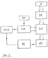
- the measuring frequency is counted by a binary counter (FM), the number of stages of which is determined by the required accuracy.
- the gate time is derived from the reference oscillator of the microprocessor (RF), which is equipped with a highly precise quartz.
- the input (E) can be converted in any form as frequency, number of channels or the like directly by the processor into a binary setpoint (SR), which can then be compared with the measured value (S / V).
- SR binary setpoint
- S / V binary setpoint
- the determined difference and the sign evaluation control a control voltage converter (D / A converter) (KS). This converter in turn regulates the voltage-independent oscillator (VCO) to its set frequency via the loop filter (RC).
- a 20-step counter gives an accuracy of 2 2 °, ie approximately 10 6 .
- the bit pattern obtained from the setpoint / actual value comparison is loaded into a counter.
- This counter is then counted down with the periodic signal from the reference oscillator (RF) until the latter emits a signal when the counter reading reaches zero.
- the time difference from the start of the countdown to the zero crossing of the counter (FM) is a measure of the storage of the actual frequency from the target frequency.
- the amount and direction of the control voltage correction are determined. This is fed to the oscillator via an analog channel switch and subsequent RC element. Only when the frequencies have changed by more than 1 bit due to self-discharge of the RC element, temperature fluctuation or change in the supply voltage, is the readjustment carried out, ie the actual frequency fluctuates by ⁇ 1 bit around the set frequency. In order to keep the circuit complexity small, the same counter was used in successive operations for frequency counting and time difference acquisition.
- the catch range of the frequency control loops constructed according to the invention is extremely large from the frequency zero to the maximum limit frequency of the counter modules, with a correspondingly selected gate time, so that the range essentially depends on the tuning range of the voltage-controlled oscillator.
Landscapes
- Stabilization Of Oscillater, Synchronisation, Frequency Synthesizers (AREA)
- Channel Selection Circuits, Automatic Tuning Circuits (AREA)
- Circuits Of Receivers In General (AREA)
Description
- Die vorliegende Erfindung betrifft ein Verfahren zum Einstellen und Regeln der Frequenz eines Signalgenerators mit einem spannungsgesteuerten Oszillator, einer Messstufe, mindestens einem Zähler unter Zuhilfenahme eines Mikroprozessors mit Programmspeicher (PROM) und Schreib-Lese-Speicher (RAM), bei dem durch die Messstufe die Frequenz des spannungsgesteuerten Oszillators während einer vom Mikroprozessor erzeugten konstanten Torzeit gezählt wird, ein durch die Zählung erzeugtes binäres Muster mit einem gespeicherten Sollwert-Muster verglichen und daraus Vorzeichen und ein binäres Muster für die Grösse der Abweichung bestimmt werden, und bei dem über ein Schaltglied eine Spannung, deren Polarität abhängig ist vom Vorzeichen der Abweichung, auf ein RC-Glied und danach auf das Stellglied des spannungsgesteuerten Oszillators gegeben wird.
- Eine Anordnung zum Durchführen dieses Verfahrens ist bekannt aus der US-A-42 98 988. Dort ist allerdings nicht näher ausgeführt, in welcher Weise das binäre Muster für die Grösse der Abweichung in ein pulsbreites moduliertes Signal umgewandelt wird. Aufgabe der vorliegenden Erfindung ist es daher, weitere Verfahrensschritte für die Verwertung des genannten binären Musters zur Regelung eines einstellbaren Oszillators anzugeben.
- Die Lösug dieser Aufgabe ist dadurch gekennzeichnet, dass mit dem binären Muster für die Grösse der Abweichung ein Abweichungs-Zähler voreingestellt und danach mit Hilfe eines periodischen Eingangssignals schrittweise auf Null zurückgesetzt wird, dass bei Beginn dieses Rücksetzens das Schaltglied geschlossen und bei Ende des Rücksetzens geöffnet wird.
- Eine vorteilhafte Weiterbildung und eine Anordnung zum Duchführen des Verfahrens sind in weiteren Ansprüchen beschrieben.
- Die Erfindung soll jetzt anhand der Figur näher erläutert werden. Für die Eingabe, Steuerung und den Soll-/Ist-Vergleich wird ein Mikroprozessor eingesetzt. Die Messfrequenz wird durch einen Binärzähler (FM) ausgezählt, dessen Stufenzahl von der geforderten Genauigkeit bestimmt wird. Die Torzeit wird von dem Referenzoszillator des Mikroprozessors (RF) abgeleitet, der mit einem hochgenauen Quarz bestückt ist. Die Eingabe (E) kann in beliebiger Form als Frequenz, Kanalzahl oder ähnliches vom Prozessor direkt in einen binären Sollwert umgerechnet werden (SR), der dann mit dem Messwert verglichen werden kann (S/V). Der ermittelte Differenzbetrag und die Vorzeichenauswertung steuern einen Regelspannungskonverter (D/A-Konverter) (KS). Dieser Konverter regelt seinerseits den spannungsunabhängigen Oszillator (VCO) über das Schleifenfilter (RC) auf seine Sollfrequenz. Will man die Genauigkeit über den Faktor 103 treiben, benötigt man einen A/D-Wandler mit höherer als der üblichen Auflösung. Zum Beispiel ergibt ein 20-stufiger Zähler eine Genauigkeit von 22°, d. h. angenähert 106. Es wurde deshalb ein anderer Weg beschritten, um aus dem Differenzbitmuster eine Regelspannung zu gewinnen. Das aus dem Soll-/ Istwert-Vergleich gewonnene Bitmuster wird in einen Zähler geladen. Dieser Zähler wird dann mit dem periodischen Signal des Referenzoszillators (RF) zurückgezählt, bis jener bei Erreichen des Zählerstandes Null ein Signal abgibt. Die Zeitdifferenz vom Start des Rückzählvorganges bis zum Nulldurchgang des Zählers (FM) ist ein Mass für die Ablage der Ist-Frequenz von der Sollfrequenz. Zusammen mit der aus dem Soll-Istwert-Vergleich gewonnenen Vorzeicheninformation bestimmt sich Betrag und Richtung der Regelspannungskorrektur. Diese wird über einen Analogkanalschalter und nachfolgendem RC-Glied dem Oszillator zugeführt. Erst wenn durch Eigenentladung des RC-Gliedes, Temperaturschwankung oder Änderung der Versorgungsspannung die Frequenzen sich um mehr als 1 Bit geändert haben, wird nachgeregelt, d.h. die Istfrequenz schwankt mit ± 1 Bit um die Sollfrequenz. Um den Schaltungsaufwand klein zu halten, wurde für die Frequenzzählung und Gewinnung der Zeitdifferenz der gleiche Zähler in aufeinanderfolgenden Vorgängen verwendet. Der Fangbereich der nach der Erfindung aufgebauten Frequenzregel-Schleifen ist überaus gross von der Frequenz Null bis zur maximalen Grenzfrequenz der Zählerbausteine, bei entsprechend gewählter Torzeit, so dass der Bereich im wesentlichen vom Durchstimmbereich des spannungsgesteuerten Oszillators abhängt.
Claims (3)
Priority Applications (1)
| Application Number | Priority Date | Filing Date | Title |
|---|---|---|---|
| AT84110371T ATE38304T1 (de) | 1983-10-13 | 1984-08-31 | Verfahren und anordnung zum einstellen und regeln der frequenz eines signalgenerators. |
Applications Claiming Priority (2)
| Application Number | Priority Date | Filing Date | Title |
|---|---|---|---|
| DE3337283 | 1983-10-13 | ||
| DE19833337283 DE3337283A1 (de) | 1983-10-13 | 1983-10-13 | Verfahren und anordnung zum einstellen und regeln der frequenz eines signalgenerators |
Publications (3)
| Publication Number | Publication Date |
|---|---|
| EP0138008A2 EP0138008A2 (de) | 1985-04-24 |
| EP0138008A3 EP0138008A3 (de) | 1985-06-12 |
| EP0138008B1 true EP0138008B1 (de) | 1988-10-26 |
Family
ID=6211762
Family Applications (1)
| Application Number | Title | Priority Date | Filing Date |
|---|---|---|---|
| EP84110371A Expired EP0138008B1 (de) | 1983-10-13 | 1984-08-31 | Verfahren und Anordnung zum Einstellen und Regeln der Frequenz eines Signalgenerators |
Country Status (5)
| Country | Link |
|---|---|
| EP (1) | EP0138008B1 (de) |
| AT (1) | ATE38304T1 (de) |
| CA (1) | CA1283955C (de) |
| DE (2) | DE3337283A1 (de) |
| DK (1) | DK489884A (de) |
Families Citing this family (2)
| Publication number | Priority date | Publication date | Assignee | Title |
|---|---|---|---|---|
| US5117756A (en) * | 1989-02-03 | 1992-06-02 | Atlas Powder Company | Method and apparatus for a calibrated electronic timing circuit |
| FR2726921B1 (fr) * | 1994-11-16 | 1997-04-25 | Ela Medical Sa | Procede d'ajustage d'un parametre electrique d'un dispositif electronique, notamment d'un stimulateur ou d'un defibrillateur cardiaque, et dispositif le mettant en oeuvre |
Family Cites Families (5)
| Publication number | Priority date | Publication date | Assignee | Title |
|---|---|---|---|---|
| DE2853842A1 (de) * | 1977-12-14 | 1979-07-19 | Hitachi Ltd | Elektronisch abstimmbarer empfaenger |
| DE2818529A1 (de) * | 1978-04-27 | 1979-10-31 | Philips Patentverwaltung | Abstimmverfahren zum vollautomatischen abstimmen eines fernseh- oder rundfunkempfaengers |
| US4298988A (en) * | 1979-02-08 | 1981-11-03 | Jerrold Electronics Corp. | Digital channel selection and fine tuning system |
| FR2497027B1 (fr) * | 1980-12-23 | 1985-06-14 | Thomson Csf | Dispositif de correction de frequence d'un oscillateur et emetteur-recepteur comportant un tel dispositif |
| JPS5847331A (ja) * | 1981-09-04 | 1983-03-19 | テクトロニクス・インコ−ポレイテツド | 信号発生器 |
-
1983
- 1983-10-13 DE DE19833337283 patent/DE3337283A1/de not_active Withdrawn
-
1984
- 1984-08-31 DE DE8484110371T patent/DE3474891D1/de not_active Expired
- 1984-08-31 EP EP84110371A patent/EP0138008B1/de not_active Expired
- 1984-08-31 AT AT84110371T patent/ATE38304T1/de not_active IP Right Cessation
- 1984-10-12 CA CA000465237A patent/CA1283955C/en not_active Expired - Fee Related
- 1984-10-12 DK DK489884A patent/DK489884A/da not_active Application Discontinuation
Also Published As
| Publication number | Publication date |
|---|---|
| DE3337283A1 (de) | 1985-04-25 |
| DK489884A (da) | 1985-04-14 |
| ATE38304T1 (de) | 1988-11-15 |
| CA1283955C (en) | 1991-05-07 |
| DK489884D0 (da) | 1984-10-12 |
| EP0138008A3 (de) | 1985-06-12 |
| DE3474891D1 (en) | 1988-12-01 |
| EP0138008A2 (de) | 1985-04-24 |
Similar Documents
| Publication | Publication Date | Title |
|---|---|---|
| DE2953597C1 (de) | Vorrichtung zur Ansteuerung von Schrittmotoren bei einer automatischen Pruefvorrichtung | |
| DE3007874C2 (de) | ||
| DE68927799T2 (de) | Keltzuführkontrolleinrichtung für eine Webmaschine | |
| DE2932211C2 (de) | ||
| DE2250389B2 (de) | Zeitnormal, insbesondere für elektronische Uhren, mit einer einen einstellbaren Frequenzteiler steuernden Zeitbasis | |
| DE102020110999A1 (de) | Verfahren zur hochpräzisen Fadenablage eines Fadens beim Wickeln einer Spule | |
| DE3324547C2 (de) | ||
| EP0138008B1 (de) | Verfahren und Anordnung zum Einstellen und Regeln der Frequenz eines Signalgenerators | |
| DE3324205C2 (de) | ||
| DE2512738C2 (de) | Frequenzregler | |
| DE2064513A1 (de) | Nach dem Impulszahlverfahren arbei tender, selbsteichender Analog Digital Umsetzer | |
| EP1586156A2 (de) | Pulsweitenmodularschaltung und verfahren zur ansteuerung einer pulsweitenmodularschaltung | |
| DE3152816C2 (en) | Method and device for controlling an object which is to be regulated | |
| DE1538607A1 (de) | Numerische Werkzeugmaschinen-Steuerung | |
| DE2641501C3 (de) | Abstimmbarer Oszillator hoher Frequenzgenauigkeit und Konstanz | |
| DE1547588C3 (de) | Verfahren zur Erhaltung von Tönen einer gleichschwebend-temperierten Tonleiter | |
| DE2164175C3 (de) | Schaltung zur digitalen Frequenzeinstellung eines in einer Regelschleife liegenden Oszillators | |
| DE3324919C2 (de) | ||
| DE2735031C3 (de) | Phasenregelkreis | |
| EP0347883B1 (de) | Verfahren und Vorrichtung zum Auswuchten von rotierenden Teilen | |
| DE3417816A1 (de) | Programmierbares schaltnetz | |
| DE3312154A1 (de) | Drehzahlregelkreis mit automatischem ausgleich des teilungsfehlers eines impulsgebers | |
| DE2362116C3 (de) | Auf einstellbare Frequenzwerte rastbarer Steuergenerator | |
| EP0050676B2 (de) | Verfahren und Vorrichtung zur Aufrechterhaltung der Eingangssymmetrie eines Gegentakt-Wandlers bei grossen Änderungen der Eingangsspannung | |
| DE2537350B2 (de) | Vorrichtung zum Umwandeln von Daten |
Legal Events
| Date | Code | Title | Description |
|---|---|---|---|
| PUAI | Public reference made under article 153(3) epc to a published international application that has entered the european phase |
Free format text: ORIGINAL CODE: 0009012 |
|
| PUAL | Search report despatched |
Free format text: ORIGINAL CODE: 0009013 |
|
| AK | Designated contracting states |
Designated state(s): AT CH DE LI NL |
|
| AK | Designated contracting states |
Designated state(s): AT CH DE LI NL |
|
| RTI1 | Title (correction) | ||
| 17P | Request for examination filed |
Effective date: 19850621 |
|
| 17Q | First examination report despatched |
Effective date: 19870821 |
|
| GRAA | (expected) grant |
Free format text: ORIGINAL CODE: 0009210 |
|
| AK | Designated contracting states |
Kind code of ref document: B1 Designated state(s): AT CH DE LI NL |
|
| REF | Corresponds to: |
Ref document number: 38304 Country of ref document: AT Date of ref document: 19881115 Kind code of ref document: T |
|
| REF | Corresponds to: |
Ref document number: 3474891 Country of ref document: DE Date of ref document: 19881201 |
|
| PLBE | No opposition filed within time limit |
Free format text: ORIGINAL CODE: 0009261 |
|
| 26N | No opposition filed | ||
| PGFP | Annual fee paid to national office [announced via postgrant information from national office to epo] |
Ref country code: CH Payment date: 19950818 Year of fee payment: 12 |
|
| PGFP | Annual fee paid to national office [announced via postgrant information from national office to epo] |
Ref country code: AT Payment date: 19950824 Year of fee payment: 12 |
|
| PGFP | Annual fee paid to national office [announced via postgrant information from national office to epo] |
Ref country code: NL Payment date: 19960822 Year of fee payment: 13 |
|
| PG25 | Lapsed in a contracting state [announced via postgrant information from national office to epo] |
Ref country code: LI Effective date: 19960831 Ref country code: CH Effective date: 19960831 Ref country code: AT Effective date: 19960831 |
|
| REG | Reference to a national code |
Ref country code: CH Ref legal event code: PL |
|
| PG25 | Lapsed in a contracting state [announced via postgrant information from national office to epo] |
Ref country code: NL Free format text: LAPSE BECAUSE OF NON-PAYMENT OF DUE FEES Effective date: 19980301 |
|
| NLV4 | Nl: lapsed or anulled due to non-payment of the annual fee |
Effective date: 19980301 |
|
| PGFP | Annual fee paid to national office [announced via postgrant information from national office to epo] |
Ref country code: DE Payment date: 19981030 Year of fee payment: 15 |
|
| PG25 | Lapsed in a contracting state [announced via postgrant information from national office to epo] |
Ref country code: DE Free format text: LAPSE BECAUSE OF NON-PAYMENT OF DUE FEES Effective date: 20000601 |