EP0138120A2 - Une armature de soutien pour un réservoir toroidal - Google Patents
Une armature de soutien pour un réservoir toroidal Download PDFInfo
- Publication number
- EP0138120A2 EP0138120A2 EP84111581A EP84111581A EP0138120A2 EP 0138120 A2 EP0138120 A2 EP 0138120A2 EP 84111581 A EP84111581 A EP 84111581A EP 84111581 A EP84111581 A EP 84111581A EP 0138120 A2 EP0138120 A2 EP 0138120A2
- Authority
- EP
- European Patent Office
- Prior art keywords
- tank
- shell
- torus
- supporting structure
- stringers
- Prior art date
- Legal status (The legal status is an assumption and is not a legal conclusion. Google has not performed a legal analysis and makes no representation as to the accuracy of the status listed.)
- Withdrawn
Links
Images
Classifications
-
- B—PERFORMING OPERATIONS; TRANSPORTING
- B64—AIRCRAFT; AVIATION; COSMONAUTICS
- B64D—EQUIPMENT FOR FITTING IN OR TO AIRCRAFT; FLIGHT SUITS; PARACHUTES; ARRANGEMENT OR MOUNTING OF POWER PLANTS OR PROPULSION TRANSMISSIONS IN AIRCRAFT
- B64D37/00—Arrangements in connection with fuel supply for power plant
- B64D37/02—Tanks
- B64D37/06—Constructional adaptations thereof
-
- B—PERFORMING OPERATIONS; TRANSPORTING
- B64—AIRCRAFT; AVIATION; COSMONAUTICS
- B64G—COSMONAUTICS; VEHICLES OR EQUIPMENT THEREFOR
- B64G1/00—Cosmonautic vehicles
- B64G1/22—Parts of, or equipment specially adapted for fitting in or to, cosmonautic vehicles
- B64G1/40—Arrangements or adaptations of propulsion systems
- B64G1/402—Propellant tanks; Feeding propellants
- B64G1/4021—Tank construction; Details thereof
-
- B—PERFORMING OPERATIONS; TRANSPORTING
- B64—AIRCRAFT; AVIATION; COSMONAUTICS
- B64G—COSMONAUTICS; VEHICLES OR EQUIPMENT THEREFOR
- B64G1/00—Cosmonautic vehicles
- B64G1/22—Parts of, or equipment specially adapted for fitting in or to, cosmonautic vehicles
- B64G1/40—Arrangements or adaptations of propulsion systems
- B64G1/402—Propellant tanks; Feeding propellants
- B64G1/4022—Arrangements of tanks in or on spacecraft
Definitions
- the present invention relates to a truss supporting structure for a fluid container and, more particularly, to a truss supporting structure for a toroidal tank that is capable of containing a fluid.
- a toroidal tank construction often allows for the maximum utilization of a flight vehicle's interior space.
- the shape of the toroidal tank usually permits it to fit within the narrow or limited confines of a flight vehicle's fuselage or fuel compartment.
- toroidal tanks particularly of a relatively large size
- a flight vehicle has been restricted due to numerous problems with toroidal tank design and analysis.
- the support provisions on the tank walls which are to support the tank against gravity and inertial loads, cause local stress concentrations that necessitate an increased thickness in the tank shell and, correspondingly, an increase in tank weight.
- Some of these support provisions cause localized buckling by inducing net compressive stresses in the tank walls.
- toroidal tanks increase the internal operating pressure or provide localized stiffening.
- these changes result in weight and cost increases.
- conventional toroidal tanks experience much larger stress levels due to internal pressure than, for example, cylindrical tanks of comparable cross-section.
- the toroidal tank must have increased skin thickness to handle fluid pressure.
- the natural frequencies tend to be low and the internal stresses and deflections of the conventional tank can be highly nonlinear and, consequently, they result in variations in dynamic response rates as a function of load and deflection amplitude. These characteristics can seriously impair both accurate dynamic analysis and dynamic response.
- This along with the low natural frequency will limit the usefulness of the toroidal tank in systems in which the dynamics of the toroidal tank are critical to the dynamic response of the system.
- excessive deflections in the conventional toroidal tank can seriously restrict its usefulness in volume constrained applications.
- the toroidal tank used in flight vehicles requires various types of slosh baffles to limit or restrict the sloshing of fluid within the tank.
- the installment of a separate baffling system within the toroidal tank increases the weight, complexity, and cost of the tank.
- the toroidal tank may fail due to a combination of stress corrosion, fatigue and buckling. A localized failure in this type of structure can rapidly propagate and precipitate total system failure.
- the conventional toroidal tank is usually difficult to handle, test, or attach in position due to its fragility.
- a second problem associated with the low natural frequency of the tank support structure is pogo. Pogo results from coupling between the tank support frequencies and the engine firing characteristics resulting in significant variations in engine thrust, which will significantly decrease the vehicle performance efficiency, and can even result in destruction of the vehicle. Occurrence of either problem can be equally effective in preventing the vehicle from accomplishing its intended mission. To analytically verify freedom from these problems, it is essential that the propellant tank structure be both quite stiff and amenable to linear analysis.
- the present invention obviates these inherent problems and disadvantages associated with various toroidal tank constructions by providing a truss supporting structure for a toroidal tank, especially one used in a flight vehicle, that significantly reduces tank stresses; limits tank shell buckling; reduces the nonlinear response of the tank to stress and deflections; and limits the sloshing of the fluid within the tank.
- the present invention solves these problems without significantly increasing the weight of the tank.
- the present invention provides a method of forming a toroidal tank having a truss supporting structure.
- the method comprises the steps of fabricating the truss supporting structures by first joining a plurality of ring-bulkheads to several stringers to establish a firm framework corresponding to the desired size and shape of the tank.
- One or more slosh baffles are attached to the ring-buckheads and the stringers.
- a tank skin is fit over the framework to form a torus shell of the toroidal tank.
- the present invention also provides a toroidal tank truss supporting structure comprising a toroidal tank having a torus portion capable of containing a fluid or a gas.
- the torus portion has a hollow interior and a torus shell enclosing the hollow interior.
- a plurality of ring-bulkheads are attached to the torus shell to divide the hollow interior into compartments.
- a first number of stringers are each connected to or integral with the torus shell.
- a second number of slosh baffles are each attached to two adjacent ring-bulkheads and to two of the first number of stringers.
- the present invention enhances the usefulness of toroidal tank structures, since it provides for concentrated support forces and also limits system deflections and the nonlinear behavior of tanks to levels that can be rationally neglected in static and dynamic strength and deflection behavior analysis.
- the present invention increases the tank strength and its natural frequencies.
- the truss supporting structure will limit the extent of buckling, and prevent buckling from significantly affecting the integrity of the system. Additionally, the proper selection and detailing of the toroidal tank truss supporting structure will also simultaneously provide a slosh baffling and a crack tear stopper.
- the use of the toroidal tank truss supporting structure also eliminates the need to use various support tools in assembling the tank, since the truss supporting structure provides the requisite framework.
- the truss supporting structures of the present invention avoids the numerous problems associated with previous toroidal tank constructions, and provides a toroidal tank that is more durable and easier to handle during fabrication, testing, and shipping due to this durability.
- the location and sizing of specific internal support members for each . different toroidal tank design application are selected and tailored by the structural engineer to best satisfy the requirements of the specific application.
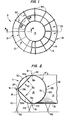
- the toroidal tank 11 includes a torus portion 12 and a central opening 13.
- the torus portion 12 has a hollow interior 14 and a torus shell 15 enclosing the hollow interior 14.
- the torus shell 15 has an exterior surface 20 and an interior surface 21.
- the interior side 21 of the torus shell 15 includes a top portion 22, a bottom portion 23, an outer portion 24, and an inner portion 25.
- top, bottom, outer, and inner portions of the tank are arbitrary designations with respect to the drawings and, in use, the tank may be turned in a number of directions so as to change the relative spatial designations of the tank. Hence, during use, the top portion 22 may actually be the bottom of the tank 11.
- the toroidal tank 11 is usually of the kind used in flight vehicles, such as aircraft and spacecraft, to contain a fluid or a gas, such as a fuel or propellant.
- the toroidal tank can also be of the kind used on the ground to contain various fluids or gases such as cryogenic substances.
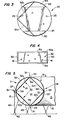
- the torus portion 12 of the toroidal tank 11 has a cross section, as shown in Figure 2, which is substantially circular in shape.
- other cross-sectional shapes such as an ellipse, are acceptable within the scope of the invention.
- the truss supporting structure 10 includes a plurality of ring-bulkheads 30, a first number of stringers 31, and a second number of slosh baffles 32.
- the ring-bulkheads 30 can either coincide in shape with the cross-sectional configuration of the torus portion 12, or they can provide a shape composed of several circular or elliptical arcs that connect to create a complete toroidal cross-section. For example, if the cross-section of the torus portion 12 is a circle, then the ring-bulkheads 30 may be circular in shape to allow the ring-bulkheads 30 to be attached to the torus shell 15.
- the ring-bulkheads 30 need not be circular in shape as regards to the toroidal tank - 5 cross-section. Instead, the ring-bulkheads 30, as noted, may provide a shape having several circular or elliptical arcs which connect to form a complete toroidal cross-section. This latter option has been found to reduce the stresses in the torus shell containment structure by a substantial amount. Similarly, if the cross-section of the torus portion 12 is elliptical, then the ring-bulkhead 30 may be elliptical in shape, or they may provide a shape having several circular or elliptical arcs.
- the ring-bulkheads 30 are located along a major portion of the hollow interior 14 of the torus portion 12 to divide the hollow interior 14 into a plurality of fuel compartments 33. As illustrated in Figures 1 and 2, the ring-bulkheads 30 are substantially vertically positioned in the hollow interior 14 of the torus portion 12. They are spaced apart at a sufficient distance:to provide proper support to the torus shell 15 and to form the desired size of compartments 33.
- the number of ring-bulkheads 30, used in forming a particular toroidal tank truss supporting structure, is governed by various design and construction considerations, such as the size, strength, and use of the toroidal tank 11.
- each ring-bulkhead 30 contains several holes 35 to allow for the passage of fluid, gas or air, contained in the torus portion 12, through the bulkhead 30.
- each ring-bulkhead 30 has an opening 36 along its bottom 37 to allow all of the fluid to be drained from the hollow interior 14 of the torus portion 12.
- each ring-bulkhead 30 has an opening 44 along its top 45 to; permit gas or air to escape from the individual compartments 33, and to permit the filling of the tank hollow interior 14.
- a first number of stringers 31 are each connected to or integral with the torus shell 15.
- the stringers 31, as shown in Figure 1, form a framework for the torus shell 15.
- the stringers 31 create hard points in the truss supporting structure 10, upon which the torus shell 15 can be secured.
- the stringers 31 are especially useful in supporting a torus shell 15 that is made from a relatively thin or weak material. Accordingly, the use of the stringers 31 in the torus supporting structure 10 allow for a wide range of torus shell materials to be used, which are capable of being tailored to the particular environment of the toroidal tank 11.
- the ring-bulkheads 30 and stringers 31 form a portion of the truss supporting structure 10 that facilitates attachment of the slosh baffles 32, in the hollow interior 14 of the torus portion 12, to baffle against all forms of fluid motion, while also providing stiffness and strength to the tank support points.
- the slosh baffles 32 are attached to the ring-bulkheads 30 and the stringers 31, thereby creating a tank internal baffle geometry appropriate to the application at hand.
- the ring-bulkheads 30 and the stringers 31 provide a very versatile attachment structure for the slosh baffles 32, which either partially or completely cross the tank 11 interior.
- the stringers 31 may include a top stringer 31a, an outer stringer 31b, a bottom stringer 31c, and an inner stringer 31d.
- the top stringer 31a is connected to or intergral with the top portion 22 of the interior surface 21 of the torus shell 15.
- the outer stringer 31b is connected to or integral with the outer portion 24 of the interior surface 21 of the torus shell 15.
- the bottom stringer 3lc is connected to or integral with the bottom portion 23 of the interior surface 21 of the torus shell 15, and the inner stringer 31d is connected to or integral with the inner portion 25 of the interior surface 21 of the torus shell 15.
- the first number of stringers 31 may be positioned at equal angles on the interior surface of the shell.
- top stringer 31a, the outer stringer 31b, the bottom stringer 31c, and the inner stringer 31d, as shown in Figures 2, may be positioned about 90° apart on the interior surface 21 of the tank shell 15.
- various other placements or positionings of the stringers 31 are permitted within the scope of the invention depending upon various design and use considerations.
- the truss supporting structure 10 is not limited to the configuration of stringers 31 shown in Figure 2. Rather, any number of stringers 31 and various positionings of the stringers 31 around the torus shell 15 may be used to provide the desired framework for the toroidal tank. For example, in one embodiment, only a number of top stringer 31a and a number of outer stringer 31b may be used in forming the tank framework.
- each slosh baffle 32 is attached to two adjacent ring-bulkheads 30 in the hollow interior 14 of the torus portion 12, and to two of the stringers 31.
- the second number of slosh baffles 32 is divided into slosh baffle pairs, which include a top baffle 32a and a bottom baffle 32b.
- the top baffle 32a is attached to two adjacent ring-bulkheads 31 and to the top stringer 31a and the outer stringer 31b.
- the bottom baffle 32b is attached to two adjacent ring-bulkheads 31 and to the outer stringer 31b and the bottom stringer 31c.
- Such a configuration of the slosh baffles 32a and 32b provides strength to the truss supporting structure 10.
- the inner stringer 31d is connected to the inner portion 25 of the torus shell 15, and one of the slosh baffles 32c is attached to the top stringer 31a and the inner stringer 31d.
- Another slosh baffle 32d is also attached to the inner stronger 31d and the bottom stringer 31c.
- a plurality of holes 41 are provided in each slosh baffle 32 to allow for the passage of fluid through the slosh baffle 32.
- the slosh baffles 32 also act to baffle or dampen the movement of the fluid in the hollow interior 14 of the torus portion 12.
- the holes 41 in the slosh baffles 32 are similar to the holes 35 in the ring-bulkheads 30 and, accordingly, perform the same function of permitting the filling, venting, and draining of the tank.
- the slosh baffles 32 are constructed to be shear webs.
- the toroidal tank 11 When the toroidal tank 11 is used in a flight vehicle, such as an aircraft or a spacecraft, the toroidal tank 11 is usually positioned within the fuselage 42 of the flight vehicle.
- Various support means can be used to maintain the toroidal tank 11 in a relatively stationary position in the fuselage 42.
- the support means include a plurality of support struts 43, which extend between the exterior side 20 of the tank shell 15 and the fuselage 42.
- the struts 43 can suspend the toroidal tank 11 from the ceiling of the fuselage 42; hold the toroidal tank 11 above the floor of the fuselage 42; or support the toroidal tank in other positions.
- the support struts 43 can be replaced by a cylindrical or conical shell structure.
- a payload, an engine, or other equipment may also be supported in turn from the toroidal tank 11 by the use of a second similar set of attachment struts, or cylindrical or conical shell structures.
- the truss supporting structure 10 can also be fabricated independently of the torus shell 15, as shown in Figures 1 and 2, so that the truss supporting structure 10 need not provide fluid containment.
- the torus portion 12 of the toroidal tank 11 provides fluid containment by holding the fluid within the hollow interior 14 of the torus portion 12.
- the truss supporting structure 10 can be fabricated integral with the torus shell 15 so that portions of the truss supporting structure 10 also provide fluid containment.
- the ring-bulkheads 30, the stringers 31, and the slosh baffles 32 of the truss supporting structure 10 can be constructed from plates, beams, girders, and truss members commonly known in the art.
- the dimensions, material, number, and placement of the ring-bulkheads 3, stringers 31, and slosh baffles 32, within the scope of this invention, will depend upon the design and ultimate use of the particular toroidal tank 11, in which the truss supporting structure 10 is to be placed.
- the truss supporting structure 10 and the tank 11 are typically made from aluminum.
- other metals, such as titanium may be used.
- the truss supporting structure 10 is initially formed by connecting the various stringers 31, slosh baffles 32, and ring-bulkheads 30. After forming this framework, the material or skin of the tank shell is fit around the formed inner structure 10. More particularly, the truss supporting structure 10 can be assembled by initially joining together a plurality of ring-bulkheads 30 and a first number of stringers 31 to establish a firm framework corresponding to the desired size and shape of the tank. The second number of slosh baffles 32 is then attached to the ring-bulkheads 30 and stringers 31, as described above.
- a tank skin is fit over the framework of ring-bulkheads 30, stringers 31, and slosh baffles 32 to form the torus shell 15 of the toroidal tank 11 having the torus supporting structure 10 of the present invention.
- the ring-bulkheads 30, stringers 31 and slosh baffles 32 can be joined together by welding or by other techniques in the art.
Landscapes
- Engineering & Computer Science (AREA)
- Aviation & Aerospace Engineering (AREA)
- Chemical & Material Sciences (AREA)
- Combustion & Propulsion (AREA)
- Remote Sensing (AREA)
- Filling Or Discharging Of Gas Storage Vessels (AREA)
Applications Claiming Priority (2)
| Application Number | Priority Date | Filing Date | Title |
|---|---|---|---|
| US53769783A | 1983-09-30 | 1983-09-30 | |
| US537697 | 1983-09-30 |
Publications (2)
| Publication Number | Publication Date |
|---|---|
| EP0138120A2 true EP0138120A2 (fr) | 1985-04-24 |
| EP0138120A3 EP0138120A3 (fr) | 1985-05-22 |
Family
ID=24143723
Family Applications (1)
| Application Number | Title | Priority Date | Filing Date |
|---|---|---|---|
| EP84111581A Withdrawn EP0138120A3 (fr) | 1983-09-30 | 1984-09-27 | Une armature de soutien pour un réservoir toroidal |
Country Status (2)
| Country | Link |
|---|---|
| EP (1) | EP0138120A3 (fr) |
| JP (1) | JPS6099891A (fr) |
Cited By (8)
| Publication number | Priority date | Publication date | Assignee | Title |
|---|---|---|---|---|
| US4667907A (en) * | 1984-11-19 | 1987-05-26 | General Dynamics Corporation/Convair Div. | Space based orbit transfer vehicle |
| EP0463358A1 (fr) * | 1990-06-29 | 1992-01-02 | Messerschmitt-Bölkow-Blohm Gesellschaft mit beschränkter Haftung | Méthode de manufacture de réservoirs à essence à grands volumes |
| EP3564135A1 (fr) * | 2018-05-04 | 2019-11-06 | The Boeing Company | Ensemble de support de réservoir pour un véhicule |
| CN111186595A (zh) * | 2020-01-16 | 2020-05-22 | 大连理工大学 | 一种叶脉型多级曲筋补强的高刚度异形贮箱封头结构 |
| CN111762343A (zh) * | 2020-06-09 | 2020-10-13 | 上海宇航系统工程研究所 | 一种航天器用可抛离双组元环形贮箱 |
| CN117262222A (zh) * | 2023-09-19 | 2023-12-22 | 湖北航天技术研究院总体设计所 | 一种用于飞行器的异型油箱及飞行器 |
| EP4524040A1 (fr) * | 2023-09-18 | 2025-03-19 | ArianeGroup GmbH | Réservoir toroidal et véhicule spatial |
| EP4660080A1 (fr) * | 2024-06-07 | 2025-12-10 | AIRBUS Operations GmbH | Réservoir de carburant d'un aéronef ou pour un aéronef et aéronef avec un réservoir de carburant |
Families Citing this family (1)
| Publication number | Priority date | Publication date | Assignee | Title |
|---|---|---|---|---|
| CN104691787A (zh) * | 2014-12-31 | 2015-06-10 | 哈尔滨工业大学 | 一种多层夹心充气舱体用的充气展开支撑框架 |
Family Cites Families (1)
| Publication number | Priority date | Publication date | Assignee | Title |
|---|---|---|---|---|
| US3951362A (en) * | 1974-05-13 | 1976-04-20 | The Boeing Company | Cryogenic tank and aircraft structural interface |
-
1984
- 1984-09-27 EP EP84111581A patent/EP0138120A3/fr not_active Withdrawn
- 1984-09-28 JP JP59202138A patent/JPS6099891A/ja active Pending
Cited By (11)
| Publication number | Priority date | Publication date | Assignee | Title |
|---|---|---|---|---|
| US4667907A (en) * | 1984-11-19 | 1987-05-26 | General Dynamics Corporation/Convair Div. | Space based orbit transfer vehicle |
| EP0463358A1 (fr) * | 1990-06-29 | 1992-01-02 | Messerschmitt-Bölkow-Blohm Gesellschaft mit beschränkter Haftung | Méthode de manufacture de réservoirs à essence à grands volumes |
| EP3564135A1 (fr) * | 2018-05-04 | 2019-11-06 | The Boeing Company | Ensemble de support de réservoir pour un véhicule |
| US11371557B2 (en) | 2018-05-04 | 2022-06-28 | The Boeing Company | Tank support assembly for a vehicle |
| CN111186595A (zh) * | 2020-01-16 | 2020-05-22 | 大连理工大学 | 一种叶脉型多级曲筋补强的高刚度异形贮箱封头结构 |
| CN111762343A (zh) * | 2020-06-09 | 2020-10-13 | 上海宇航系统工程研究所 | 一种航天器用可抛离双组元环形贮箱 |
| CN111762343B (zh) * | 2020-06-09 | 2023-09-08 | 上海宇航系统工程研究所 | 一种航天器用可抛离双组元环形贮箱 |
| EP4524040A1 (fr) * | 2023-09-18 | 2025-03-19 | ArianeGroup GmbH | Réservoir toroidal et véhicule spatial |
| CN117262222A (zh) * | 2023-09-19 | 2023-12-22 | 湖北航天技术研究院总体设计所 | 一种用于飞行器的异型油箱及飞行器 |
| EP4660080A1 (fr) * | 2024-06-07 | 2025-12-10 | AIRBUS Operations GmbH | Réservoir de carburant d'un aéronef ou pour un aéronef et aéronef avec un réservoir de carburant |
| US20250376265A1 (en) * | 2024-06-07 | 2025-12-11 | Airbus Operations Gmbh | Fuel tank of or for an aircraft, and aircraft with fuel tank |
Also Published As
| Publication number | Publication date |
|---|---|
| EP0138120A3 (fr) | 1985-05-22 |
| JPS6099891A (ja) | 1985-06-03 |
Similar Documents
| Publication | Publication Date | Title |
|---|---|---|
| US6220287B1 (en) | Baffle for suppressing slosh in a tank and a tank for incorporating same | |
| US3951362A (en) | Cryogenic tank and aircraft structural interface | |
| US8177166B2 (en) | Tail structure for an aircraft or spacecraft | |
| KR890002270B1 (ko) | 화물 컨테이너 | |
| US5704512A (en) | Vessel | |
| EP0138120A2 (fr) | Une armature de soutien pour un réservoir toroidal | |
| CN101466593B (zh) | 用于航天机舱的耐压舱壁 | |
| US20130099059A1 (en) | Satellite having a simplified, streamlined, and economical structure, and method for implementing same | |
| US3645416A (en) | Tank baffle | |
| EP3838739B1 (fr) | Corde de compression pour un fuselage | |
| US6343452B1 (en) | Tubular frame | |
| CN111114836B (zh) | 大尺寸高基频轻量化表面张力贮箱 | |
| US12135111B2 (en) | Hydrogen tank for aircraft | |
| US4615452A (en) | Compound toroidal tanks | |
| GB2032506A (en) | Tank | |
| Tam et al. | Conceptual design of space efficient tanks | |
| Weiss | Apollo experience report: Lunar module structural subsystem | |
| WO2025196931A1 (fr) | Structure de support de réservoir pour coque et transporteur de gaz liquéfié | |
| RU2059190C1 (ru) | Ступень ракеты | |
| NO842753L (no) | Skip | |
| JPH11208596A (ja) | 衛星構体 | |
| JP7788510B2 (ja) | 環状タンク及び乗り物 | |
| RU2779010C1 (ru) | Переходная ферма | |
| Bhavya et al. | Design and fe analysis of anti-slosh baffles for fourth stage of pslv | |
| Slugg | Preliminary Design of Composite Overwrapped Pressure Vessels for a Suborbital Pressure Fed Liquid Rocket |
Legal Events
| Date | Code | Title | Description |
|---|---|---|---|
| PUAI | Public reference made under article 153(3) epc to a published international application that has entered the european phase |
Free format text: ORIGINAL CODE: 0009012 |
|
| PUAL | Search report despatched |
Free format text: ORIGINAL CODE: 0009013 |
|
| AK | Designated contracting states |
Designated state(s): AT BE CH DE FR GB IT LI LU NL SE |
|
| AK | Designated contracting states |
Designated state(s): AT BE CH DE FR GB IT LI LU NL SE |
|
| 17P | Request for examination filed |
Effective date: 19851022 |
|
| STAA | Information on the status of an ep patent application or granted ep patent |
Free format text: STATUS: THE APPLICATION IS DEEMED TO BE WITHDRAWN |
|
| 18D | Application deemed to be withdrawn |
Effective date: 19870331 |
|
| RIN1 | Information on inventor provided before grant (corrected) |
Inventor name: JONES, ROBERT EUGENE Inventor name: MUSGROVE, MAX DONNELL |