EP0138206A2 - Dispositif pour la commande d'appareils et d'événements - Google Patents
Dispositif pour la commande d'appareils et d'événements Download PDFInfo
- Publication number
- EP0138206A2 EP0138206A2 EP84112258A EP84112258A EP0138206A2 EP 0138206 A2 EP0138206 A2 EP 0138206A2 EP 84112258 A EP84112258 A EP 84112258A EP 84112258 A EP84112258 A EP 84112258A EP 0138206 A2 EP0138206 A2 EP 0138206A2
- Authority
- EP
- European Patent Office
- Prior art keywords
- pulse
- arrangement according
- pulses
- time interval
- control signal
- Prior art date
- Legal status (The legal status is an assumption and is not a legal conclusion. Google has not performed a legal analysis and makes no representation as to the accuracy of the status listed.)
- Withdrawn
Links
Images


Classifications
-
- G—PHYSICS
- G08—SIGNALLING
- G08C—TRANSMISSION SYSTEMS FOR MEASURED VALUES, CONTROL OR SIMILAR SIGNALS
- G08C23/00—Non-electrical signal transmission systems, e.g. optical systems
- G08C23/02—Non-electrical signal transmission systems, e.g. optical systems using infrasonic, sonic or ultrasonic waves
Definitions
- the invention relates to an arrangement for controlling devices and processes according to the preamble of patent claim 1.
- DE-OS 19 19 972 describes an arrangement for remote control of a device which is activated by clapping hands or whistling via an acoustic-electrical converter.
- An input filter only lets a signal through in the upper listening area. A high amplification is therefore required for use in normal listening areas, which inevitably leads to a noise-sensitive amplifier. There is therefore a risk that the device will be activated by interference signals.
- the known arrangement uses a counter, which consists of two monostable multivibrators, the outputs of which are combined via an AND gate. Because of component tolerances, it is difficult to extend this arrangement to more than two counter stages, which corresponds to more than two acoustic pulses. The interval between the signals generated by clapping hands is also critical.
- DE-OS 15 88 383 is concerned with an arrangement in which several signals are required within a predetermined time interval to trigger a switching operation. These signals must have a duration of 0.5 s. They cannot be created by clapping hands.
- DE-OS 26 43 912 describes an arrangement for triggering Switching operations upon receipt of acoustic signals that are generated by clapping hands more than twice.
- An acoustic-electrical converter is connected via a selective amplifier to a counter which only activates a device to be controlled when more than two signals are received within a predetermined time interval.
- the bandwidth of the selective amplifier is 100 Hz and the pass frequency is approximately 1400 Hz.
- the number of counter stages is predetermined, as are the number of gossip pulses required to trigger the switching process and the time interval in which the gossip pulses must occur.
- the invention has for its object to provide an arrangement for controlling devices and processes, in which the parameters of a pulse train controlling a device or a process can be changed in a simple manner. Furthermore, several devices or processes should be selectively controllable.
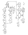
- an acoustic-electrical converter 1 receives acoustic signals and converts them into electrical signals.
- the acoustic signals result from one or more hand clapping or whistling or the like.
- the first branch consists of a selective amplifier 3 with a bandwidth b 11 11 kHz and a pass frequency in the range from 10 Hz to 12 kHz.
- the signals filtered out and amplified by the selective amplifier 3 are fed to a rectifier 4, the output of which is connected to a filter 5, which converts the rectified signals into a switching voltage A by integrating the pulses received by the amplifier 4.
- the second branch of the pulse shaper consists of a control amplifier 6, to which the output signals of the amplifier 2 are applied.
- the output of the control amplifier 6 is connected to a rectifier 7, followed by a filter 8, in which the amplified and rectified signals are integrated, so that a switching threshold voltage B results.
- a comparator 11 compares the output signals A and B of the two branches and changes its logical output state whenever one of the two values exceeds the other.
- the output signal C of the comparator 11 is supplied in the form of a pulse train C (t) to a programmable digital switching mechanism 12 for deciding whether one of a plurality of predefined control pulse trains is present.
- the programming of the digital switching mechanism 12 with regard to the parameters ⁇ , ⁇ , ⁇ can be specified using the program selector switch 13.
- a predetermined mother signal sequence c (t) REF is generated by a programming unit 14.
- the programmable digital switching mechanism 12 can consist of a commercially available microprocessor which stores the parameters received from the unit 13 or the unit 14. Here it is possible to specify corresponding parameters for several acoustic pulse trains and to use them for a comparison with the input pulse train c (t) .
- Fig. 1 shows that a relay 16 or the like via the output signal D of the switching mechanism 12 via an amplifier 15. is activated, which carries out the desired control. As will be described later, however, several devices or processes to be controlled can be provided which are connected to one of several outputs of the switching mechanism 12.
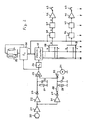
- Fig. 2 shows different units of Fig. 1 in greater detail.
- the electrical signals output by a converter 20 are amplified in an amplifier 21 of a known type and fed to the pulse shaper, which consists of the units 22 to 33 corresponding to the units 3 to 11 of FIG. 1.
- a specified pulse sequence is recognized via the units 34 to 39 and one or more units to be controlled are excited via the units 40 to 47. Examples of devices to be controlled are lamps, television and radio devices, air conditioning systems, motors, etc.
- the electrical signals amplified by the amplifier 21 are processed in the two parallel branches of the pulse shaper.
- the selective amplifier 22 corresponds to the selective amplifier 3 of FIG. 1 and it only amplifies that france spectrum which is mainly caused by intentionally generated acoustic pulses.
- the selective amplifier 22 follows the rectifier 23 and the filter consisting of an RC element 24, 25, which outputs the switching voltage A proportional to the amplitude of the respective acoustic pulse.
- a control amplifier 26 known per se, followed by rectifier 27 and a filter 30, which consists of a series resistor 28 and a parallel combination of a resistor 29 and a capacitor 30.
- a switching threshold voltage B proportional to the average noise level at the converter 20 is thus generated at the capacitor 30.
- a minimum switching threshold voltage B min for low noise levels is generated at the output of the capacitor 30 via the clamping circuit consisting of voltage source 31 and rectifier 32.
- the switching voltage A and the switching threshold voltage B are each applied to an input of a comparator 33, which compares the two voltage values A and B. For the condition A> B, the output signal of the comparator 33 changes from 0 to 1.
- This pulse rising edge triggers two monostable multivibrators 34 and 36.
- the monostable multivibrator 34 is activated for a predetermined time, for example 200 ms, and the falling edge of its output pulse is used as a switching signal for uses a counter 37, which consists of several counting stages.
- the monostable multivibrator 36 can be triggered again and its time constant can be set via the resistor and switch arrangement 35, which serves to preset the time interval ⁇ t i max . As long as the condition ⁇ is fulfilled, the monostable multivibrator 36 remains activated, so that the counter 37 is also ready to count the counting pulses applied by the monostable multivibrator 34.
- the monostable multivibrator 34 ensures that only defined pulses with a pulse interval longer than the time constant of the monostable multivibrator 34 are passed to the counter 37. Interference impulses and noise signals are thus suppressed. If the time constant of the monostable multivibrator 34 is made adjustable, even the minimum time interval between pulses of a predetermined sequence can be controlled in this way.
- the parameter ⁇ t i max is set to a constant value for all pulses of all pulse sequences by means of the resistor and switch arrangement 35.
- a microprocessor in the programmable, digital switching mechanism 12 of FIG. 1 it is possible to specify the maximum pulse interval ⁇ t i max differently for two successive pulses and for each pulse train.
- the Fi g. 2 ⁇ t n max according to condition ⁇ when using the resistor and switch arrangement - now g 35 ⁇ t i max according to Condition ⁇ .
- this parameter can also have a different value for each pulse sequence.
- the counter 37 is preferably a 1-out-of-k counter, the 1 bit being incremented by the input pulses from the monostable multivibrator 34 and activating one output of the counter after the other. Each output signal can then trigger a different control.
- the counter 37 can also be a binary decimal counter, the outputs of which are decoded by means of a decoding device in order to activate a corresponding process.
- Slide switches 38, 39 serve to selectively connect one or more counter outputs to a device to be controlled.
- the switch 38 has a wiper which is connected to the counter output k, the output of the switch 38 applying an output signal G to the D flip-flop 40.
- the other input of the flip-flop 40 is connected to the output of the monostable multivibrator 36. Whenever the output signal of this monostable multivibrator 36 takes a low value, the input information G is stored in the flip-flop 40. If the output of flip-flop 40 assumes a high value (H), flip-flop 41 changes its logic output state. When the output signal D of the flip-flop 41 is high, a relay 43 is excited via an amplifier 42. In this way, the desired switching operation is achieved.
- the switch 39 is connected with its terminal 1 to the counter output 1. Whenever this output is energized, a high value signal is transmitted via flip-flo ps 44 and 45 and amplifier 46 to relay 47 to energize it, relay 47 making another device effective.
- the counter reading is determined as the final counter reading only when the monostable multivibrator 36 is deactivated and becomes effective for a switching operation.
- the switches 38, 39 can also be replaced by a microprocessor control.
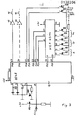
- FIG. 3 shows the implementation of the switching mechanism 12 by a microprocessor, for example the 8048 microprocessor from Intel, and the configuration of the input unit 14.
- the microprocessor 12 receives the input pulse sequence c (t) at its connection K39 (cf. FIG. 1). By pressing a button 100, the microprocessor 12 'can be reset via the input terminal K4.
- a clock generator is connected to the input terminals K2, K3, while the input terminal K7 is connected to ground.
- the Mikropro is connected to the input terminals K26 and K40 processor 12 'connected to a positive voltage source and grounded via the input terminal K20.
- Various devices to be controlled are connected to one or more connections via amplifiers 15, 15 'and relays 16, 16'. 3 shows the connections P10 and P17 as an example.
- the decoding and control unit 14 ' which can be designed as a module HEF 4514, is used to enter the parameters alpha, beta, gamma. As illustrated in FIG. 3, the parameters alpha, beta, gamma are entered via keys 101 to 106 into the decoding and control unit 14 ', which applies the corresponding signals to the connections P22, P23 and P24 of the microprocessor 12' which decodes - and control unit 14 'controls the connections P25, P26.
- the program After resetting the microprocessor, the program is started and the processor is put on hold.
- pulse sequences c (t) are entered, the microprocessor continuously checks them for agreement with one of the reference pulse sequences or with the stored parameters. If a match is found, the connection P10 or P17 etc. assigned to the detected pulse sequence assumes a high voltage value and the assigned device is excited via the amplifier 15, 15 'and the relay 16, 16'.
- the assigned connection P10 or P17 is reset to 0 and the switching process is canceled.
- the switching conditions Alpha, Beta and Gamma can be changed via the input keyboard 101 to 106.
- the microprocessor 12 * is informed via the connection P21 that the parameters alpha, beta, gamma are to be changed next, in particular the input of a reference pulse sequence c (t ref), the values alpha and beta of which are to be stored .
- the microprocessor 12 ' is informed via the connection P20 that the programming has been completed and at the same time the condition gamma is entered.
- the input of the reference pulse sequence can take place either via the converter 1, 20 (Fig. 1, Fig. 2) or by pressing the button 109 in pulses via the input terminal K39 to the microprocessor 12 '.
- connection z. B. P10 one device is controlled
- the signals of a plurality of connections can be fed to a decoding device in a modified embodiment, which then excites the corresponding device to be controlled.
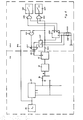
- FIG. 4 shows the switching mechanism 12 of the arrangement of FIG. 1 with corresponding structural units 34, 36, 37, 40 and 41 of FIG. 2. which are used to recognize a specific pulse sequence and to activate the device to be controlled selected therewith.
- the light intensity of a lamp 220 is to be controlled via an actuator 213, which is usually referred to as a dimmer and which, as is known, has a triac stage which receives its control signal from the control unit 212, which, for example, is the S 566 module from the company Siemens AG can be.
- the function of this control unit 212 is such that it is controlled by the .
- the leading edge of an input pulse is activated at input 214 and applies a control signal to actuator 213, which gradually increases and decreases the luminosity of lamp 220, as can be seen in FIG. 6. If the input pulse at input 214 drops, the luminance just reached is maintained. If a pulse of short duration, for example between 60 and 400 ms, preferably 200 ms, is applied to input 214, lamp 220 is switched off.
- the output signal of the monostable multivibrator 34 (FIG. 2) is present via line 203.
- the outputs of the AND gates 209 and 210 are combined via an OR gate, the output of which is connected to the input 214 of the control unit 212.
- a signal G is generated at the output of the switching device 36 for the first time when, according to FIG. 6, first line 3 pulses have been generated with the same predetermined distance, as explained in detail in the main patent.
- the two flip-flops 40, 4l produce a 1 signal on line 204, which switches the flip-flop 207 so that its Q output assumes the value 1 and a 1 signal to the input via the AND gate 209 214 of the control unit 212 is created. This signal is retained until a pulse occurs again at the monostable multivibrator 34, ie until a single hand clapping has taken place.
- the AND gate 206 is switched through via line 203 and resets the flip-flop 41 via line 202, so that a zero signal occurs on line 204, via which the flip-flop 207 switches and the AND gate 206 and 209 are blocked. Since the Q output of the flip-flop 207 is at 1, the AND gate 210 is prepared and then switched through for the duration t 3 when a signal G is generated again after clapping hands three times and is applied to the monostable multivibrator 208 (cf. Fig. 6). The short pulse applied via the AND gate 210 and the OR gate 211 to the input 214 of the control unit 212 switches off the illumination of the lamp 220.
- the luminosity change is ended by clapping hands once and a single pulse on line 203
- this switching process can also be achieved in another way by applying a corresponding control signal to line 203, which is derived, for example, from an output of counter 37. It thus shows that not only a switching operation can be triggered with the circuit arrangement according to the invention, but also continuous control can be carried out.
- the control unit 212 can also be influenced manually by means of a key 215.
- any other current- or voltage-dependent device such as a fan, a pump or the like, can also be controlled with the circuit arrangement according to the invention, possibly with modification.
- FIG. 5 illustrates a circuit arrangement according to a further exemplary embodiment of the invention, in which the direction and extent of an adjustment by means of an electric motor is to be controlled via a switching mechanism 201.
- Application examples are roller shutters, valves or the like.
- the function of the switching mechanism 201 is similar to that of the embodiment in FIG. 4; it is explained below with reference to FIG. 7.
- the time constant t 4 of the monostable multivibrator 228 is dimensioned such that a pulse is generated which is sufficient to reset the flip-flop 41, which occurs each time one of the limit switches 228 or 229 is closed.
- the two exemplary embodiments show that a wide variety of processes can be controlled if necessary with modification.
- An evaluable pulse sequence c (t) can also be derived according to the invention from a spoken word or sentence or other sound sequences produced by humans, so that control of processes and devices is also possible by means of commands given by humans, if such Command as reference pulse follow c (t) REF in the arrangement beforehand was given.
- the selective amplifier 3 is preferably connected in parallel with further selective amplifiers with suitably selected other pass frequencies.
- the pulse train c (t) generated is then evaluated in the manner already described.
- An additional distinction could be achieved in that when the respective selective amplifier is activated, a reference signal is derived which, in temporal association with the pulse generated by the selective amplifier, represents additional information in the pulse train which is evaluated upon detection, for example, by further AND operations can be.
Landscapes
- Physics & Mathematics (AREA)
- General Physics & Mathematics (AREA)
- Measurement Of Mechanical Vibrations Or Ultrasonic Waves (AREA)
- Investigating Or Analyzing Materials By The Use Of Ultrasonic Waves (AREA)
- Measuring Pulse, Heart Rate, Blood Pressure Or Blood Flow (AREA)
Applications Claiming Priority (4)
| Application Number | Priority Date | Filing Date | Title |
|---|---|---|---|
| DE19833337159 DE3337159A1 (de) | 1983-10-12 | 1983-10-12 | Anordnung zur ausloesung von elektrischen schaltvorgaengen |
| DE3337159 | 1983-10-12 | ||
| DE19843431708 DE3431708A1 (de) | 1984-08-29 | 1984-08-29 | Schaltungsanordnung zur durchfuehrung von steuervorgaengen |
| DE3431708 | 1984-08-29 |
Publications (2)
| Publication Number | Publication Date |
|---|---|
| EP0138206A2 true EP0138206A2 (fr) | 1985-04-24 |
| EP0138206A3 EP0138206A3 (fr) | 1987-05-13 |
Family
ID=25814803
Family Applications (1)
| Application Number | Title | Priority Date | Filing Date |
|---|---|---|---|
| EP84112258A Withdrawn EP0138206A3 (fr) | 1983-10-12 | 1984-10-12 | Dispositif pour la commande d'appareils et d'événements |
Country Status (1)
| Country | Link |
|---|---|
| EP (1) | EP0138206A3 (fr) |
Cited By (3)
| Publication number | Priority date | Publication date | Assignee | Title |
|---|---|---|---|---|
| EP0203913A4 (fr) * | 1984-01-13 | 1989-02-06 | Sentron Ltd | Appareil de regulation. |
| DE4324497A1 (de) * | 1992-07-23 | 1994-04-21 | Roman Koller | Verfahren und Anordnung zur ferngewirkten Schaltung eines Verbrauchers |
| US6561672B2 (en) | 2001-08-31 | 2003-05-13 | Lloyd E. Lessard | Illuminated holder |
Family Cites Families (4)
| Publication number | Priority date | Publication date | Assignee | Title |
|---|---|---|---|---|
| DE1919972A1 (de) * | 1969-04-19 | 1970-11-19 | Sonus Corp | Vorrichtung zur Fernsteuerung eines Geraets |
| DE2540228A1 (de) * | 1975-09-10 | 1977-03-24 | Gerard Kuffer | Fernbedienbarer elektronischer schalter |
| DE2935821A1 (de) * | 1979-09-05 | 1981-03-26 | Dynamit Nobel Ag, 5210 Troisdorf | Verfahren zur informationsuebertragung auf wirkkoerper, insbesondere minen, nach deren verlegung |
| JPS5644255A (en) * | 1979-09-20 | 1981-04-23 | Matsushita Electric Ind Co Ltd | Sound switch |
-
1984
- 1984-10-12 EP EP84112258A patent/EP0138206A3/fr not_active Withdrawn
Cited By (3)
| Publication number | Priority date | Publication date | Assignee | Title |
|---|---|---|---|---|
| EP0203913A4 (fr) * | 1984-01-13 | 1989-02-06 | Sentron Ltd | Appareil de regulation. |
| DE4324497A1 (de) * | 1992-07-23 | 1994-04-21 | Roman Koller | Verfahren und Anordnung zur ferngewirkten Schaltung eines Verbrauchers |
| US6561672B2 (en) | 2001-08-31 | 2003-05-13 | Lloyd E. Lessard | Illuminated holder |
Also Published As
| Publication number | Publication date |
|---|---|
| EP0138206A3 (fr) | 1987-05-13 |
Similar Documents
| Publication | Publication Date | Title |
|---|---|---|
| DE69425247T2 (de) | Fernbedienungsteuerungssystem, beleuchtungssystem und filter | |
| EP0168895B1 (fr) | Dispositif d'aide auditive | |
| DE3235279C2 (de) | Spracherkennungseinrichtung | |
| DE2906696C2 (fr) | ||
| DE2747733A1 (de) | Digitale elektronische steuerschaltung | |
| DE19611026C2 (de) | Klirrunterdrückung bei Hörgeräten mit AGC | |
| DE2305847B2 (de) | Anordnung zum erzeugen einer beliebigen frequenz aus einer anzahl in einem breiten frequenzband liegender diskreter frequenzen | |
| DE69528934T2 (de) | FM-Empfänger | |
| DE2653802A1 (de) | Fernsteuersystem | |
| EP1802169A2 (fr) | Méthode pour commander un appareil auditif en fonction d'une durée de déconnexion et appareil auditif correspondant | |
| EP0138206A2 (fr) | Dispositif pour la commande d'appareils et d'événements | |
| EP0931384A1 (fr) | Systeme de transmission de donnees | |
| CH638936A5 (de) | Verfahren und schaltungsanordnung zur ueberwachung eines funkempfaengers. | |
| DE2919228C2 (de) | Akustisch fernbedienbarer Schalter | |
| DE2749559A1 (de) | Fernsteuereinrichtung | |
| DE2643912C2 (de) | Schaltungsanordnung zum Auslösen von Schaltvorgängen durch akustische Signale | |
| DE3403836C2 (fr) | ||
| DE2707610C3 (de) | Schaltungsanordnung zur Auswertung einer digitalen Impulsfolge mit einem Vorimpuls | |
| DE3340775C2 (de) | Schaltungsanordnung zum Empfang von Infrarotlicht-Signalen | |
| DE3431708A1 (de) | Schaltungsanordnung zur durchfuehrung von steuervorgaengen | |
| DE102010040689A1 (de) | Audiosystem und Verfahren zum Durchführen eines Audioquellenwechsels | |
| DE10134813B4 (de) | Steuerung mit einer Steuereinrichtung zum Steuern/Regeln wenigstens des Stellweges eines fremdkraftbetätigten Stellantriebes eines Kraftfahrzeuges, insbesondere zum Verstellen eines Fensterhebers oder Schiebedachs | |
| DE4014394C2 (fr) | ||
| DE2752657A1 (de) | Stoergeraeuschabhaengige lautstaerkensteuerung | |
| DE2111590A1 (de) | System zum Einblenden von Durchsagen in ein laufendes Programm |
Legal Events
| Date | Code | Title | Description |
|---|---|---|---|
| PUAI | Public reference made under article 153(3) epc to a published international application that has entered the european phase |
Free format text: ORIGINAL CODE: 0009012 |
|
| AK | Designated contracting states |
Designated state(s): AT BE CH DE FR GB IT LI NL SE |
|
| RTI1 | Title (correction) | ||
| PUAL | Search report despatched |
Free format text: ORIGINAL CODE: 0009013 |
|
| AK | Designated contracting states |
Kind code of ref document: A3 Designated state(s): AT BE CH DE FR GB IT LI NL SE |
|
| STAA | Information on the status of an ep patent application or granted ep patent |
Free format text: STATUS: THE APPLICATION IS DEEMED TO BE WITHDRAWN |
|
| 18D | Application deemed to be withdrawn |
Effective date: 19871116 |