EP0138315A1 - Appareil de chauffage d'un joint et alimentation de carburant utilisant un tel appareil - Google Patents
Appareil de chauffage d'un joint et alimentation de carburant utilisant un tel appareil Download PDFInfo
- Publication number
- EP0138315A1 EP0138315A1 EP84305331A EP84305331A EP0138315A1 EP 0138315 A1 EP0138315 A1 EP 0138315A1 EP 84305331 A EP84305331 A EP 84305331A EP 84305331 A EP84305331 A EP 84305331A EP 0138315 A1 EP0138315 A1 EP 0138315A1
- Authority
- EP
- European Patent Office
- Prior art keywords
- throttle body
- heater
- engine
- opening
- gasket
- Prior art date
- Legal status (The legal status is an assumption and is not a legal conclusion. Google has not performed a legal analysis and makes no representation as to the accuracy of the status listed.)
- Granted
Links
- 239000000446 fuel Substances 0.000 title claims abstract description 54
- 230000013011 mating Effects 0.000 claims abstract description 15
- 238000002485 combustion reaction Methods 0.000 claims abstract description 7
- 125000006850 spacer group Chemical group 0.000 claims description 44
- 239000000203 mixture Substances 0.000 claims description 16
- 239000000463 material Substances 0.000 claims description 13
- 238000007789 sealing Methods 0.000 claims description 11
- 229910052751 metal Inorganic materials 0.000 claims description 5
- 239000002184 metal Substances 0.000 claims description 5
- 238000004891 communication Methods 0.000 claims description 4
- 238000001704 evaporation Methods 0.000 claims description 4
- 230000008020 evaporation Effects 0.000 claims description 3
- 239000012530 fluid Substances 0.000 claims description 3
- 239000011810 insulating material Substances 0.000 claims description 3
- 239000007769 metal material Substances 0.000 claims description 3
- ISWSIDIOOBJBQZ-UHFFFAOYSA-N phenol group Chemical group C1(=CC=CC=C1)O ISWSIDIOOBJBQZ-UHFFFAOYSA-N 0.000 claims description 3
- 238000010438 heat treatment Methods 0.000 claims description 2
- 229910052782 aluminium Inorganic materials 0.000 description 4
- XAGFODPZIPBFFR-UHFFFAOYSA-N aluminium Chemical compound [Al] XAGFODPZIPBFFR-UHFFFAOYSA-N 0.000 description 4
- 238000002347 injection Methods 0.000 description 4
- 239000007924 injection Substances 0.000 description 4
- 239000000853 adhesive Substances 0.000 description 3
- 230000001070 adhesive effect Effects 0.000 description 3
- RYGMFSIKBFXOCR-UHFFFAOYSA-N Copper Chemical compound [Cu] RYGMFSIKBFXOCR-UHFFFAOYSA-N 0.000 description 2
- 239000010425 asbestos Substances 0.000 description 2
- 229910010293 ceramic material Inorganic materials 0.000 description 2
- 238000001816 cooling Methods 0.000 description 2
- 229910052802 copper Inorganic materials 0.000 description 2
- 239000010949 copper Substances 0.000 description 2
- 238000010304 firing Methods 0.000 description 2
- 230000000977 initiatory effect Effects 0.000 description 2
- 230000001105 regulatory effect Effects 0.000 description 2
- 229910052895 riebeckite Inorganic materials 0.000 description 2
- 241000239290 Araneae Species 0.000 description 1
- 230000002547 anomalous effect Effects 0.000 description 1
- JRPBQTZRNDNNOP-UHFFFAOYSA-N barium titanate Chemical compound [Ba+2].[Ba+2].[O-][Ti]([O-])([O-])[O-] JRPBQTZRNDNNOP-UHFFFAOYSA-N 0.000 description 1
- 229910002113 barium titanate Inorganic materials 0.000 description 1
- 230000036760 body temperature Effects 0.000 description 1
- 239000004020 conductor Substances 0.000 description 1
- 230000000694 effects Effects 0.000 description 1
- 239000012777 electrically insulating material Substances 0.000 description 1
- 229920006332 epoxy adhesive Polymers 0.000 description 1
- 239000000945 filler Substances 0.000 description 1
- 238000012986 modification Methods 0.000 description 1
- 230000004048 modification Effects 0.000 description 1
- -1 nitrile compound Chemical class 0.000 description 1
- 150000002825 nitriles Chemical class 0.000 description 1
- 230000000087 stabilizing effect Effects 0.000 description 1
Images
Classifications
-
- F—MECHANICAL ENGINEERING; LIGHTING; HEATING; WEAPONS; BLASTING
- F02—COMBUSTION ENGINES; HOT-GAS OR COMBUSTION-PRODUCT ENGINE PLANTS
- F02M—SUPPLYING COMBUSTION ENGINES IN GENERAL WITH COMBUSTIBLE MIXTURES OR CONSTITUENTS THEREOF
- F02M31/00—Apparatus for thermally treating combustion-air, fuel, or fuel-air mixture
- F02M31/02—Apparatus for thermally treating combustion-air, fuel, or fuel-air mixture for heating
- F02M31/12—Apparatus for thermally treating combustion-air, fuel, or fuel-air mixture for heating electrically
- F02M31/135—Fuel-air mixture
-
- H—ELECTRICITY
- H05—ELECTRIC TECHNIQUES NOT OTHERWISE PROVIDED FOR
- H05B—ELECTRIC HEATING; ELECTRIC LIGHT SOURCES NOT OTHERWISE PROVIDED FOR; CIRCUIT ARRANGEMENTS FOR ELECTRIC LIGHT SOURCES, IN GENERAL
- H05B3/00—Ohmic-resistance heating
- H05B3/10—Heating elements characterised by the composition or nature of the materials or by the arrangement of the conductor
- H05B3/12—Heating elements characterised by the composition or nature of the materials or by the arrangement of the conductor characterised by the composition or nature of the conductive material
- H05B3/14—Heating elements characterised by the composition or nature of the materials or by the arrangement of the conductor characterised by the composition or nature of the conductive material the material being non-metallic
- H05B3/141—Conductive ceramics, e.g. metal oxides, metal carbides, barium titanate, ferrites, zirconia, vitrous compounds
-
- Y—GENERAL TAGGING OF NEW TECHNOLOGICAL DEVELOPMENTS; GENERAL TAGGING OF CROSS-SECTIONAL TECHNOLOGIES SPANNING OVER SEVERAL SECTIONS OF THE IPC; TECHNICAL SUBJECTS COVERED BY FORMER USPC CROSS-REFERENCE ART COLLECTIONS [XRACs] AND DIGESTS
- Y02—TECHNOLOGIES OR APPLICATIONS FOR MITIGATION OR ADAPTATION AGAINST CLIMATE CHANGE
- Y02T—CLIMATE CHANGE MITIGATION TECHNOLOGIES RELATED TO TRANSPORTATION
- Y02T10/00—Road transport of goods or passengers
- Y02T10/10—Internal combustion engine [ICE] based vehicles
- Y02T10/12—Improving ICE efficiencies
Definitions
- the field of this invention is that of fuel systems for furnishing an air-fuel mixture to an internal combustion engine, and the invention relates more particularly to means for preventing freeze-up of a fuel supply or inlet means such as, idle screw or nozzle means or the like in a throttle body used in such a system during operation of the system.
- idling speed fuel supply or fuel inlet nozzle means or the like are arranged in a throttle body for furnishing a selected fine stream of fuel into a throttle body for evaporating the fuel to form an air-fuel mixture to be furnished to an engine during idling operation of the engine
- the cooling effect of expansion or evaporation of air and/or air-fuel mixtures in the throttle body means has a tendency to cause at least temporary freeze-up of such idle speed fuel inlet nozzle means with resulting failure of engine firing or loss of suitable engine driveability.
- Similar problems can also occur with freeze-up of air inlet nozzles or openings or the like in throttle bodies used in throttle body fuel injection systems or in direct port fuel injection systems and the like. Such freeze-ups tend to occur particularly during the occurrence of selected atmospheric conditions. It would be desirable if heat could be furnished to throttle bodies of such systems promptly after initiation of engine operation to prevent such freeze-ups.
- the novel and improved fuel supply system of this invention comprises throttle body means having passage means therein open at one end for communicating with a corresponding opening in an intake manifold of an internal combustion engine.
- the throttle body means has flange means which are disposed around the open end of the passage means to mate with corresponding flange means provided on the intake manifold around the manifold opening.
- Idle speed fuel supply or inlet nozzle means or the like are provided on the throttle body means at a selected location relative to the throttle body flange means for furnishing fuel to be evaporated within the .
- throttle body means to form an air-fuel mixture to be furnished to the engine through the passage means during idling operation of the engine.
- Gasket means are provided between the throttle body flange means and the mating engine flange means and electrical resistance means are accommodated at a location between portions of the throttle body and engine flange means in a selected disposition within the gasket means relative to the noted nozzle means to transfer heat to the throttle body flange means for preventing freeze-up of the nozzle means during operation of the fuel supply system.
- the gasket heater means has a low profile to be compactly accommodated between the throttle body flange means and the mating engine flange means, the gasket heater means preferably comprising a first spacer layer member of a relatively rigid electrically and thermally insulating material such as a phenolic material or the like of selected thickness.
- the spacer member has a first opening forming a chamber in the spacer and has a second opening which is aligned between the throttle body passage means and the intake manifold opening.
- a second heat-transfer layer member formed of a thermally and electrically conductive material such as aluminum or the like having an opening therein aligned with the passage means has one side secured in overlying substantially coextensive and preferably in sealing, relation to one side of the spacer member to extend over the spacer chamber.
- An electrically conductive terminal member is embedded in the spacer member, preferably flush with an outer surface of an opposite side of the spacer member, so that the terminal means extends into the spacer chamber and preferably seals the chamber.
- a self-regulating electrical resistance heater of a ceramic material or the like of positive temperature coefficient of resistivity has one side secured in thermally and electrically conductive relation to said one side of the heat-transfer member so that the heater is accommodated within and sealed in protected relation within the spacer chamber by the relatively rigid spacer material.
- Spring means are also accommodated in the chamber for electrically connecting an opposite side of the heater to said terminal means.
- Third and fourth gasket layer members of a relatively thin and compressible electrically insulating gasket material such as an asbestos-filled nitrile compound or the like have respective openings therein aligned with the throttle body passage means, the third and fourth members being secured in substantially coextensive, overlying relation to an opposite side of the heat-transfer member and to said opposite side of the spacer respectively in sealing engagement with respective throttle body flange means and the mating engine flange means.
- the noted terminal means has an end extending therefrom beyond a lateral edge of the spacer member for connecting one side of the heater in an electrical circuit.
- the third gasket layer member also preferably has an additional opening therein and additional resilient spring means are secured in electrically conductive relation to the heat-transfer member to extend through . said additional opening to electrically engage the throttle body flange means for connecting the other side of the heater in the electrical circuit.
- the heater is adapted to be energized promptly on initiation of operation of the engine to avoid freeze-up of the idle speed fuel inlet nozzle means or the like provided in the throttle body means as air or an air-fuel mixture is furnished to the engine through the throttle body.
- the gasket heater means is compact, reliable and inexpensive and is adapted to be easily and reliably accommodated between the throttle body means and the engine for providing improved engine operation.
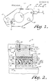
- Fig. 1 indicates the novel and improved gasket heater means of this invention which is shown in Fig. 2 to be incorporated in the novel and improved throttle body of the fuel system 12 of this invention.
- the system 12 includes a throttle body means 14 having passage means 16 open at one end 16.1 to communicate with a corresponding opening 18 at an intake manifold of an internal combustion engine diagrammatically indicated at 20 in Fig. 2.
- the throttle body means has flange means 22 arranged around the open passage end 16.1. for cooperating with corresponding or mating flange means 24 on the intake manifold and the gasket heater means 10 is arranged between the noted flange means for sealing communication between the passage means 16 and the intake manifold opening.
- screw means are extended through mounting holes 27 provided in the gasket means 10 and through corresponding mounting holes (not shown) in the throttle body flange means 22 and mating flange means 24 for mountina the throttle body on the engine in a conventional manner.
- Nozzle means 26 of any conventional type are provided in the throttle body means to open into the passage means 16.
- the nozzle means 26 comprises idle speed fuel supply or inlet means in a carburetion system of conventional type for furnishing fuel into the passage as is diagrammatically indicated at 28 in Fig. 2, thereby to form an air-fuel mixture in the throttle body means and to furnish that mixture to the engine as is indicated in Fig. 2 by the arrows 30 for regulating idling operation of the engine in conventional manner.
- nozzle means can comprise air inlet means or the like in a throttle body fuel injection or a direct port fuel injection system or the like within the scope of this invention.
- Throttle valve means 32 are movably mounted in the passage means for regulating the flow of the air-fuel mixture to the engine in conventional manner.
- the idle speed fuel inlet nozzle means 26 comprises a needle or valve member 26.1 threadedly engaged in the throttle body means as diagrammatically indicated at 26.2 in Fig. 2 so that a valve end 26.3 of the member is movable in a fuel entry passage 26.4 toward and away from a valve seat 26.5 formed in the fuel entry passage when head means or other valve controlled means 26.6 or the like are rotated as is indicated by arrow 26.7.
- the nozzle means 26 is of any conventional type in accordance with this invention, it is not further described herein and it will be understood that the nozzle means comprises a fluid inlet into the passage means 16 of the type such that cooling which results from expansion of air or evaporation of fuel in the throttle body would tend to cause at least temporary or intermittent freeze-up of the nozzle means 26 resulting in occasional failure of engine firing or loss of engine driveability under at least some atmospheric conditions.
- the novel and improved gasket heater means 10 are arranged between the throttle body flange means 22 and the mating engine flange 24 so that electrical resistance heater means accommodated in the gasket means are located between portions of the throttle body flange means and the mating engine flange means at a selected location relative to the nozzle means 26 for transferring heat to the throttle body flange means for heating the throttle body and nozzle means to prevent such freeze-up of the nozzle means.
- gasket means 10 comprises a first spacer layer member 34 formed of a relatively rigid, thermally and electrically insulating phenolic material or the like.
- the spacer member has a first opening which forms a chamber 36 in the spacer and has a second, typically larger opening 38 which is aligned with the passage means 16 and with the intake manifold opening 18 as shown in Fig. 2.
- the spacer member has a selected thickness providing the chamber 36 with a selected capacity as discussed below.
- a second, heat-transfer layer member 40 preferably formed of a metal material such as aluminum or the like of relatively high thermal and electrical conductivity has a corresponding opening 42 also aligned with the passage 16.
- the heat-transfer member has one side 40.1 which is secured in substantially coextensive, overlying relation to one side 34.1 of the spacer member.
- the heat-transfer member extends over the chamber 36 and is preferably sealed to the spacer 34 by an adhesive (not shown) or by fusing of the spacer material or the like for sealing one end of the chamber 36.
- An electrically conductive metal terminal means 44 is embedded in the heater means 10 to extend into the opposite end of the chamber 36.
- the terminal means comprises an element of aluminum or copper or the like which is embedded in a slot 34.2 in the spacer 34 so that one end 44.1 of the terminal extends into the chamber to cover said opposite end of the chamber, so that an opposite end 44.2 of the terminal extends out from a lateral edge of the spacer 34 for electrically connecting the terminal in an electrical circuit, and so that the terminal in the slot 34.2 is substantially flush with an outer surface 34.3 of the spacer, the slot preferably accommodating the terminal therein just slightly below the surface 34.3 for avoiding interference problems in subsequent assembly steps.
- the terminal is secured to the spacer by adhesive means of fusing of the spacer or the like so that the. terminal 44 seals the opposite end of the chamber.
- a self-regulating electrical resistance heater means 46 is accommodated in the chamber 36 to be energized therein for transferring heat to the throttle body flange means 22 through the heat-transfer member 40.
- the heater means comprises a heater unit having a body 46.1 of a ceramic material or the like such as lanthanum-doped barium titanate having a positive temperature coefficient of resistivity adapted to display a sharply anomalous increase in resistance at a selective, safe temperature level for stabilizing the heater at about that temperature.
- Ohmic contact layer'46.2, 46.3 of metal such as aluminum or the like are provided on opposite sides of the body 46.1 and one contact layer 46.2 at one side of the body is secured in electrically and thermally conducted relation to the heat-transfer member 40 so that the heater is accommodated in the chamber 36.
- the heater body is secured to the member 40 by use of an electrically and thermally conductive, metal- filled epoxy adhesive 46.4 or the like as shown in Fig. 2.
- Electrically conductive spring means 48 such as a spider spring formed of berrylium copper or the like are also accommodated in the chamber 36 between the opposite side of the heater body and the terminal 44 for electrically connecting the terminal to the heater.
- third and fourth gasket layer members 50 and 52 each having an opening 54, 56 therein aligned with the passage 16 are disposed on opposite outer sides of the gasket means 10 to sealingly engage the throttle body flange means 22 and the intake manifold flange 24 respectively.
- the third and fourth layer members are preferably relatively thinner and of relatively more compressible electrically insulating material than the spacer 34 and are preferably secured by fusing or adhesive means or the like at opposite sides of the gasket means 10 so that one gasket layer member 50 is disposed in substantially coextensive, overlying relation to the heat-transfer member 40 and the other gasket member 52 overlies and is coextensive with the opposite side 34.3 of the spacer without interference with the terminal 44 accommodated in the slot 34.2.
- an asbestos-filled nitrile gasket material is used but other compressible materials with or without other fillers are also used within the scope of this invention.
- the gasket layer 50 has an additional terminal opening 50.1 therein (see Fig.
- additional resilient terminal spring means such as a plurality of leaves 58 are secured to the side 40.2 of the heat-transfer member 40 at one end 58.1 so that opposite ends 58.2 of the springs extend through the opening 50.1 to electrically engage the throttle body or intake manifold flanges 22 and 24 thereby to connect the side 46.2 of the heater body to the throttle body flange in the noted electrical circuit as will be understood.
- the end 44.2 of the terminal means embedded in the spacer is adapted to be electrically connected to an automotive power source such as the battery 58 through switch means or the like such as the ignition switch 60 diagrammatically illustrated in Fig. 1.
- the heater means 46 is thereby connected in an electrical circuit between the terminal 44 and the throttle body 14, as is diagrammatically indicated in Fig. 1. Accordingly the heater means is promptly energized when the switch 48 is closed for promptly generating heat and transferring that heat to the throttle body flange means 22 through the heat-transfer member 40 in an efficient manner. In that way, the throttle body means receives heat for preventing freeze-up of the nozzle means 26.
- the heater means is also self-regulating to stabilize at a safe temperature.
- the novel and improved gasket means 10 has a very low profile and is compactly accommodated between the flange means 22 and 24 and is readily connected in an electrical circuit.
- the heater means is safely and reliably accommodated within chamber 36 in the relatively rigid spacer 34 so it is protected during use when clamped between the flanges 22 and 24 and is preferably sealed therein for long service life.
- a thermostat means 62 as diagrammatically illustrated in Fig. 1 is also accommodated in a corresponding chamber in the rigid spacer 34 or the like, preferably adjacent to the nozzle means 26, to be responsive to throttle body temperature to open the noted circuit on warm days or the like for energizing the heater means 46 only when said temperature is below a selected ambient or other temperature level.
Landscapes
- Engineering & Computer Science (AREA)
- Chemical & Material Sciences (AREA)
- Combustion & Propulsion (AREA)
- Mechanical Engineering (AREA)
- General Engineering & Computer Science (AREA)
- Ceramic Engineering (AREA)
- Gasket Seals (AREA)
- Control Of Throttle Valves Provided In The Intake System Or In The Exhaust System (AREA)
Applications Claiming Priority (4)
| Application Number | Priority Date | Filing Date | Title |
|---|---|---|---|
| US06/526,717 US4465053A (en) | 1983-08-26 | 1983-08-26 | Fuel system having low profile gasket heater |
| US526769 | 1983-08-26 | ||
| US06/526,769 US4463737A (en) | 1983-08-26 | 1983-08-26 | Fuel system having gasket heater |
| US526717 | 1983-08-26 |
Publications (2)
| Publication Number | Publication Date |
|---|---|
| EP0138315A1 true EP0138315A1 (fr) | 1985-04-24 |
| EP0138315B1 EP0138315B1 (fr) | 1988-10-19 |
Family
ID=27062190
Family Applications (1)
| Application Number | Title | Priority Date | Filing Date |
|---|---|---|---|
| EP84305331A Expired EP0138315B1 (fr) | 1983-08-26 | 1984-08-06 | Appareil de chauffage d'un joint et alimentation de carburant utilisant un tel appareil |
Country Status (2)
| Country | Link |
|---|---|
| EP (1) | EP0138315B1 (fr) |
| DE (1) | DE3474709D1 (fr) |
Citations (3)
| Publication number | Priority date | Publication date | Assignee | Title |
|---|---|---|---|---|
| US4377148A (en) * | 1980-01-07 | 1983-03-22 | Toyota Jidosha Kogyo Kabushiki Kaisha | Fuel mixture heating device of an internal combustion engine |
| US4389354A (en) * | 1980-12-01 | 1983-06-21 | Mikuni Kogyo Kabushiki Kaisha | Heater for deicing carburetors |
| US4406785A (en) * | 1981-12-24 | 1983-09-27 | Gte Products Corporation | Diesel fuel heater |
-
1984
- 1984-08-06 EP EP84305331A patent/EP0138315B1/fr not_active Expired
- 1984-08-06 DE DE8484305331T patent/DE3474709D1/de not_active Expired
Patent Citations (3)
| Publication number | Priority date | Publication date | Assignee | Title |
|---|---|---|---|---|
| US4377148A (en) * | 1980-01-07 | 1983-03-22 | Toyota Jidosha Kogyo Kabushiki Kaisha | Fuel mixture heating device of an internal combustion engine |
| US4389354A (en) * | 1980-12-01 | 1983-06-21 | Mikuni Kogyo Kabushiki Kaisha | Heater for deicing carburetors |
| US4406785A (en) * | 1981-12-24 | 1983-09-27 | Gte Products Corporation | Diesel fuel heater |
Non-Patent Citations (2)
| Title |
|---|
| PATENT ABSTRACTS OF JAPAN vol. 5, no. 189, 28th November 1981, page (M-99) (861); & JP-A-56-110550 (NIPPON JIDOSHA) 01-09-1981 * |
| PATENT ABSTRACTS OF JAPAN vol. 6, no. 146, 5th August 1982, page (M-147) (1024); & JP-A-5765848 (TOYOTA) 21-04-1982 * |
Also Published As
| Publication number | Publication date |
|---|---|
| EP0138315B1 (fr) | 1988-10-19 |
| DE3474709D1 (en) | 1988-11-24 |
Similar Documents
| Publication | Publication Date | Title |
|---|---|---|
| US3806854A (en) | Control for automotive choke | |
| US4108125A (en) | High efficiency early fuel evaporation carburetion system | |
| US4870249A (en) | Electric fuel heating device | |
| US5050569A (en) | Fuel injection system for an internal combustion engine and fuel heating device therefor | |
| US4419564A (en) | Self-regulating electric heater for use in an early fuel evaporation system | |
| US4327697A (en) | Heater for air-fuel mixture having heating element of positive temperature coefficient resistor | |
| US4361125A (en) | Fuel evaporator for internal combustion engine | |
| US5086747A (en) | Internal combustion engine with fuel heater | |
| US5209211A (en) | Throttle valve connection piece | |
| US4463737A (en) | Fuel system having gasket heater | |
| US4465053A (en) | Fuel system having low profile gasket heater | |
| US4593670A (en) | Fuel evaporator for internal combustion engine | |
| US3477238A (en) | Thermoelectric antipercolator device for the fuel system of an internal combustion engine | |
| JPS6240541B2 (fr) | ||
| US4717808A (en) | Carburetor deicer | |
| US4237077A (en) | Automatic choke system | |
| EP0138315A1 (fr) | Appareil de chauffage d'un joint et alimentation de carburant utilisant un tel appareil | |
| US5134986A (en) | Internal combustion engine with fuel heater | |
| US4467773A (en) | Fuel supply system with improved throttle body heater | |
| JPS6147975B2 (fr) | ||
| US4389354A (en) | Heater for deicing carburetors | |
| JP2509167B2 (ja) | パツキンヒ−タ装置 | |
| EP0051925B1 (fr) | Système d'alimentation en combustible à starter automatique | |
| JPS6332926Y2 (fr) | ||
| JPS6047861A (ja) | 内燃機関の吸気路加熱装置 |
Legal Events
| Date | Code | Title | Description |
|---|---|---|---|
| PUAI | Public reference made under article 153(3) epc to a published international application that has entered the european phase |
Free format text: ORIGINAL CODE: 0009012 |
|
| AK | Designated contracting states |
Designated state(s): DE FR GB IT NL SE |
|
| 17P | Request for examination filed |
Effective date: 19851004 |
|
| 17Q | First examination report despatched |
Effective date: 19860611 |
|
| R17C | First examination report despatched (corrected) |
Effective date: 19870305 |
|
| ITF | It: translation for a ep patent filed | ||
| GRAA | (expected) grant |
Free format text: ORIGINAL CODE: 0009210 |
|
| AK | Designated contracting states |
Kind code of ref document: B1 Designated state(s): DE FR GB IT NL SE |
|
| PG25 | Lapsed in a contracting state [announced via postgrant information from national office to epo] |
Ref country code: SE Effective date: 19881019 |
|
| REF | Corresponds to: |
Ref document number: 3474709 Country of ref document: DE Date of ref document: 19881124 |
|
| ET | Fr: translation filed | ||
| PLBE | No opposition filed within time limit |
Free format text: ORIGINAL CODE: 0009261 |
|
| STAA | Information on the status of an ep patent application or granted ep patent |
Free format text: STATUS: NO OPPOSITION FILED WITHIN TIME LIMIT |
|
| 26N | No opposition filed | ||
| ITTA | It: last paid annual fee | ||
| PGFP | Annual fee paid to national office [announced via postgrant information from national office to epo] |
Ref country code: NL Payment date: 19930831 Year of fee payment: 10 |
|
| PG25 | Lapsed in a contracting state [announced via postgrant information from national office to epo] |
Ref country code: NL Effective date: 19950301 |
|
| NLV4 | Nl: lapsed or anulled due to non-payment of the annual fee | ||
| PGFP | Annual fee paid to national office [announced via postgrant information from national office to epo] |
Ref country code: DE Payment date: 19981012 Year of fee payment: 15 |
|
| PG25 | Lapsed in a contracting state [announced via postgrant information from national office to epo] |
Ref country code: DE Free format text: LAPSE BECAUSE OF NON-PAYMENT OF DUE FEES Effective date: 20000601 |
|
| PGFP | Annual fee paid to national office [announced via postgrant information from national office to epo] |
Ref country code: GB Payment date: 20000802 Year of fee payment: 17 |
|
| PGFP | Annual fee paid to national office [announced via postgrant information from national office to epo] |
Ref country code: FR Payment date: 20000818 Year of fee payment: 17 |
|
| PG25 | Lapsed in a contracting state [announced via postgrant information from national office to epo] |
Ref country code: GB Free format text: LAPSE BECAUSE OF NON-PAYMENT OF DUE FEES Effective date: 20010806 |
|
| GBPC | Gb: european patent ceased through non-payment of renewal fee |
Effective date: 20010806 |
|
| PG25 | Lapsed in a contracting state [announced via postgrant information from national office to epo] |
Ref country code: FR Free format text: LAPSE BECAUSE OF NON-PAYMENT OF DUE FEES Effective date: 20020430 |
|
| REG | Reference to a national code |
Ref country code: FR Ref legal event code: ST |