EP0138318A2 - Système de douche commandé par gravité - Google Patents
Système de douche commandé par gravité Download PDFInfo
- Publication number
- EP0138318A2 EP0138318A2 EP84305398A EP84305398A EP0138318A2 EP 0138318 A2 EP0138318 A2 EP 0138318A2 EP 84305398 A EP84305398 A EP 84305398A EP 84305398 A EP84305398 A EP 84305398A EP 0138318 A2 EP0138318 A2 EP 0138318A2
- Authority
- EP
- European Patent Office
- Prior art keywords
- reservoir
- shower system
- shower
- water
- platform
- Prior art date
- Legal status (The legal status is an assumption and is not a legal conclusion. Google has not performed a legal analysis and makes no representation as to the accuracy of the status listed.)
- Withdrawn
Links
Images

Classifications
-
- A—HUMAN NECESSITIES
- A47—FURNITURE; DOMESTIC ARTICLES OR APPLIANCES; COFFEE MILLS; SPICE MILLS; SUCTION CLEANERS IN GENERAL
- A47K—SANITARY EQUIPMENT; ACCESSORIES THEREFOR, e.g. TOILET ACCESSORIES
- A47K3/00—Baths; Showers; Appurtenances therefor
- A47K3/28—Showers or bathing douches
- A47K3/288—Independent, movable shower units operated by weight, by hand or by footpumps
Definitions
- the shower unit is provided with a second, non-compressible, reservoir to replenish the main reservoir and allow a number of showers to be taken without the need to refill the system with water. It is preferred to spring bias the movable platform so that on removal of the weight therefrom,.the platform returns towards the starting position - preferably thereby drawing more water into the compressible reservoir from such a secondary reservoir.
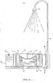
- FIG. 1 An embodiment of a shower system according to the invention is exemplified in Figures 1 and 2.
- compressible reservoir I is filled with shower water.
- the reservoir 1 is sealed by filler plug 2.
- the water is retained by deformable lining 3 confined by rigid reservoir side wall portions 4, 5.
- deformable lining 3 confined by rigid reservoir side wall portions 4, 5.
- Compression of reservoir 1 may be achieved by standing (or placing a massive object) on movable platform 6, which is attached to walls 4.
- Platform 6 is biased by springs 7 in such. a way that in its resting position the reservoir 1 is extended.
- a pipe 10 having a plurality of non-return valves 11 connects the reservoir 1 to a spray head 12.
- the system is primed before use by filling pipe 10 and spray head 12 with water using pump 13. Once the system is primed, a weight operating on platform 6 will cause
- This invention relates to a weight-operated shower system which utilises the downwardly acting force of a massive body, e.g. a shower user. Operation of the system is passive since no exertion is required to maintain water flow.
- the shower system of the present invention requires no external power source or pressurised water supply and is not driven by pressurised gas or stretched elasticated materials. It is simple and reliable in use, is inexpensive to manufacture and has the added advantage of being fully portable.
- the apparatus comprises essentially a compressible reservoir connected to a pipe and spray head.
- water is driven along the pipe and out of the spray head by the application of a downward force, e.g. the weight of a shower user, to a movable platform mounted over the compressible reservoir. Water is prevented from passing back into the reservoir by non-return valving in the pipe.
- the compressible reservoir should be defined or contained by structure which prevents the reservoir from expanding, e.g. if the reservoir comprises an elastic bag, it should be confined by an inelastic surround.
- a small priming pump for the pipe so that the pipe can be filled with water before the commencement of showering. a reduction in the confined volume of reservoir 1 and so will drive water out of spray head 12. Water will continue to flow so long as there is a weight on platform 6 and provided the reservoir has not reached the limit of its compressibility (i.e., maximum downward travel of platform 6).
- FIG. 2 the reservoir 1 is shown substantially fully compressed. Walls 4 and.5 overlap and the deformable lining 3 has crumpled. A volume of water equal to the change in confined volume of reservoir 1 has been driven out of the spray head 12.
- bias springs 7 return the reservoir to its original volume, thereby drawing water from secondary reservoir 15 past non-return valve 11 into the reservoir 1 to refill it.
- the pipe 10 and spray head 12 may be self supporting (e. g. , in the form of a telescopic tube) or may be designed to be attached to structure supplied as part of the system or.may be hand .held or may be supportable by a structure on site (e.g., a pole, tree, caravan or building).
- a structure on site e.g., a pole, tree, caravan or building.
- reservoir Whilst one particular shape and design of reservoir has been illustrated, other configurations may be used within the scope of the invention provided the reservoir is compressible and is confined by an inelastic surround. Similarly, whilst the system has been referred to as a. shower system, it could equally well be operated in other modes - e.g. without the spray head to produce a water stream.
- the platform and the shower base may each be provided with a tubular member, mutually slidable one into the other, upon which a coaxial biassing spring is mounted.
- An arrangement of a . plurality of such members around the platform perimiter may improve the stability of the platform when the shower is in use.
- the reservoir outlet may be placed above the lowest level of the reservoir so that, in use, some water is always retained in the reservoir when the platform has reached the point of maximum downward travel. This retained water mixes with refill water and thus acts as a safeguard against scalding if boiling water should be fed into the reservoir from the secondary reservoir.
- a filter may be included in the shower head to prevent blockage of the shower rose by solid objects in the shower water.
- a semi-rigid disc may be provided in the top of the reservoir lining, thereby holding the lining against the inner surface of the platform.
Landscapes
- Health & Medical Sciences (AREA)
- Public Health (AREA)
- Epidemiology (AREA)
- General Health & Medical Sciences (AREA)
- Nozzles (AREA)
Applications Claiming Priority (2)
| Application Number | Priority Date | Filing Date | Title |
|---|---|---|---|
| GB838321343A GB8321343D0 (en) | 1983-08-08 | 1983-08-08 | Weight-operated shower system |
| GB8321343 | 1983-08-08 |
Publications (2)
| Publication Number | Publication Date |
|---|---|
| EP0138318A2 true EP0138318A2 (fr) | 1985-04-24 |
| EP0138318A3 EP0138318A3 (fr) | 1985-07-10 |
Family
ID=10546992
Family Applications (1)
| Application Number | Title | Priority Date | Filing Date |
|---|---|---|---|
| EP84305398A Withdrawn EP0138318A3 (fr) | 1983-08-08 | 1984-08-08 | Système de douche commandé par gravité |
Country Status (2)
| Country | Link |
|---|---|
| EP (1) | EP0138318A3 (fr) |
| GB (1) | GB8321343D0 (fr) |
Cited By (3)
| Publication number | Priority date | Publication date | Assignee | Title |
|---|---|---|---|---|
| DE3816655A1 (de) * | 1988-05-17 | 1989-11-23 | Knoepfel Ingrid | Aufbaubare freizeit- und heimdusche |
| FR2706241A1 (fr) * | 1993-06-09 | 1994-12-23 | Boudault Patrick | Procédé de distribution d'eau à partir d'une réserve, notamment pour l'arrosage de plantes, réserve correspondante, et structure formant jardinière verticale mettant en Óoeuvre ce procédé. |
| CN112691972A (zh) * | 2020-12-15 | 2021-04-23 | 邹前明 | 一种检验科用器械表面快速清洗设备 |
Family Cites Families (4)
| Publication number | Priority date | Publication date | Assignee | Title |
|---|---|---|---|---|
| BE401343A (fr) * | ||||
| DE230197C (fr) * | ||||
| US3293664A (en) * | 1964-07-20 | 1966-12-27 | Coons Woodrow | Portable shower |
| US4064570A (en) * | 1976-04-26 | 1977-12-27 | Kim Sunyong P | Compact shower structure |
-
1983
- 1983-08-08 GB GB838321343A patent/GB8321343D0/en active Pending
-
1984
- 1984-08-08 EP EP84305398A patent/EP0138318A3/fr not_active Withdrawn
Cited By (3)
| Publication number | Priority date | Publication date | Assignee | Title |
|---|---|---|---|---|
| DE3816655A1 (de) * | 1988-05-17 | 1989-11-23 | Knoepfel Ingrid | Aufbaubare freizeit- und heimdusche |
| FR2706241A1 (fr) * | 1993-06-09 | 1994-12-23 | Boudault Patrick | Procédé de distribution d'eau à partir d'une réserve, notamment pour l'arrosage de plantes, réserve correspondante, et structure formant jardinière verticale mettant en Óoeuvre ce procédé. |
| CN112691972A (zh) * | 2020-12-15 | 2021-04-23 | 邹前明 | 一种检验科用器械表面快速清洗设备 |
Also Published As
| Publication number | Publication date |
|---|---|
| EP0138318A3 (fr) | 1985-07-10 |
| GB8321343D0 (en) | 1983-09-07 |
Similar Documents
| Publication | Publication Date | Title |
|---|---|---|
| US5087037A (en) | Pneumatically elevating recreational exercise device | |
| AU2008240589B2 (en) | A stabilising device | |
| US4787560A (en) | Portable liquid sprayer | |
| US2368091A (en) | Pump | |
| US3904326A (en) | Multi-purpose pump | |
| EP0138318A2 (fr) | Système de douche commandé par gravité | |
| US2923947A (en) | weighill | |
| US4972977A (en) | Spray bottle apparatus with pressure multiplying pistons | |
| WO2002058831A3 (en) | Apparatus for creating vortex rings | |
| US3816028A (en) | Pumps and painting installations | |
| US20070039768A1 (en) | Balance system by fluid transfer for legged robots | |
| US4384675A (en) | Gaseous fluid pump and liquid spray apparatus incorporating such a pump | |
| JPS6198979A (ja) | ポンプ装置 | |
| US3601315A (en) | Pocket supportable atomizer device | |
| JPS56113059A (en) | Storage device of wave energy | |
| CA2092759A1 (fr) | Pistolet a eau alimente a distance et servant de jouet | |
| CN219723312U (zh) | 一种防止药液振荡的背负式喷雾器 | |
| JP3429796B2 (ja) | ムースディスペンサ | |
| RU93055208A (ru) | Глубинный штанговый насос | |
| ES2127677A1 (es) | Bomba alternativa vertical. | |
| WO1997038795A1 (fr) | Pulverisateur a main pouvant etre mis sous pression | |
| KR900010535Y1 (ko) | 자동차 세척용 펌프 | |
| JPS5811396Y2 (ja) | 電動噴霧器 | |
| JPS54102609A (en) | Anti-seismic structure for spherical tank | |
| GB1049647A (en) | Apparatus for spraying liquids |
Legal Events
| Date | Code | Title | Description |
|---|---|---|---|
| PUAI | Public reference made under article 153(3) epc to a published international application that has entered the european phase |
Free format text: ORIGINAL CODE: 0009012 |
|
| AK | Designated contracting states |
Designated state(s): AT BE CH DE FR GB IT LI LU NL SE |
|
| PUAL | Search report despatched |
Free format text: ORIGINAL CODE: 0009013 |
|
| AK | Designated contracting states |
Designated state(s): AT BE CH DE FR GB IT LI LU NL SE |
|
| 17P | Request for examination filed |
Effective date: 19860224 |
|
| 17Q | First examination report despatched |
Effective date: 19870127 |
|
| STAA | Information on the status of an ep patent application or granted ep patent |
Free format text: STATUS: THE APPLICATION IS DEEMED TO BE WITHDRAWN |
|
| 18D | Application deemed to be withdrawn |
Effective date: 19880301 |
|
| RIN1 | Information on inventor provided before grant (corrected) |
Inventor name: THATCHER, IRVINE LAWRENCE |