EP0138352A2 - Verfahren zum Betrieb einer Datenverarbeitungsanlage über "Depictor" verbundene Mikrobefehle und logische Schaltungen - Google Patents
Verfahren zum Betrieb einer Datenverarbeitungsanlage über "Depictor" verbundene Mikrobefehle und logische Schaltungen Download PDFInfo
- Publication number
- EP0138352A2 EP0138352A2 EP84305968A EP84305968A EP0138352A2 EP 0138352 A2 EP0138352 A2 EP 0138352A2 EP 84305968 A EP84305968 A EP 84305968A EP 84305968 A EP84305968 A EP 84305968A EP 0138352 A2 EP0138352 A2 EP 0138352A2
- Authority
- EP
- European Patent Office
- Prior art keywords
- depictor
- activity
- type
- instruction
- program
- Prior art date
- Legal status (The legal status is an assumption and is not a legal conclusion. Google has not performed a legal analysis and makes no representation as to the accuracy of the status listed.)
- Granted
Links
Images


Classifications
-
- G—PHYSICS
- G06—COMPUTING OR CALCULATING; COUNTING
- G06F—ELECTRIC DIGITAL DATA PROCESSING
- G06F9/00—Arrangements for program control, e.g. control units
- G06F9/06—Arrangements for program control, e.g. control units using stored programs, i.e. using an internal store of processing equipment to receive or retain programs
- G06F9/44—Arrangements for executing specific programs
- G06F9/448—Execution paradigms, e.g. implementations of programming paradigms
- G06F9/4482—Procedural
- G06F9/4484—Executing subprograms
- G06F9/4486—Formation of subprogram jump address
Definitions
- This invention relates to data processing systems; and in particular, it relates to methods of operating such systems.
- a data processing system is operated by providing a program which consists of a sequence of instructions of some predetermined language. These instructions are executed one at a tine; and the particular instruction that is currently being executed is pointed to by a program counter.
- the program counter is incremented to point to the next sequential instruction unless the completed instruction was a JUMP instruction or a CALL instruction.
- the program counter is loaded with a new address as the JUMP instruction directs; and then instructions are sequentially executed beginning at that new address.
- a CALL instruction an independent procedure is executed and then control passes back to the instruction which follows the CALL instruction.
- a procedure is a separate special purpose sequence of instruction from the same predetermined language of which the program that called it is made up. From the point of view of the calling program, a procedure can be regarded as a single new higher level instruction even though it may be quite complicated and made up of hundreds of instructions from the predetermined language.
- Still another problem with the prior art method of operating a data processing system by means of CALL instructions and corresponding procedures is that the operation is too inflexible.
- the operation is too confined to include special purpose microcode routines or special purpose hardware logic units that perform procedure-like functions.
- a primary object of the invention' is to provide an improved method of operating a data processing system.
- Another object of the invention is to provide a method of enhancing the speed at which a data processing system operates.
- Still another object of the invention is to provide a method of operating a data processing system wherein procedure-like functions are performed by low level language microcode routines and hardware logic units.
- the activating step of the non-software mechanism can include the substep of executing a microcode program to perform the second activity; or alternatively, it includes the substep of sending parameters to a hardware logic unit to perform the second activity.
- the depictor in the above-recited method is a partitioned register in which one portion contains the name of the activity that is to be performed; another portion indicates whether the named activity is implemented via a procedure, a microcode routine, or a hardware logic unit; and another portion indicates how the named activity can be accessed.
- FIG. 1 a data processing system and method of operating the system in accordance with the invention will be described. Included in the Figure 1 system is a digital computer 10 which is coupled to a memory 11 via a bus 12. A software program 13 which computer 10 executes is stored in memory 11.
- the term "software program” means a sequence of high level language (HLL) instructions with each such instruction being interpreted by a microcode program of low level language (LLL) instructions.
- the low level language instructions are executed directly by digital logic circuitry in computer 10.
- Individual high level language instructions in software program 13 are indicated by reference numeral 14; and the low level language microcode programs are indicated by reference numeral 15 in a memory 16.
- CALL instructions 14a, 14b, and 14c Three of the illustrated high level language instructions 14 are CALL instructions 14a, 14b, and 14c which have been modified to operate in accordance with the present invention.
- This modified CALL instruction identifies an activity by name, discontinues the execution of the HLL software program of which it is a part, saves sufficient information to resume execution of the discontinued program at a later time at the point of discontinuance, and initiates the execution of the named activity by passing parameters and control to it.
- CALL instruction 14a identifies an activity A x to which control is to be passed along with parameters j and k.
- CALL instruction 14b identifies an activity Ay to which control is to be passed along with a parameter 1.
- CALL instruction 14c identifies another activity A z to which control is to be passed along with parameters m, n, and o.
- Each of the activities A x , Ay, and A z is either a special purpose software program (i.e., a procedure), a special purpose microcode program, or a special purpose hardware logic unit.
- the activity is adapted to receive parameters from the CALL instruction, operate on the received parameters in a predetermined fashion, and indicate to the CALL instruction that the operation is complete. For example, one activity may receive the names of several records as parameters from the CALL instruction, read the identified records from various storage units, and sort them in a predetermined order.
- activity A x is indicated by reference numeral 20 as being a special purpose procedure of HLL instructions in memory 11. Those high level language instructions are from the same language as the instructions which make up program 13. To execute activity A x , the address of the beginning high level language instruction in activity A x is loaded into a program counter in computer 10; and then instructions from activity A x are read via the high level language bus 12 into computer 10 where they are interpreted by the microcode programs 15.
- activity Ay is indicated by reference numeral 21 in Figure 1 as being a special purpose microcode program in memory 16.
- Microcode program 21 is made up of a sequence of low level language instructions which are read over a low level language bus 22 into computer 10 where they are executed directly by the computer's digital logic circuitry.
- activity A z is comprised of a special purpose logic unit which is coupled via an I/O bus 24 to computer 10.
- computer 10 sends the parameters of the CALL instruction to unit 23 via bus 24 and then merely waits for unit 23 to return the results of the operation which the activity performs.
- a depictor array 25 is also coupled to the I/O bus 24; and it contains respective depictors for each activity that is called in program 13.
- the Figure 1 array contains three depictors 25-1, 25-2, and 25-3.
- a depictor is herein meant a mechanism which links a named activity to other information which describes how the named activity can be accessed.
- each depictor in array 27 is a content addressable hardware register that is partitioned into three parts, "a", "b”. and "c".
- Part "a” contains the name of the activity.
- Part "b” identifies whether the named activity is a software program in memory 11 or a microcode program in memory 16 or a hardware logic unit on I/O bus 24.
- part "c" specifies the memory address or bus address at which the activity can be accessed.
- the name of an activity is sent over bus 24 to array 25; that name is compared with part "a” of the depictors until a match occurs; and parts "b” and "c" of the matching depictor are sent to computer 10.
- depictor 25-1 shows that it is a depictor for activity A x ; part “b” shows that activity A x is implemented by HLL instructions in memory 11 as a procedure; and part “c” shows that the instructions begin at address 5000.
- depictor 25-2 shows that activity Ay is implemented by low level language instructions which begin at microcode address 200; and depictor 25-3 shows that activity A z is implemented by a hardware logic unit which is at I/O bus address 100.
- FIG. 2 illustrates a flow chart for the portion 15a of the microcode programs 15 which is executed when a CALL instruction in program 13 is encountered.
- the microcode 15a directs computer 10 to fetch the depictor that is linked to the called activity from depictor array 25. Thereafter, as indicated by boxes 31, 32, and 33, the microcode 15a directs computer 10 to examine field "b" of the fetched depictor to sense how the called activity is linked to an implementation mechanism.
- the microcode 15a directs computer 10 to save the present program counter and load the memory address of the called activity into the program counter. This address is contained in portion "c" of the depictor of the called activity. Thereafter, the high level language instructions of the called activity are executed until the activity goes to completion; whereupon control is returned back to the calling program by reloading the program counter with the previously stored address. All of this is indicated in the flow chart at 34a and 34b.
- the microcode 15a directs computer 10 to send the parameters of the CALL instruction to the hardware logic unit which implements the called activity.
- processor 10 sends parameters m, n, and o to the unit 25 at address 100 on the I/O bus 26. Thereafter, computer 10 waits for the hardware unit to return the results of the operations that it performs. This is indicated in the flow chart at 35a and 35b.
- microcode 15a detects that the called activity is performed by a special purpose microcode program, then the present microcode address counter is saved and the beginning address of the called activity in microcode memory 16 is loaded into the microcode address register. Thereafter, microcode in the called activity is executed until the called activity goes to completion; whereupon the saved microcode address is reloaded back into the microcode address register. This is indicated in the flow chart at 36a and 36b.
- FIG. 3 One preferred architecture for the logic circuitry in computer 10 which is adapted to achieve the above steps is illustrated in Figure 3. That architecture includes a HLL bus interface 12, a LLL bus interface 23, and an I/O bus interface 26 which respectively correspond to the buses which were previously described in conjunction with Figure 1.
- a program counter register 40 is provided for addressing HLL instructions on bus 12; and an instruction register 41 is provided for receiving HLL instructions from bus 12.
- a stack 42 is provided for saving the present contents of the program counter 40 and for reloading those saved contents back into the program counter.
- a microcode address register 43 is provided in the Figure 3 architecture for addressing LLL instructions on bus 23; and a microcode instruction register 44 is provided for receiving LLL instructions from bus 23. Also, another stack 45 is provided for saving the present content of microcode address register 43 and for restoring addresses back into the microcode address register 43.
- An I/O bus address register 46 is provided in the Figure 3 architecture on bus 26 to transmit addresses on the bus and thereby select one of the units that are to the bus. Also, an I/O bus data register 47 is provided for sending parameters to the selected unit and for receiving data therefrom.
- One feature of the above-described system of Figures 1-3 is its versatility. To have the option of implementing an activity via a high level language procedure, a low level language microcode program, or a hardware logic unit is very desirable since various speed-cost trade-offs can thereby be made.
- microcode and logic circuits can perform more primitive operations than high level language instructions. Thus, they can be arranged to perform a given task more efficiently. Also, microcode and logic circuitry operates more quickly than HLL instructions.
- Another feature of the above-described system is that the means by which a particular activity is implemented is very easy to change with time. For example, an activity that had previously been implemented by a high level language procedure can be implemented at a later date as a low level language program or a hardware logic unit.
- Such a change is achieved by merely providing the low level language program or hardware logic unit along with a new depictor in depictor array 25.
- the speed of a particular system can be enhanced from time to time without changing the system's overall architecture.
- the present invention may be incorporated into a multiprocessor system to improve that system's versatility and performance.
- One suitable multiprocessor system for example, is described in a co-pending patent application entitled "Method of Performing a Sequence of Related Activities in Multiple Independent Digital Processors" by Christopher J. Tomlinson and Howard H. Green which was filed July 21, 1983 and assigned Serial No.. All of the teachings of that application are hereby incorporated by reference.
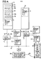
- FIG. 4 of the present case illustrates the above-referenced Tomlinson and Green multiprocessor system with modifications that incorporate the present invention.
- This Figure 4 system includes a pair of digital processors Pi and Pj which are coupled together via bus 50.
- Processor Pi is also coupled to a memory 51 via a high level language bus 52; and
- processor Pj is coupled to a memory 53 via a high level language bus 54.
- a program 55 which contains a sequence of high level language instructions 56.
- One of those instructions 56a is a CALL instruction which calls an activity A x Pi that processor Pi performs; while another of those instructions 56b is a CALL instruction which calls an activity AyPj that processor Pj performs.
- processor Pi executes the instructions 56 until it encounters one of the CALL instructions 56a or 56b.
- processor Pi interrogates an ACTIVITY RECORD 60 for the activity that is being called. That ACTIVITY RECORD is in a shared memory SM; and it is accessed via bus 50 through an intelligent memory controller IMC.
- each ACTIVITY RECORD 60 includes various FLAGS, a CALLER entry, an ACTIVITY QUEUE HEAD (AQH) entry, a NEXT IN QUEUE (NIQ) entry, and an ACTIVITY QUEUE TAIL (AQT) entry.
- processor Pj When processor Pj completes the execution of the activity that it was performing, it interrogates the PROCESSOR RECORDS and ACTIVITY RECORDS to determine which activity to execute next. All of the details of the actions that occur to determine which activity processor Pj performs next is described in the above-referenced Tomlinson and Green application in conjunction with TABLE 2.
- each activity record also includes an activity depictor 61.
- each depictor 61 is a pre-written thirty-two bit word in a random access memory or a thirty-two bit register in a register array.
- processor Pj selects an activity to perform, it then examines depictor 61 of the selected activity to determine how the activity is implemented and how it can be accessed.
- depictor 61 contains a portion "b" which indicates whether the corresponding activity is implemented via a high level language program, a low level language microcode program, or a hardware logic unit. Also preferably, depictor 61 contains a portion "c" which indicates how that activity can be accessed.
- processor Pj performs all of the previously described steps of Figure 2. Thus it examines portion "b" to determine whether the selected activity is implemented by a software program 71, a firmware program 72, or a hardware logic unit 73. Then it utilizes the information in portion "c" to activate the activity as indicated at 34a-36b.
- processor Pi calls an activity which it performs
- the processor then examines the depictor for that activity to determine whether it is implemented by a software program 74, a microcode program 75, or a hardware logic unit 76. Then, depending on that determination, it performs steps 34a-34b, 35a-35b, or 36a-36b of Figure 2.
- the multiprocessor system of Figure 4 has both the versatility and changeability features of the single processor system of Figure 1. If high speed is the primary design goal of the Figure 4 system, then the frequently used activities should be implemented by low level language microcode programs or hardware logic units. And the performance of the multiprocessor system can be enhanced with time by substituting low level language programs or hardware logic units for various activities that previously had been implemented by high level language software programs, and by providing new activity depictors 61 in the activity's record 60 to reflect this change.
Landscapes
- Engineering & Computer Science (AREA)
- Software Systems (AREA)
- Theoretical Computer Science (AREA)
- Physics & Mathematics (AREA)
- General Engineering & Computer Science (AREA)
- General Physics & Mathematics (AREA)
- Executing Machine-Instructions (AREA)
Applications Claiming Priority (2)
| Application Number | Priority Date | Filing Date | Title |
|---|---|---|---|
| US06/528,461 US4862351A (en) | 1983-09-01 | 1983-09-01 | Method of executing called activities via depictor-linked low level language microcode, hardware logic, and high level language commands; and apparatus for same |
| US528461 | 1983-09-01 |
Publications (3)
| Publication Number | Publication Date |
|---|---|
| EP0138352A2 true EP0138352A2 (de) | 1985-04-24 |
| EP0138352A3 EP0138352A3 (en) | 1988-03-16 |
| EP0138352B1 EP0138352B1 (de) | 1991-06-19 |
Family
ID=24105774
Family Applications (1)
| Application Number | Title | Priority Date | Filing Date |
|---|---|---|---|
| EP84305968A Expired - Lifetime EP0138352B1 (de) | 1983-09-01 | 1984-08-31 | Verfahren zum Betrieb einer Datenverarbeitungsanlage über "Depictor" verbundene Mikrobefehle und logische Schaltungen |
Country Status (5)
| Country | Link |
|---|---|
| US (1) | US4862351A (de) |
| EP (1) | EP0138352B1 (de) |
| CA (1) | CA1214565A (de) |
| DE (1) | DE3484725D1 (de) |
| WO (1) | WO1985001136A1 (de) |
Cited By (6)
| Publication number | Priority date | Publication date | Assignee | Title |
|---|---|---|---|---|
| GB2231986A (en) * | 1989-03-27 | 1990-11-28 | Gen Electric | Programmable logic controller including function block processor and bit processor |
| GB2232514A (en) * | 1989-04-24 | 1990-12-12 | Yokogawa Electric Corp | Programmable controller |
| EP0387172A3 (de) * | 1989-03-06 | 1992-04-22 | International Business Machines Corporation | Prozeduranrufschnittstelle |
| EP0414624A3 (en) * | 1989-08-24 | 1992-05-13 | International Business Machines Corporation | System for calling procedures on a remote network node |
| US5218699A (en) * | 1989-08-24 | 1993-06-08 | International Business Machines Corporation | Remote procedure calls in heterogeneous systems |
| EP0684547A3 (de) * | 1994-05-16 | 1996-12-11 | Compaq Computer Corp | Videosteuerschaltung für mehrere Videosteuergeräte. |
Families Citing this family (11)
| Publication number | Priority date | Publication date | Assignee | Title |
|---|---|---|---|---|
| AU597980B2 (en) * | 1986-05-30 | 1990-06-14 | Honeywell Bull Inc. | Apparatus and method for interprocessor communication |
| JPS63278145A (ja) * | 1987-05-11 | 1988-11-15 | Nec Corp | パラメ−タ対応検査方式 |
| US4961133A (en) * | 1987-11-06 | 1990-10-02 | Visystems, Inc. | Method for providing a virtual execution environment on a target computer using a virtual software machine |
| AU4414889A (en) * | 1988-10-21 | 1990-05-14 | A.C. Nielsen Company | Software operating environment |
| JPH02190930A (ja) * | 1988-12-29 | 1990-07-26 | Internatl Business Mach Corp <Ibm> | ソフトウエア命令実行装置 |
| GB2242293A (en) * | 1990-01-05 | 1991-09-25 | Apple Computer | Apparatus and method for dynamic linking of computer software components |
| JPH0831041B2 (ja) * | 1991-09-06 | 1996-03-27 | インターナショナル・ビジネス・マシーンズ・コーポレイション | プログラム条件処理方法およびコンピュータ・システム |
| US5319784A (en) * | 1991-12-18 | 1994-06-07 | International Business Machines Corp. | System for automatic and selective compile-time installation of fastpath into program for calculation of function/procedure without executing the function/procedure |
| US5409200A (en) * | 1992-03-05 | 1995-04-25 | Zingher; Arthur R. | Printed-circuit-like array of springs with non-linear force vs deflection |
| US6542854B2 (en) * | 1999-04-30 | 2003-04-01 | Oracle Corporation | Method and mechanism for profiling a system |
| GB2412192B (en) * | 2004-03-18 | 2007-08-29 | Advanced Risc Mach Ltd | Function calling mechanism |
Family Cites Families (17)
| Publication number | Priority date | Publication date | Assignee | Title |
|---|---|---|---|---|
| US3478322A (en) * | 1967-05-23 | 1969-11-11 | Ibm | Data processor employing electronically changeable control storage |
| US3983539A (en) * | 1969-05-19 | 1976-09-28 | Burroughs Corporation | Polymorphic programmable units employing plural levels of sub-instruction sets |
| US3614745A (en) * | 1969-09-15 | 1971-10-19 | Ibm | Apparatus and method in a multiple operand stream computing system for identifying the specification of multitasks situations and controlling the execution thereof |
| US3631405A (en) * | 1969-11-12 | 1971-12-28 | Honeywell Inc | Sharing of microprograms between processors |
| BE758813A (fr) * | 1969-11-28 | 1971-04-16 | Burroughs Corp | Structures de programme pour la mise en oeuvre de systemes de traitement d'information, communes a des langages de programme de niveau plus eleve |
| US3735363A (en) * | 1971-04-07 | 1973-05-22 | Burroughs Corp | Information processing system employing stored microprogrammed processors and access free field memories |
| BE795789A (fr) * | 1972-03-08 | 1973-06-18 | Burroughs Corp | Microprogramme comportant une micro-instruction de recouvrement |
| US4131941A (en) * | 1977-08-10 | 1978-12-26 | Itek Corporation | Linked microprogrammed plural processor system |
| US4149243A (en) * | 1977-10-20 | 1979-04-10 | International Business Machines Corporation | Distributed control architecture with post and wait logic |
| JPS54104251A (en) * | 1978-02-02 | 1979-08-16 | Toshiba Corp | Data processor |
| US4257096A (en) * | 1978-10-23 | 1981-03-17 | International Business Machines Corporation | Synchronous and conditional inter-program control apparatus for a computer system |
| US4325121A (en) * | 1978-11-17 | 1982-04-13 | Motorola, Inc. | Two-level control store for microprogrammed data processor |
| US4253145A (en) * | 1978-12-26 | 1981-02-24 | Honeywell Information Systems Inc. | Hardware virtualizer for supporting recursive virtual computer systems on a host computer system |
| US4454579A (en) * | 1981-09-11 | 1984-06-12 | Data General Corporation | System for performing call and return operations |
| US4454580A (en) * | 1981-09-16 | 1984-06-12 | International Business Machines Corporation | Program call method and call instruction execution apparatus |
| US4484272A (en) * | 1982-07-14 | 1984-11-20 | Burroughs Corporation | Digital computer for executing multiple instruction sets in a simultaneous-interleaved fashion |
| US4463423A (en) * | 1982-07-14 | 1984-07-31 | Burroughs Corporation | Method of transforming high level language statements into multiple lower level language instruction sets |
-
1983
- 1983-09-01 US US06/528,461 patent/US4862351A/en not_active Expired - Lifetime
-
1984
- 1984-08-30 WO PCT/US1984/001387 patent/WO1985001136A1/en not_active Ceased
- 1984-08-30 CA CA000462175A patent/CA1214565A/en not_active Expired
- 1984-08-31 EP EP84305968A patent/EP0138352B1/de not_active Expired - Lifetime
- 1984-08-31 DE DE8484305968T patent/DE3484725D1/de not_active Expired - Lifetime
Cited By (8)
| Publication number | Priority date | Publication date | Assignee | Title |
|---|---|---|---|---|
| EP0387172A3 (de) * | 1989-03-06 | 1992-04-22 | International Business Machines Corporation | Prozeduranrufschnittstelle |
| GB2231986A (en) * | 1989-03-27 | 1990-11-28 | Gen Electric | Programmable logic controller including function block processor and bit processor |
| GB2231986B (en) * | 1989-03-27 | 1993-10-27 | G E Fanuc Automation North Ame | Programmable logic controller including a function block processor and a bit processor |
| GB2232514A (en) * | 1989-04-24 | 1990-12-12 | Yokogawa Electric Corp | Programmable controller |
| GB2232514B (en) * | 1989-04-24 | 1993-09-01 | Yokogawa Electric Corp | Programmable controller |
| EP0414624A3 (en) * | 1989-08-24 | 1992-05-13 | International Business Machines Corporation | System for calling procedures on a remote network node |
| US5218699A (en) * | 1989-08-24 | 1993-06-08 | International Business Machines Corporation | Remote procedure calls in heterogeneous systems |
| EP0684547A3 (de) * | 1994-05-16 | 1996-12-11 | Compaq Computer Corp | Videosteuerschaltung für mehrere Videosteuergeräte. |
Also Published As
| Publication number | Publication date |
|---|---|
| DE3484725D1 (de) | 1991-07-25 |
| CA1214565A (en) | 1986-11-25 |
| EP0138352A3 (en) | 1988-03-16 |
| WO1985001136A1 (en) | 1985-03-14 |
| US4862351A (en) | 1989-08-29 |
| EP0138352B1 (de) | 1991-06-19 |
Similar Documents
| Publication | Publication Date | Title |
|---|---|---|
| US4862351A (en) | Method of executing called activities via depictor-linked low level language microcode, hardware logic, and high level language commands; and apparatus for same | |
| DE69126166T2 (de) | Programmierbare Steuerungsvorrichtung | |
| US4323963A (en) | Hardware interpretive mode microprocessor | |
| US3878513A (en) | Data processing method and apparatus using occupancy indications to reserve storage space for a stack | |
| JP3552443B2 (ja) | 2つのアーキテクチャ間でプログラム制御を転送する方法及びシステム | |
| JP3649470B2 (ja) | データ処理装置 | |
| US5701493A (en) | Exception handling method and apparatus in data processing systems | |
| US3736567A (en) | Program sequence control | |
| US5634046A (en) | General purpose use of a stack pointer register | |
| JPS6040067B2 (ja) | 分散制御型多重処理システム | |
| JP2001508909A (ja) | バーチャルマシン命令を処理するためのデータ処理装置 | |
| US4279016A (en) | Instruction pre-fetch microprocessor interrupt system | |
| US3698007A (en) | Central processor unit having simulative interpretation capability | |
| CA1161566A (en) | Jump return stack | |
| EP0240108A2 (de) | Datenverarbeitungssystem | |
| US6502181B1 (en) | Method and apparatus for an enhanced processor | |
| EP0417916B1 (de) | Prozedurzustandsdeskriptorsystem für digitale Datenprozessoren | |
| JPS6079462A (ja) | 複数のレコ−ドへのアクセスを制御するコントロ−ラ | |
| US5893928A (en) | Data movement apparatus and method | |
| JPS6049352B2 (ja) | デ−タ処理装置 | |
| JPS61184643A (ja) | 仮想計算機の起動制御方式 | |
| JP2727023B2 (ja) | 情報処理装置 | |
| Bock | An interrupt control for the B5000 data processor system | |
| JPH0731527B2 (ja) | プログラマブルコントロ−ラ | |
| AU540728B2 (en) | Stack for a data processor |
Legal Events
| Date | Code | Title | Description |
|---|---|---|---|
| PUAI | Public reference made under article 153(3) epc to a published international application that has entered the european phase |
Free format text: ORIGINAL CODE: 0009012 |
|
| AK | Designated contracting states |
Designated state(s): BE DE FR GB IT NL SE |
|
| RAP1 | Party data changed (applicant data changed or rights of an application transferred) |
Owner name: UNISYS CORPORATION |
|
| PUAL | Search report despatched |
Free format text: ORIGINAL CODE: 0009013 |
|
| AK | Designated contracting states |
Kind code of ref document: A3 Designated state(s): BE DE FR GB IT NL SE |
|
| 17P | Request for examination filed |
Effective date: 19840913 |
|
| 17Q | First examination report despatched |
Effective date: 19890919 |
|
| GRAA | (expected) grant |
Free format text: ORIGINAL CODE: 0009210 |
|
| AK | Designated contracting states |
Kind code of ref document: B1 Designated state(s): BE DE FR GB IT NL SE |
|
| PG25 | Lapsed in a contracting state [announced via postgrant information from national office to epo] |
Ref country code: SE Effective date: 19910619 Ref country code: NL Effective date: 19910619 Ref country code: IT Free format text: LAPSE BECAUSE OF FAILURE TO SUBMIT A TRANSLATION OF THE DESCRIPTION OR TO PAY THE FEE WITHIN THE PRESCRIBED TIME-LIMIT;WARNING: LAPSES OF ITALIAN PATENTS WITH EFFECTIVE DATE BEFORE 2007 MAY HAVE OCCURRED AT ANY TIME BEFORE 2007. THE CORRECT EFFECTIVE DATE MAY BE DIFFERENT FROM THE ONE RECORDED. Effective date: 19910619 Ref country code: BE Effective date: 19910619 |
|
| ET | Fr: translation filed | ||
| REF | Corresponds to: |
Ref document number: 3484725 Country of ref document: DE Date of ref document: 19910725 |
|
| NLV1 | Nl: lapsed or annulled due to failure to fulfill the requirements of art. 29p and 29m of the patents act | ||
| PLBE | No opposition filed within time limit |
Free format text: ORIGINAL CODE: 0009261 |
|
| STAA | Information on the status of an ep patent application or granted ep patent |
Free format text: STATUS: NO OPPOSITION FILED WITHIN TIME LIMIT |
|
| 26N | No opposition filed | ||
| PGFP | Annual fee paid to national office [announced via postgrant information from national office to epo] |
Ref country code: FR Payment date: 20010802 Year of fee payment: 18 |
|
| REG | Reference to a national code |
Ref country code: GB Ref legal event code: IF02 |
|
| PGFP | Annual fee paid to national office [announced via postgrant information from national office to epo] |
Ref country code: GB Payment date: 20020626 Year of fee payment: 19 |
|
| PG25 | Lapsed in a contracting state [announced via postgrant information from national office to epo] |
Ref country code: FR Free format text: LAPSE BECAUSE OF NON-PAYMENT OF DUE FEES Effective date: 20030430 |
|
| REG | Reference to a national code |
Ref country code: FR Ref legal event code: ST |
|
| PGFP | Annual fee paid to national office [announced via postgrant information from national office to epo] |
Ref country code: DE Payment date: 20030829 Year of fee payment: 20 |
|
| PG25 | Lapsed in a contracting state [announced via postgrant information from national office to epo] |
Ref country code: GB Free format text: LAPSE BECAUSE OF NON-PAYMENT OF DUE FEES Effective date: 20030831 |
|
| GBPC | Gb: european patent ceased through non-payment of renewal fee |