EP0138475A2 - Improvements in and relating to reject handling in cyclones and other separator devices - Google Patents
Improvements in and relating to reject handling in cyclones and other separator devices Download PDFInfo
- Publication number
- EP0138475A2 EP0138475A2 EP84306608A EP84306608A EP0138475A2 EP 0138475 A2 EP0138475 A2 EP 0138475A2 EP 84306608 A EP84306608 A EP 84306608A EP 84306608 A EP84306608 A EP 84306608A EP 0138475 A2 EP0138475 A2 EP 0138475A2
- Authority
- EP
- European Patent Office
- Prior art keywords
- rejects
- outlet
- liquid
- chamber
- separator
- Prior art date
- Legal status (The legal status is an assumption and is not a legal conclusion. Google has not performed a legal analysis and makes no representation as to the accuracy of the status listed.)
- Withdrawn
Links
Images


Classifications
-
- B—PERFORMING OPERATIONS; TRANSPORTING
- B03—SEPARATION OF SOLID MATERIALS USING LIQUIDS OR USING PNEUMATIC TABLES OR JIGS; MAGNETIC OR ELECTROSTATIC SEPARATION OF SOLID MATERIALS FROM SOLID MATERIALS OR FLUIDS; SEPARATION BY HIGH-VOLTAGE ELECTRIC FIELDS
- B03B—SEPARATING SOLID MATERIALS USING LIQUIDS OR USING PNEUMATIC TABLES OR JIGS
- B03B11/00—Feed or discharge devices integral with washing or wet-separating equipment
-
- B—PERFORMING OPERATIONS; TRANSPORTING
- B04—CENTRIFUGAL APPARATUS OR MACHINES FOR CARRYING-OUT PHYSICAL OR CHEMICAL PROCESSES
- B04C—APPARATUS USING FREE VORTEX FLOW, e.g. CYCLONES
- B04C11/00—Accessories, e.g. safety or control devices, not otherwise provided for, e.g. regulators, valves in inlet or overflow ducting
-
- B—PERFORMING OPERATIONS; TRANSPORTING
- B04—CENTRIFUGAL APPARATUS OR MACHINES FOR CARRYING-OUT PHYSICAL OR CHEMICAL PROCESSES
- B04C—APPARATUS USING FREE VORTEX FLOW, e.g. CYCLONES
- B04C5/00—Apparatus in which the axial direction of the vortex is reversed
- B04C5/14—Construction of the underflow ducting; Apex constructions; Discharge arrangements ; discharge through sidewall provided with a few slits or perforations
- B04C5/18—Construction of the underflow ducting; Apex constructions; Discharge arrangements ; discharge through sidewall provided with a few slits or perforations with auxiliary fluid assisting discharge
-
- B—PERFORMING OPERATIONS; TRANSPORTING
- B04—CENTRIFUGAL APPARATUS OR MACHINES FOR CARRYING-OUT PHYSICAL OR CHEMICAL PROCESSES
- B04C—APPARATUS USING FREE VORTEX FLOW, e.g. CYCLONES
- B04C9/00—Combinations with other devices, e.g. fans, expansion chambers, diffusors, water locks
-
- D—TEXTILES; PAPER
- D21—PAPER-MAKING; PRODUCTION OF CELLULOSE
- D21D—TREATMENT OF THE MATERIALS BEFORE PASSING TO THE PAPER-MAKING MACHINE
- D21D5/00—Purification of the pulp suspension by mechanical means; Apparatus therefor
- D21D5/18—Purification of the pulp suspension by mechanical means; Apparatus therefor with the aid of centrifugal force
- D21D5/24—Purification of the pulp suspension by mechanical means; Apparatus therefor with the aid of centrifugal force in cyclones
Definitions
- the present invention relates to a method and apparatus for use in separating a liquid into accepts and rejects to thereby remove heavy or light contaminants from the liquid.
- the liquid may be a slurry of fibre and liquid and the contaminants may be droplets or fibres or other particles may be lighter or heavier than the liquid.
- Cyclones are commonly employed to separate such contaminants from a liquid.
- a slurry of paper fibres and water enters a conical separator, usually with its apex lower-most, by way of an inlet disposed remote from the apex.
- a vortex is formed within the conical chamber of the separator and heavy contaminant particles migrate to the wall of the cone and proceed downwards to the apex to be ejected from an outlet, together with a proportion of good paper fibre.
- the majority of fibre and water, substantially free from heavy contamination passes out of an axially disposed outlet passage disposed at the inlet end of the cone and opposite the apex.
- the fibre and water emerging from either outlet may be directed into a second chamber to undergo a further separation stage. It is also possible to remove a light fraction of the contaminants by employing an axial outlet pipe disposed co-axially, within the aforementioned water and fibre outlet, or at the apex co-axially with the apex orifice.
- the present invention aims to provide a means of minimising fibre loss in hydro-cyclones and/ or other separator devices with similar reject arrangements.
- a method of separating a liquid into accepts and rejects utilising a separator having an outlet for the rejects, which outlet opens into a rejects chamber, the method comprising feeding the liquid to be subject to the separation into the separator, passing a further liquid through the rejects chamber to carry away rejects passing through the rejects outlet from the separator, and controlling the liquid passing through the rejects chamber to thereby control the flow of liquid through the rejects outlet so as to prevent or substantially prevent the passage of accepts therethrough whilst allowing the passage of rejects therethrough.
- it is the pressure of the liquid flowing through the rejects chamber which is controlled, whilst according to another embodiment, it is the flow of liquid through the rejects chamber which is controlled.
- the rejects chamber forms part of a rejects loop which comprises a pump for circulating liquid round the loop and providing pressure in the rejects chamber, valves for controlling the flow rate of liquid in the loop and the pressure thereof, auxiliary separating means for removing contaminants from the liquid, and means for replacing any liquid removed, from the loop.
- the method can be employed in the removal of heavy or light rejects. That is to say, the reject loop may be applied to a lights outlet or to a heavies outlet. Thus, the contamination separated by the method may be heavies or lights according to the application.
- a method of separating heavy contaminants from a fibre and liquid slurry comprising passing the slurry to be decontaminated into a separator having an outlet for the heavy particles (rejects) which opens into a rejects chamber, passing liquid through the rejects chamber in order to carry away rejects falling through the opening, and controlling the flow of liquid through the reject chamber so that there is no or virtually no flow of liquid through the opening between the separator and reject chamber.
- More specifically one or more valves are set to control the pressure of the liquid flowing through the reject chamber in preference to controlling the flow.
- apparatus for controlling the passage of liquid through a rejects outlet of a separator for separating a liquid into accepts and rejects, the rejects outlet opening into a rejects chamber, means for passing a further liquid through the rejects chamber to carry away the rejects passing through the rejects outlet, and means controlling the liquid passing through the rejects chamber to thereby control the flow of liquid through the rejects outlet so as to prevent or substantially prevent the passage of accepts therethrough whilst allowing the passage of rejects therethrough.
- the means for passing the further liquid through the rejects chamber and the means controlling the liquid passing therethrough comprises inlet and outlet passages of a reject loop, a pump and respective valves.
- the pressure in the reject chamber can be controlled to thereby control passage of the accepts and rejects from the separator.
- apparatus for controlling the passage of liquid through the rejects outlet of a separator which apparatus comprises a passage or chamber into which the outlet opens and through which passage, liquid flows to carry away rejects falling through the opening, the flow of liquid through the passage being controlled such that there is substantially no flow of fibre and liquid slurry through the opening from the separator.
- the apparatus is particularly suitable for use with a cyclone separator but it may be used with any other separator having a similar reject arrangement.
- the apparatus is provided with means for controlling the pressure in the passage or chamber at the opening.
- the means comprises one or more valves in a circuit defining a rejects loop and incorporating the rejects chamber.
- the reject loop is preferably provided with its own auxiliary separator for removing contaminants franhe liquid in the rejects loop.
- the apparatus may be employed in the removal of heavy or light contaminants, with the rejects chamber positioned appropriately in each case i.e. at the lights outlet or at the heavies outlet.
- the rejects chamber is cylindrical in shape and coaxial with the rejects outlet of the separator.
- the inlet and outlet to the rejects chamber intersects the chamber tangentially or chordally and substantially at right angles to the axis of the separator outlet.
- the rejects chamber comprises a tubular passage whose axis is disposed at right angles to the axis of the rejects outlet.
- the invention also contemplates apparatus for separating a liquid into accepts and rejects comprising a separator device having an __inlet for the liquid which is to be subject to the separation, means producing a flow through the device with the rejects migrating to at least one outlet, and the accepts being recovered at another outlet, the at least one outlet for the rejects opening into a or a respective rejects passage or chamber, means passing a further liquid through the rejects chamber to carry away the rejects passing through the rejects outlet, and means controlling the liquid passing through the rejects chamber to thereby control the flow of liquid through the rejects outlet so as to prevent or substantially prevent the passage of accepts therethrough whilst allowing the passage of rejects therethrough.
- the pressure of the liquid flowing through the rejects chamber is controlled.
- the flow of liquid through the rejects chamber is controlled.
- apparatus for removing heavy contamination from a fibre and liquid slurry comprising a separator device having an inlet for the fibre and liquid slurry, means producing a flow through the device with the heavy contaminants migrating to an outlet, and the fibre and liquid slurry substantially free from heavy contaminants being recovered at another outlet, the outlet for the repots opening into a passage or chamber through which liquid flows to carry away the rejects which fall through the opening, the flow of liquid through the passage or chamber being controlled such that there is substantially no flow of fibre and liquid slurry through the opening.
- the rejects chamber is preferably part of a rejects loop incorporating a pump and valves for circulating liquid round the loop and controlling the pressure and/or flow of the liquid.
- the rejects outlet is preferably disposed downwardly of the inlet and the heavy contaminants fall through the rejects outlet opening into the rejects chamber.
- the apparatus is for removing light contaminants the arrangement is inverted and the contaminants float upwardly to the reject outlet.
- the separator is designed to remove both heavy and light contaminants, for example a reverse vortex separator for heavies removal followed downstream by a Uniflow cleaner for lights removal, two outlets are provided at opposite, upper and lower ends of the apparatus, each leading to a respective lights reject chamber and a heavies reject chamber.
- valves are employed to control the flow and pressure of the liquid passing through the rejects chamber and this may be controlled automatically by providing sensors measuring the flow or pressure characteristics or the volume of liquid in the rejects loop and comparing the measured values with desired values.
- a separator in the form of a cyclone separator is shown at 1.
- the separator is conical with its apex lowermost and has an outlet 8 at the apex 5.
- An inlet is shown at 2 and another outlet at 6.
- the orifice 8 opens into a cylindrical chamber 7 which is disposed coaxially with respect to the axis of the conical separator 1.
- the chamber 7 is provided with an inlet passage 10 and an outlet passage 9.
- the inlet and outlet passages intersect tangentially or chordally with the chamber 7.
- the chamber 7 forms part of a rejects loop one example of which is shown in Figure 3.
- Figure 2c shows an alternative construction in which the passages 9,10 serve as the chamber 7. That is to say the chamber 7 is tubular, rather than cylindrical, and is disposed with its axis at right angles to the axis of the opening, which axes intersect with one another.
- the separator 1 operates on the reverse vortex principle that is to say the contaminated paper fibre and liquid slurry enter the separator by way of the inlet 2 and a downwardly spiralling vortex is generated within the separator which causes the heavies to migrate to the wall 4 of the separator and proceed downwards to the apex 5.
- the fibre and liquid substantially free of heavies move upwardly and emerge from the outlet 6.
- the present invention provides a means of recovering the heavies whilst preventing the removal of fibre and water from the outlet opening 8. This is achieved by passing liquid through the rejects chamber in a controlled manner such that any tendency for the liquid in the separator to pass out of the opening is countered by the pressure exerted by the liquid flowing in the loop. In practice this is achieved by adjusting the flow rate and pressure of the liquid in the rejects loop. Valves 11,12 and 20 are provided for this purpose.
- the circuit comprises:- a tank 14 containing a suitable liquid such as water; a pump 15 for circulating the water round the circuit; and an auxiliary separator 16 for removing in this example heavies from the water in the circuit of the rejects loop.
- the outlet 9 from the rejects chamber incorporates valves 12 and 20 and leads to the tank 14.
- the inlet 10 to the rejects chamber feeds from the tank 14 by way of the auxiliary separator 16 and, valves 11 and 17 are provided to control the flow rate.
- the pressure value is set by the valve 20.
- the system may be set up as described hereinbelow for which purpose reference is made to the pressure in the rejects chamber as measured by the pressure gauge 13.
- Valves 11 and 12 are closed and the conical separator 1 operated under its normal conditions. There will be flow through the orifices 6 and 2 but not into chamber 7.
- the pressure P R is recorded.
- Valves 18 and 19 are then closed and valves 11, 12 and 20 opened.
- Pump 15 is started and the setting of valve 20 is adjusted so that the value of P R is the same as recorded previously but with a substantial flow round the rejects loop.
- the pump can then be stopped. Having set the valves and pressures the complete system can be operated.
- the reject loop pump is started and shortly afterwards the conical separator pump is started, valves 18, 19, 11 and 12 having been opened, and valve 20 having been left at the setting achieved as above.
- a level control device consisting of sensor 25, control unit 26, and motorized valve 20 controls the pressure P R in chamber 7 such that there is no flow through the orifice 8.
- valve 20 As an increase in level 24 demands the'closure of valve 20 the system is exactly the same as an ordinary level control.
- a by-pass balve, 31 has been found useful in setting up experiments. In trials using automatic level control of valve 20 it enables the valve always to be oscillating about its mid-position under normal operating conditions, and it also serves to ensure that the reject loop is never closed. This protects the system from full pump pressure if the valve becomes closed due to system instability or operator error.
- a by-pass valve 31 is likewise included in the arrangement shown in Figs. 5 and 6.
- An alternative control system requires a microprocessor (27) programmed with the known balanced pressures PAPF and PR ( Figure 5) which controls P R by adjusting valve 20.
- a further method would be to add a short parallel or conical extension below orifice 8 (Figure 6), 29 and monitor the interface 30 between rejects loop water, which is substantially clear and stock in the separator which is substantially cloudy.
- the rejects loop could be loaded with some tracer material to sharpen the interface.
- Dye was used in the transparent version.
- Production versions could use magnetic, optical, ultrasonic, radioactive, visual or other sensing at 28.
- the sensor 28 could also be a small flowmeter. By whatever means the sensor passes a signal to control 27 which regulates pressure P R by operating valve 20 in order to prevent substantial flow through orifice 8.
- FIGs 7a and 7b there are shown apparatus for use in removing "lights" contamination from a liquid, such as a fibre and liquid slurry.
- a liquid such as a fibre and liquid slurry.
- Such lights contamination may be plastics material or oil particles.
- the apparatus of Figure 7a comprises a separator chamber 35 having an inlet 2' for the liquid to be cleaned, an outlet 37 for the lights rejects and an outlet 39 for the decontaminated liquid.
- the outlet 37 for the lights rejects leads into a rejects chamber 41 which may have a configuration corresponding to the arrangements described in Figures 2a,2b or 2c.
- the separator is of the Uniflow direction type.
- the lights removal apparatus is the arrangement of Figure 1 inverted and the integers of the rejects loop correspond to those described with reference to Figure 3, with corresponding valves 11', 12' and 20' for controlling the pressure and flow in the rejects chamber 41.
- a cleaner 16' is also provided for cleaning the liquid in the rejects loop. This comprises a light rejects removal apparatus.
- the other integers of the apparatus are identified with reference numbers corresponding to those used in Figures 1, 2 and 3.
- the apparatus of Figure 7b likewise comprises a separator, identified as 35" and has an inlet 2" for the liquid to be cleaned, an outlet 37" for the lights rejects and an outlet 39" for the decontaminated liquid.
- the separator is conical with the outlet 39" lowermost at the apex, and the inlet 2" and the outlet 37" at the other end.
- the outlet 37" feeds into a rejects chamber 41".
- the rejects chamber 41" is part of a rejects loop having an inlet 10" and outlet 9" which is essentially the same as that described with reference to Figure 7a.
- a different configuration of auxiliary separator 16" is employed.
- the separator 35" and auxiliary separator 16" are reverse lights separators.
Landscapes
- Engineering & Computer Science (AREA)
- Mechanical Engineering (AREA)
- Cyclones (AREA)
- Paper (AREA)
- Electrical Discharge Machining, Electrochemical Machining, And Combined Machining (AREA)
- Centrifugal Separators (AREA)
Abstract
A method and apparatus for increasing the yield in the separating of heavy or light contamination from a liquid. The liquid is separated into accepts and rejects and the rejects outlet (8, 37) from the separator (1) opens into a rejects chamber (7) which forms part of a rejects loop. The loop includes valves (11, 12, 20) and a pump (15) which enable the pressure in the rejects chamber to be controlled so that there is substantially no flow of accepts from the separator to the rejects chamber, whilst the contaminant rejects are allowed to pass from the separator to the rejects chamber. The reject loop preferably includes an auxiliary separator (16) for removing contaminants from the loop.
Description
- The present invention relates to a method and apparatus for use in separating a liquid into accepts and rejects to thereby remove heavy or light contaminants from the liquid. The liquid may be a slurry of fibre and liquid and the contaminants may be droplets or fibres or other particles may be lighter or heavier than the liquid.
- Cyclones are commonly employed to separate such contaminants from a liquid. When this is done in the manufature of paper for the removal of contaminants denser than the liquid, a slurry of paper fibres and water, at about 0.7% by weight of fibre, enters a conical separator, usually with its apex lower-most, by way of an inlet disposed remote from the apex. A vortex is formed within the conical chamber of the separator and heavy contaminant particles migrate to the wall of the cone and proceed downwards to the apex to be ejected from an outlet, together with a proportion of good paper fibre. The majority of fibre and water, substantially free from heavy contamination passes out of an axially disposed outlet passage disposed at the inlet end of the cone and opposite the apex. The fibre and water emerging from either outlet may be directed into a second chamber to undergo a further separation stage. It is also possible to remove a light fraction of the contaminants by employing an axial outlet pipe disposed co-axially, within the aforementioned water and fibre outlet, or at the apex co-axially with the apex orifice.
- One of the disadvantages of this type of cleaner is that a substantial percentage of good fibre escapes with the heavy rejects making it necessary to provide secondary, tertiary and sometimes quaternary banks of cleaners to recover the good fibre. This gives rise to additional pumping and capital costs which are undesirable. The present invention aims to provide a means of minimising fibre loss in hydro-cyclones and/ or other separator devices with similar reject arrangements.
- According to one aspect of the present invention there is provided a method of separating a liquid into accepts and rejects utilising a separator having an outlet for the rejects, which outlet opens into a rejects chamber, the method comprising feeding the liquid to be subject to the separation into the separator, passing a further liquid through the rejects chamber to carry away rejects passing through the rejects outlet from the separator, and controlling the liquid passing through the rejects chamber to thereby control the flow of liquid through the rejects outlet so as to prevent or substantially prevent the passage of accepts therethrough whilst allowing the passage of rejects therethrough.
- Whilst it is desired to prevent the passage of accepts, it will be appreciated that a small quantity of accepts may pass from the separator to the rejects chamber along with the rejects. However, the passage of accepts from the separator is considerably reduced by comparison with that which occurs in conventional separators not utilising the features of the present invention.
- According to one embodiment it is the pressure of the liquid flowing through the rejects chamber which is controlled, whilst according to another embodiment, it is the flow of liquid through the rejects chamber which is controlled.
- Conveniently, the rejects chamber forms part of a rejects loop which comprises a pump for circulating liquid round the loop and providing pressure in the rejects chamber, valves for controlling the flow rate of liquid in the loop and the pressure thereof, auxiliary separating means for removing contaminants from the liquid, and means for replacing any liquid removed, from the loop.
- The method can be employed in the removal of heavy or light rejects. That is to say, the reject loop may be applied to a lights outlet or to a heavies outlet. Thus, the contamination separated by the method may be heavies or lights according to the application.
- According to one embodiment of the invention then, there is provided a method of separating heavy contaminants from a fibre and liquid slurry comprising passing the slurry to be decontaminated into a separator having an outlet for the heavy particles (rejects) which opens into a rejects chamber, passing liquid through the rejects chamber in order to carry away rejects falling through the opening, and controlling the flow of liquid through the reject chamber so that there is no or virtually no flow of liquid through the opening between the separator and reject chamber.
- More specifically one or more valves are set to control the pressure of the liquid flowing through the reject chamber in preference to controlling the flow.
- According to another aspect of the invention there is provided apparatus for controlling the passage of liquid through a rejects outlet of a separator for separating a liquid into accepts and rejects, the rejects outlet opening into a rejects chamber, means for passing a further liquid through the rejects chamber to carry away the rejects passing through the rejects outlet, and means controlling the liquid passing through the rejects chamber to thereby control the flow of liquid through the rejects outlet so as to prevent or substantially prevent the passage of accepts therethrough whilst allowing the passage of rejects therethrough.
- The means for passing the further liquid through the rejects chamber and the means controlling the liquid passing therethrough comprises inlet and outlet passages of a reject loop, a pump and respective valves. By means of the pump and valves the pressure in the reject chamber can be controlled to thereby control passage of the accepts and rejects from the separator.
- According to one embodiment of the invention there is provided apparatus for controlling the passage of liquid through the rejects outlet of a separator, which apparatus comprises a passage or chamber into which the outlet opens and through which passage, liquid flows to carry away rejects falling through the opening, the flow of liquid through the passage being controlled such that there is substantially no flow of fibre and liquid slurry through the opening from the separator.
- The apparatus is particularly suitable for use with a cyclone separator but it may be used with any other separator having a similar reject arrangement. The apparatus is provided with means for controlling the pressure in the passage or chamber at the opening.
- Conveniently, the means comprises one or more valves in a circuit defining a rejects loop and incorporating the rejects chamber. The reject loop is preferably provided with its own auxiliary separator for removing contaminants franthe liquid in the rejects loop. The apparatus may be employed in the removal of heavy or light contaminants, with the rejects chamber positioned appropriately in each case i.e. at the lights outlet or at the heavies outlet.
- In one embodiment the rejects chamber is cylindrical in shape and coaxial with the rejects outlet of the separator. The inlet and outlet to the rejects chamber intersects the chamber tangentially or chordally and substantially at right angles to the axis of the separator outlet. In another embodiment the rejects chamber comprises a tubular passage whose axis is disposed at right angles to the axis of the rejects outlet.
- The invention also contemplates apparatus for separating a liquid into accepts and rejects comprising a separator device having an __inlet for the liquid which is to be subject to the separation, means producing a flow through the device with the rejects migrating to at least one outlet, and the accepts being recovered at another outlet, the at least one outlet for the rejects opening into a or a respective rejects passage or chamber, means passing a further liquid through the rejects chamber to carry away the rejects passing through the rejects outlet, and means controlling the liquid passing through the rejects chamber to thereby control the flow of liquid through the rejects outlet so as to prevent or substantially prevent the passage of accepts therethrough whilst allowing the passage of rejects therethrough.
- According to one embodiment the pressure of the liquid flowing through the rejects chamber is controlled.
- According to another embodiment the flow of liquid through the rejects chamber is controlled.
- According to another embodiment of the invention there is provided apparatus for removing heavy contamination from a fibre and liquid slurry, comprising a separator device having an inlet for the fibre and liquid slurry, means producing a flow through the device with the heavy contaminants migrating to an outlet, and the fibre and liquid slurry substantially free from heavy contaminants being recovered at another outlet, the outlet for the repots opening into a passage or chamber through which liquid flows to carry away the rejects which fall through the opening, the flow of liquid through the passage or chamber being controlled such that there is substantially no flow of fibre and liquid slurry through the opening.
- The rejects chamber is preferably part of a rejects loop incorporating a pump and valves for circulating liquid round the loop and controlling the pressure and/or flow of the liquid.
- Where the apparatus is solely for removing heavy contamination, then the rejects outlet is preferably disposed downwardly of the inlet and the heavy contaminants fall through the rejects outlet opening into the rejects chamber.
- Where the apparatus is for removing light contaminants the arrangement is inverted and the contaminants float upwardly to the reject outlet.
- Where the separator is designed to remove both heavy and light contaminants, for example a reverse vortex separator for heavies removal followed downstream by a Uniflow cleaner for lights removal, two outlets are provided at opposite, upper and lower ends of the apparatus, each leading to a respective lights reject chamber and a heavies reject chamber.
- By virtue of the invention contaminants are removed in an efficient manner with virtually zero fibre loss.
- valves are employed to control the flow and pressure of the liquid passing through the rejects chamber and this may be controlled automatically by providing sensors measuring the flow or pressure characteristics or the volume of liquid in the rejects loop and comparing the measured values with desired values.
- The present invention will now be described further, by way of example only, with reference to the accompanying drawings; in which:-
- Figure 1 is a schematic illustration of the rejects handling device according to one aspect of the present invention for removing "heavies" contamination; Figures 2a, 2b and 2c are views looking in the direction of arrow A of Figure 1 showing three alternative constructions;
- Figure 3 is a schematic arrangement of apparatus according to the invention showing the reject loop circuit;
- Figures 4, 5 and 6 are schematic diagrams showing alternative arrangements for maintaining the desired flow characteristics, and
- Figures 7a and 7b are schematic illustrations of two embodiments of reject handling devices according to the present invention for removing "lights" contamination.
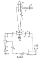
- Referring to Figure 1 a separator in the form of a cyclone separator is shown at 1. The separator is conical with its apex lowermost and has an
outlet 8 at theapex 5. An inlet is shown at 2 and another outlet at 6. Theorifice 8 opens into acylindrical chamber 7 which is disposed coaxially with respect to the axis of theconical separator 1. Thechamber 7 is provided with aninlet passage 10 and anoutlet passage 9. As shown in Figures 2a and 2b, the inlet and outlet passages intersect tangentially or chordally with thechamber 7. Thechamber 7 forms part of a rejects loop one example of which is shown in Figure 3. Figure 2c shows an alternative construction in which thepassages chamber 7. That is to say thechamber 7 is tubular, rather than cylindrical, and is disposed with its axis at right angles to the axis of the opening, which axes intersect with one another. - In the example illustrated in Figure 1 the
separator 1 operates on the reverse vortex principle that is to say the contaminated paper fibre and liquid slurry enter the separator by way of theinlet 2 and a downwardly spiralling vortex is generated within the separator which causes the heavies to migrate to thewall 4 of the separator and proceed downwards to theapex 5. The fibre and liquid substantially free of heavies move upwardly and emerge from theoutlet 6. - According to the described embodiment the present invention provides a means of recovering the heavies whilst preventing the removal of fibre and water from the outlet opening 8. This is achieved by passing liquid through the rejects chamber in a controlled manner such that any tendency for the liquid in the separator to pass out of the opening is countered by the pressure exerted by the liquid flowing in the loop. In practice this is achieved by adjusting the flow rate and pressure of the liquid in the rejects loop. Valves 11,12 and 20 are provided for this purpose.
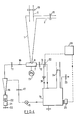
- One arrangement for the rejects loop is shown in Figure 3. The circuit comprises:- a
tank 14 containing a suitable liquid such as water; apump 15 for circulating the water round the circuit; and anauxiliary separator 16 for removing in this example heavies from the water in the circuit of the rejects loop. Theoutlet 9 from the rejects chamber incorporatesvalves tank 14. Theinlet 10 to the rejects chamber feeds from thetank 14 by way of theauxiliary separator 16 and,valves valve 20. - The system may be set up as described hereinbelow for which purpose reference is made to the pressure in the rejects chamber as measured by the
pressure gauge 13. -
Valves conical separator 1 operated under its normal conditions. There will be flow through theorifices chamber 7. The pressure PR is recorded.Valves valves Pump 15 is started and the setting ofvalve 20 is adjusted so that the value of PR is the same as recorded previously but with a substantial flow round the rejects loop. The pump can then be stopped. Having set the valves and pressures the complete system can be operated. The reject loop pump is started and shortly afterwards the conical separator pump is started,valves valve 20 having been left at the setting achieved as above. - When the steady state is reached a zero or negligible flow will exist through
orifice 8 and the value of PR will be as recorded in the two setting up operations. Heavy contaminant migrates to thewall 4 and eventually to thetip 5 of the separator. Although there is virtually no flow throughorifice 8, the contaminant particles fall through intochamber 7 because of their density and system pressure fluctuations and are carried away in the rejects loop. To prevent an unacceptable build-up of contamination in the loop the auxiliary cyclone, 16, is included in the rejects loop. This has arejects chamber 21 below its conical apex, similar tochamber 7, but instead of a through flow the only exit from the chamber is via valve(s) 22 which are periodically opened to purge the chamber and the loop. Liquid loss is made up usingvalve 23. - Trials with the above apparatus operated successfully on paper stock containing artificial plastic particles. These were effectively removed and the fibre loss in the reject loop was found to be of the order of zero to 1.4% depending on contaminant concentration. A similar test using a cyclone cleaner without the controlled orifice of the present invention rejected between 11% and 18% of fibre. The test apparatus was a full size device but constructed of transparent material which simplifies the setting up and operating procedure.
- It is envisaged that in practice a commercial cleaner would require some system to control the
valve 20 and to control periodic dumping of the auxiliary cleaner throughvalve 22. This could be done in several ways and reference is made in the following description to Figure 4, 5 or 6 which illustrate various alternative arrangements. - If there is no flow into the rejects loop the level in the
tank 14, at 24 see Figure 4, will remain unchanged providedvalves 22 remain shut. Any increase or decrease in the tank level will therefore be due to flow through theorifice 8 from the separator. - The criteria of zero flow through the
orifice 8 therefore can simply be maintained by a level control system (Figure 4). As we are concerned only with small volume changes the free surface oftank 14 must be small to get the required sensitivity. A level control device consisting ofsensor 25,control unit 26, andmotorized valve 20 controls the pressure PR inchamber 7 such that there is no flow through theorifice 8. - As an increase in
level 24 demands the'closure ofvalve 20 the system is exactly the same as an ordinary level control. A by-pass balve, 31, has been found useful in setting up experiments. In trials using automatic level control ofvalve 20 it enables the valve always to be oscillating about its mid-position under normal operating conditions, and it also serves to ensure that the reject loop is never closed. This protects the system from full pump pressure if the valve becomes closed due to system instability or operator error. - A by-
pass valve 31 is likewise included in the arrangement shown in Figs. 5 and 6. - An alternative control system requires a microprocessor (27) programmed with the known balanced pressures PAPF and PR (Figure 5) which controls PR by adjusting
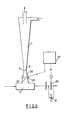
valve 20. - A further method would be to add a short parallel or conical extension below orifice 8 (Figure 6), 29 and monitor the
interface 30 between rejects loop water, which is substantially clear and stock in the separator which is substantially cloudy. The rejects loop could be loaded with some tracer material to sharpen the interface. Dye was used in the transparent version. Production versions could use magnetic, optical, ultrasonic, radioactive, visual or other sensing at 28. Thesensor 28 could also be a small flowmeter. By whatever means the sensor passes a signal to control 27 which regulates pressure PR by operatingvalve 20 in order to prevent substantial flow throughorifice 8. - It is estimated from test data that ten cleaners require only one auxiliary machine, thus giving considerable potential power and capital savings to conventional systems using multi staging. The cost of any transducers and instrumentation may be offset by their inclusion in overall mill monitoring systems.
- Referring now to Figures 7a and 7b there are shown apparatus for use in removing "lights" contamination from a liquid, such as a fibre and liquid slurry. Such lights contamination may be plastics material or oil particles. The apparatus of Figure 7a comprises a
separator chamber 35 having an inlet 2' for the liquid to be cleaned, anoutlet 37 for the lights rejects and anoutlet 39 for the decontaminated liquid. Theoutlet 37 for the lights rejects leads into arejects chamber 41 which may have a configuration corresponding to the arrangements described in Figures 2a,2b or 2c. The separator is of the Uniflow direction type. Essentially, the lights removal apparatus is the arrangement of Figure 1 inverted and the integers of the rejects loop correspond to those described with reference to Figure 3, with corresponding valves 11', 12' and 20' for controlling the pressure and flow in therejects chamber 41. A cleaner 16' is also provided for cleaning the liquid in the rejects loop. This comprises a light rejects removal apparatus. The other integers of the apparatus are identified with reference numbers corresponding to those used in Figures 1, 2 and 3. - The apparatus of Figure 7b likewise comprises a separator, identified as 35" and has an
inlet 2" for the liquid to be cleaned, anoutlet 37" for the lights rejects and anoutlet 39" for the decontaminated liquid. The separator is conical with theoutlet 39" lowermost at the apex, and theinlet 2" and theoutlet 37" at the other end. Theoutlet 37" feeds into arejects chamber 41". The rejectschamber 41" is part of a rejects loop having aninlet 10" andoutlet 9" which is essentially the same as that described with reference to Figure 7a. A different configuration ofauxiliary separator 16" is employed. Theseparator 35" andauxiliary separator 16" are reverse lights separators. - The operation of the apparatus of Figures 7a and 7b is essentially the same as in the case of heavies removal, with the pressure being controlled in the rejects chamber so that substantially no liquid flows through the outlet opening from the separator to the reject loop, only the light contaminant floats off. It will be appreciated that the separator apparatus of Figures 3 and 7 may be combined into a single apparatus for removal of heavies and lights, with a reject loop being provided for each reject outlet.
Claims (12)
1. A method of separating a liquid into accepts and rejects utilising a separator (1) having an outlet (8,37) for the rejects, which outlet opens into a rejects chamber (7,41), the method comprising feeding the liquid to be subject to the separation into the separator and characterised by passing a further liquid through the rejects chamber (7,41) to carry away rejects passing through the rejects outlet (8,37) from the separator, and controlling the liquid passing through the rejects chamber to thereby control the flow of liquid through the rejects outlet so as to prevent or substantially prevent the passage of accepts therethrough whilst albwing the passage of rejects therethrough.
2. A method as claimed in claim 1 comprising controlling the pressure of the liquid flowing through the rejects chamber to prevent the flow of accepts through the rejects outlet.
3. A method as claimed in claim 1 comprising controlling the flow of liquid flowing through the rejects chamber to prevent the flow of accepts through the rejects outlet.
4. A method as claimed in any of claims 1, 2 or 3 in which the rejects chamber (7,41) forms part of a rejects loop and comprising circulating the further liquid around the loop by means of a pump (15) and controlling the pressure and/or flow by means of valves (11,12,20) in the loop.
5. A method according to any of claims 1 to 4 when employed to remove "heavy" contamination from a fibre and liquid slurry in which the "heavy" particles fall through the opening into the rejects chamber.
6. Apparatus for controlling the passage of liquid through a rejects outlet (8,37) of a separator for separating a liquid into accepts and rejects, the rejects outlet opening into a rejects chamber (7,41), and characterised by means for passing a further liquid through the rejects chamber to carry away the rejects passing through the rejects outlet, and means controlling the liquid passing through the rejects chamber to thereby control the flow of liquid through the rejects outlet so as to prevent or substantially prevent the passage of accepts therethrough whilst allowing the passage of rejects therethrough.
7. Apparatus for separating a liquid into accepts and rejects comprising a separator device (1) having an inlet for the liquid which is to be subject to the separation, means producing a flow through the device with the rejects migrating to at least one outlet (8,37), and the accepts being recovered at another outlet, the at least one outlet (8,37) for the rejects opening into a or a respective rejects passage or chamber and characterised by means passing a further liquid through the rejects chamber to carry away the rejects passing through the rejects outlet, and means controlling the liquid passing through the rejects chamber to thereby control the flow of liquid through the rejects outlet so as to prevent or substantially prevent the passage of accepts therethrough whilst allowing the passage of rejects therethrough.
8. Apparatus as claimed in claims 6 or 7 in which the rejects passage or chamber (7,41) is part of a rejects loop which comprises valves (11,12,20) and a pump (15).
9. Apparatus as claimed in claim 8 in which the reject loop further comprises an auxiliary separator (16,16',16") for removing contaminants therefrom.
10. Apparatus as claimed in any of claims 6 to 9 in which the rejects outlet is an outlet (8) for "heavies" or an outlet (41) for "lights".
11. Apparatus as claimed in any of claims 8, 9 or 10 in which the rejects chamber (7) is cylindrical with its axis co-axial with the rejects outlet, and the inlet (10) and outlet (11) of the loop intersect the rejects chamber (7) tangentially.
12. Apparatus as claimed in any of claims 8,9 or 10 in which the rejects chamber (7) is formed by a cylindrical passage having the loop inlet (10) and the loop outlet (9) co-oaxial therewith, and the rejects outlet (8) disposed at right angles thereto.
Applications Claiming Priority (2)
| Application Number | Priority Date | Filing Date | Title |
|---|---|---|---|
| GB838327218A GB8327218D0 (en) | 1983-10-12 | 1983-10-12 | Reject handling in cyclones &c |
| GB8327218 | 1983-10-12 |
Publications (1)
| Publication Number | Publication Date |
|---|---|
| EP0138475A2 true EP0138475A2 (en) | 1985-04-24 |
Family
ID=10550033
Family Applications (1)
| Application Number | Title | Priority Date | Filing Date |
|---|---|---|---|
| EP84306608A Withdrawn EP0138475A2 (en) | 1983-10-12 | 1984-09-28 | Improvements in and relating to reject handling in cyclones and other separator devices |
Country Status (9)
| Country | Link |
|---|---|
| EP (1) | EP0138475A2 (en) |
| JP (1) | JPS6099090A (en) |
| AU (1) | AU3400984A (en) |
| ES (1) | ES8602447A1 (en) |
| FI (1) | FI843947A7 (en) |
| GB (1) | GB8327218D0 (en) |
| NO (1) | NO844049L (en) |
| NZ (1) | NZ209855A (en) |
| ZA (1) | ZA847811B (en) |
Cited By (9)
| Publication number | Priority date | Publication date | Assignee | Title |
|---|---|---|---|---|
| WO1986006653A1 (en) * | 1985-05-03 | 1986-11-20 | Larox Oy | Hydraulic classifying procedure and means |
| WO1989002313A3 (en) * | 1987-09-05 | 1989-06-15 | Serck Baker Ltd | Separator |
| US4919796A (en) * | 1987-09-01 | 1990-04-24 | A. Ahlstrom Corporation | Method and apparatus for grading fiber suspension |
| AU620045B2 (en) * | 1987-09-05 | 1992-02-13 | Serck Baker Limited | Separator |
| WO1999024662A1 (en) * | 1997-11-11 | 1999-05-20 | Ahlstrom Machinery Oy | Method and apparatus for treatment of fiber suspension |
| GB2337011A (en) * | 1998-05-04 | 1999-11-10 | Hudson Products Corp | Monitoring performance of centrifugal gas/oil separation |
| WO2017016718A1 (en) * | 2015-07-28 | 2017-02-02 | Bta International Gmbh | Hydrodynamic removal of dense materials from a slurry |
| CN109701759A (en) * | 2019-03-06 | 2019-05-03 | 哈尔滨工业大学 | Back pressure real-time, tunable type rotational flow strengthening separation method and device |
| WO2020057851A1 (en) * | 2018-09-18 | 2020-03-26 | Voith Patent Gmbh | Control method for a cleaning device with a heavy-fraction separator |
Families Citing this family (3)
| Publication number | Priority date | Publication date | Assignee | Title |
|---|---|---|---|---|
| AU608748B2 (en) * | 1986-02-28 | 1991-04-18 | Conoco Specialty Products Inc. | Cyclone separator |
| JP5803493B2 (en) * | 2011-09-22 | 2015-11-04 | Jfeスチール株式会社 | Operation control device and operation control method for swirling solid-liquid separator |
| AT512479B1 (en) * | 2012-02-10 | 2013-11-15 | Andritz Energy & Environment Gmbh | PROCESS FOR FINE-REDUCTION IN THE REA-GIPS |
Family Cites Families (1)
| Publication number | Priority date | Publication date | Assignee | Title |
|---|---|---|---|---|
| JPS5512831A (en) * | 1978-07-06 | 1980-01-29 | Oishi Kikai Seisakusho Kk | Debris sorting apparatus from paper making stock |
-
1983
- 1983-10-12 GB GB838327218A patent/GB8327218D0/en active Pending
-
1984
- 1984-09-28 EP EP84306608A patent/EP0138475A2/en not_active Withdrawn
- 1984-10-04 ZA ZA847811A patent/ZA847811B/en unknown
- 1984-10-08 AU AU34009/84A patent/AU3400984A/en not_active Abandoned
- 1984-10-09 FI FI843947A patent/FI843947A7/en not_active Application Discontinuation
- 1984-10-09 ES ES536631A patent/ES8602447A1/en not_active Expired
- 1984-10-10 NO NO844049A patent/NO844049L/en unknown
- 1984-10-11 NZ NZ209855A patent/NZ209855A/en unknown
- 1984-10-12 JP JP59212799A patent/JPS6099090A/en active Pending
Cited By (16)
| Publication number | Priority date | Publication date | Assignee | Title |
|---|---|---|---|---|
| WO1986006653A1 (en) * | 1985-05-03 | 1986-11-20 | Larox Oy | Hydraulic classifying procedure and means |
| US4919796A (en) * | 1987-09-01 | 1990-04-24 | A. Ahlstrom Corporation | Method and apparatus for grading fiber suspension |
| WO1989002313A3 (en) * | 1987-09-05 | 1989-06-15 | Serck Baker Ltd | Separator |
| EP0313197A3 (en) * | 1987-09-05 | 1989-07-26 | Serck Baker Limited | Separator |
| GB2231287A (en) * | 1987-09-05 | 1990-11-14 | Serck Baker Ltd | Separator |
| US5008014A (en) * | 1987-09-05 | 1991-04-16 | Serck Baker Limited | Separator |
| GB2231287B (en) * | 1987-09-05 | 1991-09-04 | Serck Baker Ltd | Separator |
| AU620045B2 (en) * | 1987-09-05 | 1992-02-13 | Serck Baker Limited | Separator |
| WO1999024662A1 (en) * | 1997-11-11 | 1999-05-20 | Ahlstrom Machinery Oy | Method and apparatus for treatment of fiber suspension |
| GB2337011A (en) * | 1998-05-04 | 1999-11-10 | Hudson Products Corp | Monitoring performance of centrifugal gas/oil separation |
| WO2017016718A1 (en) * | 2015-07-28 | 2017-02-02 | Bta International Gmbh | Hydrodynamic removal of dense materials from a slurry |
| CN107835717A (en) * | 2015-07-28 | 2018-03-23 | Bta国际股份有限公司 | Waterpower separates high specific gravity solid from slurry |
| US10173224B2 (en) | 2015-07-28 | 2019-01-08 | Bta International Gmbh | Hydrodynamic removal of dense materials from a slurry |
| WO2020057851A1 (en) * | 2018-09-18 | 2020-03-26 | Voith Patent Gmbh | Control method for a cleaning device with a heavy-fraction separator |
| CN112714675A (en) * | 2018-09-18 | 2021-04-27 | 福伊特专利有限公司 | Method for controlling a cleaning device with a heavy fraction separator |
| CN109701759A (en) * | 2019-03-06 | 2019-05-03 | 哈尔滨工业大学 | Back pressure real-time, tunable type rotational flow strengthening separation method and device |
Also Published As
| Publication number | Publication date |
|---|---|
| NZ209855A (en) | 1986-03-14 |
| NO844049L (en) | 1985-04-15 |
| FI843947L (en) | 1985-04-13 |
| FI843947A0 (en) | 1984-10-09 |
| ZA847811B (en) | 1985-05-29 |
| FI843947A7 (en) | 1985-04-13 |
| GB8327218D0 (en) | 1983-11-16 |
| ES536631A0 (en) | 1985-12-16 |
| ES8602447A1 (en) | 1985-12-16 |
| AU3400984A (en) | 1985-04-18 |
| JPS6099090A (en) | 1985-06-01 |
Similar Documents
| Publication | Publication Date | Title |
|---|---|---|
| EP0138475A2 (en) | Improvements in and relating to reject handling in cyclones and other separator devices | |
| US4622150A (en) | Overflow outlet for a cyclone separator and method of operation | |
| EP0058484A2 (en) | Improvements in and relating to cyclone separators | |
| EP0234101B1 (en) | A reverse hydrocyclone cleaner for removing light contaminants from pulp slurry | |
| US4696737A (en) | Fiber recovery elutriating hydrocyclone | |
| EP0486492A4 (en) | Centrifugal separator. | |
| US4309283A (en) | Hydrocyclone | |
| US3405803A (en) | Vortex separator | |
| US3865732A (en) | Emulsion breaker | |
| CA1197478A (en) | Cyclone separators | |
| US4155839A (en) | Reverse centrifugal cleaning of paper making stock | |
| US3912579A (en) | Reverse cleaning and de-inking of paper stock | |
| CA1287018C (en) | Method and system for preventing stoppage of apex flow in parallel hydrocyclone arrays | |
| US3376977A (en) | System for separating solids from an oil-water fluid mixture | |
| US2913112A (en) | Hydrocyclone control | |
| KR100460551B1 (en) | Reverse hydrocyclone, reverse-flow hydrocyclone cleaner, and reverse-flow cyclonic cleaner | |
| AU627754B2 (en) | Hydrocyclone | |
| SE467043B (en) | SEAT AND DEVICE FOR CLEANING A FIBER SUSPENSION | |
| AU576201B2 (en) | Overflow outlet for a cyclone separator | |
| CA1232587A (en) | Reverse centrifugal cleaning of paper making stock | |
| CN112714675B (en) | Method for controlling a cleaning device with a heavy fraction separator | |
| JPH0327192A (en) | Screen, filtering method and filter | |
| WO1991000387A1 (en) | Method of purifying pulp of contaminations heavier than it and a separating apparatus | |
| US5643413A (en) | Multi-ply paper product and method of making the same | |
| EP0096562A2 (en) | Reverse centrifugal cleaning of paper making stock |
Legal Events
| Date | Code | Title | Description |
|---|---|---|---|
| PUAI | Public reference made under article 153(3) epc to a published international application that has entered the european phase |
Free format text: ORIGINAL CODE: 0009012 |
|
| AK | Designated contracting states |
Designated state(s): AT DE FR GB IT NL SE |
|
| STAA | Information on the status of an ep patent application or granted ep patent |
Free format text: STATUS: THE APPLICATION HAS BEEN WITHDRAWN |
|
| 18W | Application withdrawn |
Withdrawal date: 19860515 |
|
| RIN1 | Information on inventor provided before grant (corrected) |
Inventor name: CHIVRALL, GRAHAM BLAKELEY |