EP0138507A2 - Tendeur pyrotechnique pour ceinture de Sécurité de véhicule - Google Patents
Tendeur pyrotechnique pour ceinture de Sécurité de véhicule Download PDFInfo
- Publication number
- EP0138507A2 EP0138507A2 EP84306730A EP84306730A EP0138507A2 EP 0138507 A2 EP0138507 A2 EP 0138507A2 EP 84306730 A EP84306730 A EP 84306730A EP 84306730 A EP84306730 A EP 84306730A EP 0138507 A2 EP0138507 A2 EP 0138507A2
- Authority
- EP
- European Patent Office
- Prior art keywords
- roller
- drum
- strap
- axis
- guide means
- Prior art date
- Legal status (The legal status is an assumption and is not a legal conclusion. Google has not performed a legal analysis and makes no representation as to the accuracy of the status listed.)
- Granted
Links
- 238000005474 detonation Methods 0.000 claims abstract description 9
- 230000003068 static effect Effects 0.000 claims description 2
- 238000002485 combustion reaction Methods 0.000 description 1
- 230000003247 decreasing effect Effects 0.000 description 1
- 230000000694 effects Effects 0.000 description 1
- 239000007789 gas Substances 0.000 description 1
Images


Classifications
-
- B—PERFORMING OPERATIONS; TRANSPORTING
- B60—VEHICLES IN GENERAL
- B60R—VEHICLES, VEHICLE FITTINGS, OR VEHICLE PARTS, NOT OTHERWISE PROVIDED FOR
- B60R22/00—Safety belts or body harnesses in vehicles
- B60R22/18—Anchoring devices
- B60R22/195—Anchoring devices with means to tension the belt in an emergency, e.g. means of the through-anchor or splitted reel type
- B60R22/1951—Anchoring devices with means to tension the belt in an emergency, e.g. means of the through-anchor or splitted reel type characterised by arrangements in vehicle or relative to seat belt
Definitions
- This invention relates to apparatus for tensioning a strap of a vehicle safety belt system, of the type comprising a cylindrical drum, a first roller journaled on a stationary axis parallel to that of the drum and spaced radially outwardly from the surface thereof, a second roller mounted with its axis parallel to the axis of the drum at a radius between that of the surface of the drum and the first roller, and pyrotechnically powered means for causing angular movement of the second roller about the axis of the drum.
- the safety belt strap is arranged to pass between the second roller and the surface of the drum but radially outwardly of the first roller, the apparatus being oriented relative to the path of such strap so that, prior to detonation of the pyrotechnically powered means, the strap is subject to minimum deflection by the two rollers.
- the second roller draws in the strap, wrapping it round the surface of the drum.
- Patent Specification FR-A-2430241 A conventional retractor for the safety belt is disposed inside the drum, a strap of the safety belt emerging through a slot therein. With this arrangement, two layers of the strap are in engagement with one another around the surface of the drum very soon after angular movement of the second roller has commenced, the two layers tending to move in opposite directions. A substantial portion of the energy derived from the pyrotechnic charge is therefore dissipated in overcoming the friction of these two oppositely moving layers.
- apparatus for tensioning the strap of a vehicle safety belt system is provided with additional guide means located at a greater radial distance from the axis of the drum than the second roller and oriented so that, prior to detonation of the pyrotechnic charge, the angular position of the second roller about the axis of the drum is between the first roller and the additional guide means and the strap does not touch the surface of the drum as it follows the shortest path from the additional guide means, between the second roller and the drum to the first roller.
- the guide means may be constituted by a so-called "pillar loop" mounted on such B-post adjacent to the shoulder of the user.
- the additional guide means may take the form of a further static roller mounted on the tensioning apparatus on the opposite side of the drum to that where the retractor is mounted.
- an additional movable roller may be mounted at a location spaced from the second roller for simultaneous angular movement therewith under the effect of the pyrotechnically powered means.
- the surface of the drum prefferably to rotate with the second roller so as to minimise relative movement between the strap and the surface of the drum, thereby further reducing friction.
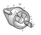
- a drum 10 is journaled on a shaft 12 by means of substantially gas-tight bearings (not shown) at each end, an annular chamber 14 being formed between these two gas-tight bearings.
- the shaft 12 carries a vane 16 which projects into substantially gas-tight engagement with the outer wall 18 of the chamber 14 which is formed by the cylindrical ionner surface of the drum 10.
- the drum 10 has an inwardly projecting vane 20 which extends into gas-tight engagement with the cylindrical surface of the shaft 12.
- a combustion chamber 22 is provided within the shaft 12 and has a duct 24 leading therefrom to one side wall of the vane 16.
- a pyrotechnic charge 26, from which extends a detonation cable 28, is screwed into one end of the chamber 22.
- each end of the drum 10 mounted on each end of the drum 10 for angular movement therewith, is a respective end plate 30, only one of which can be seen in Figure 1.
- a shaft 32, carrying a roller 34, extends between the two end plates 30 at a greater radius from the shaft 12 than the outer surface of the drum 10.
- the drum In use, the drum is initially disposed with its vane 20 closely adjacent to the side of the vane 12 through which the duct 24 emerges.
- the gases produce thereby expand through the duct 24 driving the vane 20 in the direction indicated by the arrow 36, thus causing angular movement of the drum 10 and the roller 34 in a clockwise direction as viewed in Figure 1.
- the various components illustrated in Figure 1 are symmetrical about the plane on which the cross-section is taken.
- the shaft 12 of the unit illustrated in Figure 1 is mounted between two side plates 40 and 42, the front side plate 40 being shown broken away for convenience of illustration.
- the side plates 40 and 42 form part of a frame which is mounted on the inner side of the inner member 44 of the B-post of a motor vehicle. In other words, the assembly is accommodated within the B-post.
- a strap 48 of the safety belt system extends from the retractor 46 between the drum 10 and the roller 34 to a pillar loop 50 which is also mounted on the B-post 44.
- a roller 56 journaled on a shaft 54 which is mounted on the side plates 40 and 42 between the drum 10 and the retractor 46, is positioned so that the strap 48 would only lightly touch it when sufficient of the strap 48 is withdrawn from the retractor 46 to enable the safety belt system to be used.
- Figures 4 and 5 illustrate a second embodiment which differs from the embodiment illustrated in Figures 2 and 3 in two respects.
- the interior of the drum 10 is modified so that the pyrotechnic charge rotates it in the anti-clockwise direction instead of the clockwise direction.
- the side plates 40 and 42 of Figure 2 are replaced by side plates 60 and 62 which extend above the top of the drum 10 to provide support for a shaft 64 on which an additional guide roller 66 is journaled.
- Other components are identical with the corresponding components of Figure 2 and are denoted by the same reference numerals.
- the configuration of the strap 48 prior to detonation of the pyrotechnic charge, as shown in Figure 4, is basically the same as its configuration in the embodiment shown in Figure 2. However, when the charge is detonated, moving the drum 10 and the roller 34 in the anti-clockwise direction, drawing the strap 48 round the drum 10 as illustrated in Figure 5.
- the portion of the strap 48 which is in contact with the surface of the drum is now the portion which extends from the roller 34 to the roller 56 and thence to the retractor 46 (not shown in Figures 4 and 5). Consequently, this portion of the strap 48, which remains stationary from the time when the retractor locks, has to slip over the moving surface of the drum 10, thus somewhat increasing the friction during the initial stage of angular movement.
- the portion of the strap 48 extending from the roller 34 to the pillar loop 50 is now the outside of the double layer on the drum 10, rather than being trapped under the other portion as was the case in Figure 3, thus decreasing the friction during later stages of operation.
- Figures 6 and 7 illustrate a third embodiment which differs from that illustrated in Figures 2 and 3 only in that the side plates 30 on the drum 10 are replaced by side plates 70 carrying two spaced shafts 72 and 74 each of which has a respective roller 76 and 78 journaled thereon.
- the side plates 70 are so oriented relative to the vane 20 ( Figure 1) that, in the pre-detonated condition, the strap 48 passes outside the roller 76 but between the roller 78 and the drum 10 as illustrated in Figure 6.
- the drum 10 and the rollers 74 and 76 move in an anti-clockwise direction.
- Figures 8 and 9 illustrate a fourth embodiment of the invention which differs from the embodiment illustrated in Figures 6 and 7 only in that the side plates 70 are set at a different angle to the vane 20 ( Figure 1) so that, in the pre-detonated state, the strap 48 passes between both rollers 76 and 78 on the one hand and the drum 10 on the other, as illustrated in Figure 8.
- the embodiment illustrated in Figures 8 and 9 may be modified by replacing the rollers 56 and 76 by fixed bars, the former preferably having a high-friction surface.
- the roller 78 is constructed so as to bend under loads of the magnitude encountered during accident conditions so that its central region engages with a stop (not shown) mounted on the side plates 70 between the roller 78 and the fixed bar which replaces the roller 76. This stop serves both to inhibit rotation of the roller 78 and to support some of the load imposed thereon. The result is to increase the friction to which the strap 48 is subject as the drum 10 moves to the position illustrated in Figure 9.
Landscapes
- Engineering & Computer Science (AREA)
- Mechanical Engineering (AREA)
- Automotive Seat Belt Assembly (AREA)
- Devices For Conveying Motion By Means Of Endless Flexible Members (AREA)
Applications Claiming Priority (2)
| Application Number | Priority Date | Filing Date | Title |
|---|---|---|---|
| GB8326889 | 1983-10-07 | ||
| GB838326889A GB8326889D0 (en) | 1983-10-07 | 1983-10-07 | Pyrotechnic tensioner for vehicle safety belt |
Publications (3)
| Publication Number | Publication Date |
|---|---|
| EP0138507A2 true EP0138507A2 (fr) | 1985-04-24 |
| EP0138507A3 EP0138507A3 (en) | 1986-02-12 |
| EP0138507B1 EP0138507B1 (fr) | 1988-07-13 |
Family
ID=10549834
Family Applications (1)
| Application Number | Title | Priority Date | Filing Date |
|---|---|---|---|
| EP84306730A Expired EP0138507B1 (fr) | 1983-10-07 | 1984-10-03 | Tendeur pyrotechnique pour ceinture de Sécurité de véhicule |
Country Status (9)
| Country | Link |
|---|---|
| US (1) | US4597586A (fr) |
| EP (1) | EP0138507B1 (fr) |
| JP (1) | JPS6094850A (fr) |
| AU (1) | AU565021B2 (fr) |
| DE (1) | DE3472649D1 (fr) |
| ES (1) | ES281814Y (fr) |
| GB (1) | GB8326889D0 (fr) |
| SU (1) | SU1304744A3 (fr) |
| ZA (1) | ZA847805B (fr) |
Cited By (4)
| Publication number | Priority date | Publication date | Assignee | Title |
|---|---|---|---|---|
| DE3600650A1 (de) * | 1986-01-11 | 1987-07-16 | Ernst Hans Hellmut | Rotatorischer gurtstraffer fuer sicherheitsgurte |
| DE3606021A1 (de) * | 1986-02-25 | 1987-08-27 | Ernst Hans Hellmut | Rotatorischer gurtstrammer fuer sicherheitsgurte |
| DE3734152A1 (de) * | 1987-10-09 | 1989-04-20 | Ernst Hans Hellmut | Gurtstraffung eines beckengurtendpunktes ueber ein mitfuehrbares zugseil |
| WO1997033777A1 (fr) * | 1996-03-11 | 1997-09-18 | Ab Volvo | Systeme de ceinture de securite |
Families Citing this family (10)
| Publication number | Priority date | Publication date | Assignee | Title |
|---|---|---|---|---|
| US4840325A (en) * | 1986-04-02 | 1989-06-20 | Honda Giken Kogyo Kabushiki Kaisha | Seat belt tightening device |
| US5248110A (en) * | 1991-07-17 | 1993-09-28 | Takata Corporation | Vehicle seat belt retractor |
| US5383623A (en) * | 1992-02-13 | 1995-01-24 | Takata Corporation | Rotary actuator-operated seat belt pretensioner |
| US5489127A (en) | 1993-08-25 | 1996-02-06 | Itt Corporation | Mounting apparatus with reduced resistance bead seal |
| DE29616624U1 (de) * | 1996-09-24 | 1997-01-30 | Trw Occupant Restraint Systems Gmbh, 73551 Alfdorf | Drehantrieb für einen Gurtstraffer |
| DE10052688A1 (de) | 2000-10-24 | 2002-05-23 | Takata Europa Vehicle Safety T | Sicherheitsgurtvorrichtung |
| JP3822617B2 (ja) * | 2004-07-16 | 2006-09-20 | 株式会社コナミデジタルエンタテインメント | ゲーム機の衝撃体感装置およびこの装置を備えたゲーム機 |
| US7350734B2 (en) * | 2005-10-13 | 2008-04-01 | Automotive Systems Laboratory, Inc. | Seat belt pretensioner |
| JP5724862B2 (ja) * | 2011-12-12 | 2015-05-27 | トヨタ自動車株式会社 | シートベルト装置を備えた車両用シート |
| JP7091756B2 (ja) * | 2018-03-22 | 2022-06-28 | マツダ株式会社 | 車両用シートベルト装置 |
Family Cites Families (9)
| Publication number | Priority date | Publication date | Assignee | Title |
|---|---|---|---|---|
| DE2444801C2 (de) * | 1974-09-19 | 1984-11-29 | Volkswagenwerk Ag, 3180 Wolfsburg | Sicherheitsgurteinrichtung |
| DE2510514C3 (de) * | 1975-03-11 | 1980-01-10 | Bayern-Chemie Gesellschaft Fuer Flugchemische Antriebe Mbh, 8261 Aschau | Aufwickelvorrichtung für Sicherheitsgurte mit pyrotechnisch angetriebener Schnelldreheinrichtung |
| US4385775A (en) * | 1978-03-21 | 1983-05-31 | Nippon Soken, Inc. | Seat belt tensioning device for vehicle |
| FR2430241A1 (fr) * | 1978-07-05 | 1980-02-01 | Renault | Dispositif tendeur de sangle pour ceintures de securite |
| DE3044951C2 (de) * | 1980-11-28 | 1986-03-27 | Repa Feinstanzwerk Gmbh, 7071 Alfdorf | Rückstrammer für einen Sicherheitsgurt |
| JPS5825156U (ja) * | 1981-08-12 | 1983-02-17 | トヨタ自動車株式会社 | シ−トベルト引締め装置 |
| DE3307093A1 (de) * | 1982-03-03 | 1983-09-08 | Hans-Hellmut Dipl.-Ing. 2061 Sülfeld Ernst | B-/c-saeule eines kfz mit integrierten sicherheitsgurtelementen |
| DE3215928C2 (de) * | 1982-04-29 | 1985-11-21 | Bayern-Chemie Gesellschaft für flugchemische Antriebe mbH, 8261 Aschau | Aufwickelvorrichtung für Sicherheitsgurte |
| DE3215926C2 (de) * | 1982-04-29 | 1985-09-19 | Bayern-Chemie Gesellschaft für flugchemische Antriebe mbH, 8261 Aschau | Aufwickelvorrichtung mit Rückstrammer für Sicherheitsgurte in Fahrzeugen |
-
1983
- 1983-10-07 GB GB838326889A patent/GB8326889D0/en active Pending
-
1984
- 1984-10-03 DE DE8484306730T patent/DE3472649D1/de not_active Expired
- 1984-10-03 EP EP84306730A patent/EP0138507B1/fr not_active Expired
- 1984-10-04 AU AU33830/84A patent/AU565021B2/en not_active Ceased
- 1984-10-04 ZA ZA847805A patent/ZA847805B/xx unknown
- 1984-10-05 ES ES1984281814U patent/ES281814Y/es not_active Expired
- 1984-10-05 SU SU843797703A patent/SU1304744A3/ru active
- 1984-10-08 JP JP59211184A patent/JPS6094850A/ja active Pending
- 1984-10-09 US US06/658,538 patent/US4597586A/en not_active Expired - Fee Related
Cited By (6)
| Publication number | Priority date | Publication date | Assignee | Title |
|---|---|---|---|---|
| DE3600650A1 (de) * | 1986-01-11 | 1987-07-16 | Ernst Hans Hellmut | Rotatorischer gurtstraffer fuer sicherheitsgurte |
| DE3606021A1 (de) * | 1986-02-25 | 1987-08-27 | Ernst Hans Hellmut | Rotatorischer gurtstrammer fuer sicherheitsgurte |
| DE3734152A1 (de) * | 1987-10-09 | 1989-04-20 | Ernst Hans Hellmut | Gurtstraffung eines beckengurtendpunktes ueber ein mitfuehrbares zugseil |
| DE3734152C2 (de) * | 1987-10-09 | 1998-04-09 | Gen Engineering Bv | Gurtstraffung eines Beckengurtendpunktes über ein mitgeführtes Zugseil |
| WO1997033777A1 (fr) * | 1996-03-11 | 1997-09-18 | Ab Volvo | Systeme de ceinture de securite |
| US6264280B1 (en) | 1996-03-11 | 2001-07-24 | Ab Volvo | Safety-belt arrangement |
Also Published As
| Publication number | Publication date |
|---|---|
| EP0138507A3 (en) | 1986-02-12 |
| ES281814U (es) | 1986-04-16 |
| DE3472649D1 (en) | 1988-08-18 |
| AU565021B2 (en) | 1987-09-03 |
| ZA847805B (en) | 1985-05-29 |
| SU1304744A3 (ru) | 1987-04-15 |
| ES281814Y (es) | 1986-12-01 |
| EP0138507B1 (fr) | 1988-07-13 |
| US4597586A (en) | 1986-07-01 |
| GB8326889D0 (en) | 1983-11-09 |
| JPS6094850A (ja) | 1985-05-28 |
| AU3383084A (en) | 1985-04-18 |
Similar Documents
| Publication | Publication Date | Title |
|---|---|---|
| US4597586A (en) | Pyrotechnic tensioner for vehicle safety belt | |
| US5785269A (en) | Dual level retractor for oblique or offset impacts | |
| US4163530A (en) | Device for preventing the drawing-out of a seat belt webbing at the lock of a retractor | |
| US4398680A (en) | Webbing locking device | |
| EP0600689A1 (fr) | Rétracteur de ceinture de sécurité à prétensionneur | |
| US4360171A (en) | Seat belt retracting and locking mechanism | |
| AU2003263382A1 (en) | A web spool tightener | |
| US4674700A (en) | Retractor reel for a vehicle safety belt | |
| EP0237503B1 (fr) | Dispositif de tensionnement pour ceintures de sécurité pour véhicules automobiles | |
| US4141518A (en) | Safety-belt retractor | |
| US20030001041A1 (en) | Pretensioner structure for a safety belt of an automobile | |
| US4222588A (en) | Seatbelt system | |
| US4371126A (en) | Webbing lock device | |
| US6240848B1 (en) | Device for firing a pyrotechnic propellent composition | |
| US3306552A (en) | Seat belt retractor | |
| KR100471028B1 (ko) | 자동차 시트벨트의 리트랙터 장치 | |
| US6676057B2 (en) | Drive for a belt tensioner | |
| SE8006082L (sv) | Beltesupprullare for fordons-sekerhetsbelten | |
| KR20130055106A (ko) | 차량용 시트벨트의 리트렉터 통합 프리텐셔너 장치 | |
| KR20020027901A (ko) | 자동차용 시트 벨트 | |
| EP4582316A1 (fr) | Dispositif de capteur de véhicule et rétracteur de ceinture de sécurité auquel il est appliqué | |
| KR100427275B1 (ko) | 자동차용 프리텐셔너 구조 | |
| KR0124011Y1 (ko) | 차량용 프리텐션어의 로터식 감김구조 | |
| KR200163126Y1 (ko) | 시트벨트용 리트랙터 | |
| US4248456A (en) | Seatbelt system |
Legal Events
| Date | Code | Title | Description |
|---|---|---|---|
| PUAI | Public reference made under article 153(3) epc to a published international application that has entered the european phase |
Free format text: ORIGINAL CODE: 0009012 |
|
| AK | Designated contracting states |
Designated state(s): DE FR GB IT SE |
|
| PUAL | Search report despatched |
Free format text: ORIGINAL CODE: 0009013 |
|
| AK | Designated contracting states |
Designated state(s): DE FR GB IT SE |
|
| 17P | Request for examination filed |
Effective date: 19860211 |
|
| 17Q | First examination report despatched |
Effective date: 19870317 |
|
| GRAA | (expected) grant |
Free format text: ORIGINAL CODE: 0009210 |
|
| AK | Designated contracting states |
Kind code of ref document: B1 Designated state(s): DE FR GB IT SE |
|
| REF | Corresponds to: |
Ref document number: 3472649 Country of ref document: DE Date of ref document: 19880818 |
|
| ET | Fr: translation filed | ||
| ITF | It: translation for a ep patent filed | ||
| PLBE | No opposition filed within time limit |
Free format text: ORIGINAL CODE: 0009261 |
|
| STAA | Information on the status of an ep patent application or granted ep patent |
Free format text: STATUS: NO OPPOSITION FILED WITHIN TIME LIMIT |
|
| 26N | No opposition filed | ||
| PGFP | Annual fee paid to national office [announced via postgrant information from national office to epo] |
Ref country code: SE Payment date: 19891010 Year of fee payment: 6 |
|
| PG25 | Lapsed in a contracting state [announced via postgrant information from national office to epo] |
Ref country code: SE Effective date: 19901004 |
|
| PGFP | Annual fee paid to national office [announced via postgrant information from national office to epo] |
Ref country code: GB Payment date: 19910920 Year of fee payment: 8 |
|
| ITTA | It: last paid annual fee | ||
| PG25 | Lapsed in a contracting state [announced via postgrant information from national office to epo] |
Ref country code: GB Effective date: 19921003 |
|
| GBPC | Gb: european patent ceased through non-payment of renewal fee |
Effective date: 19921003 |
|
| PGFP | Annual fee paid to national office [announced via postgrant information from national office to epo] |
Ref country code: FR Payment date: 19931011 Year of fee payment: 10 |
|
| EUG | Se: european patent has lapsed |
Ref document number: 84306730.7 Effective date: 19910603 |
|
| PG25 | Lapsed in a contracting state [announced via postgrant information from national office to epo] |
Ref country code: FR Effective date: 19950630 |
|
| REG | Reference to a national code |
Ref country code: FR Ref legal event code: ST |
|
| PGFP | Annual fee paid to national office [announced via postgrant information from national office to epo] |
Ref country code: DE Payment date: 19961011 Year of fee payment: 13 |
|
| PG25 | Lapsed in a contracting state [announced via postgrant information from national office to epo] |
Ref country code: DE Free format text: LAPSE BECAUSE OF NON-PAYMENT OF DUE FEES Effective date: 19980701 |